

диафрагмированные волноводные фильтры / b937da4c-7527-47a5-a000-d147c076bd27
.pdfReceived March 15, 2019, accepted April 2, 2019, date of publication April 9, 2019, date of current version April 25, 2019.
Digital Object Identifier 10.1109/ACCESS.2019.2909771
Integration Design of Millimeter-Wave Filtering
Patch Antenna Array With SIW Four-Way
Anti-Phase Filtering Power Divider
HUAYAN JIN 1, (Member, IEEE), GUO QING LUO
 1, (Member, IEEE), WENLEI WANG1,
WENQUAN CHE 2, (Senior Member, IEEE), AND KUO-SHENG CHIN
 3, (Senior Member, IEEE)
1Key Laboratory of RF Circuits and System, Institute of Antennas and Microwave Technology, Ministry of Education, Hangzhou Dianzi University, Hangzhou 310018, China
2School of Electronic and Information Engineering, South China University of Technology, Guangzhou 510641, China 3Department of Electronic Engineering, Chang Gung University, Taoyuan 333, Taiwan
Corresponding author: Guo Qing Luo (luoguoqing@hdu.edu.cn)
This work was supported in part by the Zhejiang Provincial Natural Science Foundation of China under Grant LQ18F010003, and in part by the National Natural Science Foundation of China under Contract 61722107.
 ABSTRACT In this paper, the integration design of a millimeter-wave ltering patch antenna array fed by a substrate integrated waveguide (SIW) four-way anti-phase ltering power divider is proposed. The multilayer four-way anti-phase ltering power divider handily implemented using the intrinsic eld distribution of TE20-mode in SIW is proposed for miniaturization. The signal of the lower substrate integrated waveguide cavity (SIWC) bandpass lter is directly coupled to the upper TE20-mode SIW through a coupling slot. The intrinsic eld distribution of TE20-mode SIW is used to generate anti-phase signals. This ltering power divider can be utilized as the feeding structure of a millimeter-wave ltering antenna array. To verify the design concept, a 28-GHz SIW-fed 1 4 ltering patch antenna array with three-layer substrates is designed and fabricated. The measured results show a fractional bandwidth of 5.03% ranging from 27.15 to 28.55 GHz, a peak gain of 11.1 dBi, cross-polarization levels lower than -20 dB, symmetric radiation patterns in both E-plane and H-plane, and high selectivity.
 INDEX TERMS Dual-slot-fed patch, ltering antenna array, millimeter-wave antenna array, substrate integrated waveguide (SIW), TE 20-mode.
I. INTRODUCTION
The rapid development of modern wireless and mobile communication industries proposes stringent requirements on the RF front-end systems with compact size, high-ef ciency and good stability. Multifunctional components such as balun bandpass lter [1], ltering power dividers [2], and ltering antennas [3], [4], have received increasing attentions due to their advantages of compact size and low insertion loss. Traditionally, the bandpass lter and antenna, which are two key components in the RF-front ends, are designed individually and then combined by matching networks. This design is not appropriate to circuit miniaturization and will add extra insertion losses. Filtering antennas, which combine the separated antenna and lter into one, can perform ltering response in both the re ection coef cient and realized gain, for size and loss reduction.
The associate editor coordinating the review of this manuscript and approving it for publication was Xiaojie Su.
There have been extensive investigations on ltering antennas [3] [7]. In [3], one ltering antenna, also called as `` l- tenna'', is constructed by a horn antenna and an X-band bandpass frequency selective surface. A high-gain ltering patch antenna operating at the band of LTE (Long term evolution) without extra ltering circuits was presented in [4]. In [5], one X-band ltering aperture antenna array was designed using rectangular waveguide structures. Three-dimensional ltering slot antenna realized at Ka-band using substrate-integrated waveguide (SIW) technique was proposed in [6]. In [7], an SIW-based circularly-polarizedltering patch antenna array was proposed around X-band. Although the above ltering antennas achieve good ltering response, few of them operate at millimeter-wave (MMW) band.
Power dividers, especially multi-way power dividers, are indispensable parts to the design of antenna arrays. Various multi-way power dividers were presented in [8] [10].
2169-3536 2019 IEEE. Translations and content mining are permitted for academic research only.
49804 Personal use is also permitted, but republication/redistribution requires IEEE permission. VOLUME 7, 2019 See http://www.ieee.org/publications_standards/publications/rights/index.html for more information.

H. Jin et al.: Integration Design of MMW Filtering Patch Antenna Array With SIW Four-Way Anti-Phase Filtering Power Divider
Bandpass lter is another important device in RF systems to reject unwanted signals. These two devices are generally cascaded in the feed networks of antenna arrays. This is the simplest method to construct a ltering power divider, but often at the cost of increasing the size and degrading the in-band performance of antennas. To overcome such shortcomings, the designs of ltering power dividers with low insertion loss, compact size, and low cost were developed [11] [13]. However, most of the previous works are based on microstrip structures, which may suffer from high insertion loss in MMW systems. SIW structures featuring low insertion losses and high power handling capacities have been widely used in various MMW circuits [14] [16]. However, SIW power dividers with multi-ways have the disadvantages of large size due to an increased number of ports, and may suffer with poor impedance matching at all ports [9]. The development of MMW SIW multi-way ltering power divider and its application are rarely reported. Because of the in uence of small size and serious parasitic effects on MMW antenna designs, how to combine the ltering, power-dividing, and radiating structures into antennas for achieving multifunction is challenging. At present, the frequency bands of the publishedltering antenna designs were mostly below 6 GHz. Very few MMW-band antenna arrays with the differential feed network were developed for ltering response, high gain, low cross polarization, and symmetric radiation patterns, which are the focus of this work.
FIGURE 1. 3-D view of the proposed millimeter-wave filtering patch antenna array.
In this paper, the integration design of a MMW ltering patch antenna array is proposed, as shown in Fig. 1. It consists of a novel compact SIW four-way anti-phase ltering power divider and two series-fed 1 2 patch antenna sub-arrays. The proposed SIW ltering power divider is handily implemented using the opposite current directions along a coupling slot and the intrinsic eld distribution of TE20 mode SIW to achieve compact size. It also achieves excellent ltering characteristic, impedance matching at all ports, and amplitude balance at the output ports by integrating a SIWC (SIW cavity) bandpass lter and TE20-mode SIW feed lines. This power divider can directly connect the sub-arrays through TE20-mode SIW without any impedance matching networks.
VOLUME 7, 2019
The implemented ltering antenna array shows superior l- tering response, at in-band gain curve, and high out-of-band suppression.
II. FOUR-WAY ANTI-PHASE SIW FILTERING POWER DIVIDER
As it is well known, the differential circuits have the ability to reject common-mode noise compared to single-ended circuits. Furthermore, differential-fed antennas can also reduce cross polarization and improve radiation pattern symmetry [17]. For the design of differential-fed antenna arrays, the anti-phase feed network is required.
In conventional SIW-based structures, an anti-phase l- tering power divider is composed by cascade connection of power dividers, bandpass lters, and phase shifters, which will suffer from high loss, large size, and complexity. A compact multilayer four-way anti-phase power divider handily implemented a coupling slot and the intrinsic eld distribution of TE20 mode SIW is proposed in this work.
A. ANALYSIS AND DESIGN
Fig. 2 shows the con guration of the proposed SIW fourway anti-phase ltering power divider. It consists of a coupling slot, a third-order TE110-mode SIWC bandpass lter, a TE20-mode SIW, and microstrip feed lines. The coupling slot, SIWC bandpass lter, and TE20-mode SIW are implemented together to obtain ltering response and four-way anti-phase outputs. Note that the four output ports of Port
FIGURE 2. Configuration of the proposed SIW four-way anti-phase filtering power divider: (a) 3-D view and (b) Top view.
49805

H. Jin et al.: Integration Design of MMW Filtering Patch Antenna Array With SIW Four-Way Anti-Phase Filtering Power Divider
2 Port 5 are used only for the performance evaluation, which can be removed in the nal array design. The jS21j 3-dB bandwidth ranging from 27.22 to 29.15 GHz is designed in this work for 5G wireless applications, which requires a fractional bandwidth of 6.8%. When selecting a third-order maximally at response and fractional bandwidth of 6.8%, the corresponding coupling coef cients and external quality factor for the SIWC bandpass lter are M12 D M23 D 0.048 and Qe D 14.71, respectively, where Mij is the coupling coef cient between the ith and jth cavities. Fig. 3 shows the design curve of coupling coef cient of the SIWC bandpasslter, which can be used to determine the window length L according to the required Mij.
respectively, c is the light velocity of free space, a and b are the width and length of the SIW cavity, respectively, and dv and pv are the diameter of metalized via holes and center- to-center pitch between two adjacent via holes, respectively. The nal dimensions of the SIWC are determined by the optimized S-parameter responses, which give a D 6.15 mm and b D 4.4 mm.
FIGURE 3. Coupling coefficient of the SIWC bandpass filter.
The power divider is designed with two-layer substrates and optimized by the full-wave EM simulator Ansoft HFSS. The Rogers 4003C ("r D 3.55 and tan D 0.0029 at 10 GHz) with a thickness of 0.5 mm was used for the upper TE20-mode SIW, while the Rogers RT/Duroid 5880 ("r D 2.22 and tan D 0.0009 at 10 GHz) with a thickness of 0.254 mm was used for the lower SIWC bandpass lter. A common ground plane with a coupling slot was inserted between the two substrates. The input signal from Port 1 propagates along the third-order SIWC bandpass lter, and then is directly coupled to the upper TE20-mode SIW from the third resonant cavity without any additional structures and equally divided into two TE20-mode signals. The coupling slot located along the longitudinal center of the TE20-mode SIW line is in charge to generate the TE20-mode eld distribution. The intrinsic eld distribution of TE20-mode in SIW can be used to construct four-way anti-phase signals.
The SIWC bandpass lter is constructed by three SIW cavities operating at the TE110 dominant mode, whose resonant frequency can be determined by [18]:
f110 D |
2 pc r "r s |
Weff |
|
C Leff |
|
(1) |
|||||||
|
|
|
|
|
|
|
|
|
2 |
|
2 |
|
|
|
|
|
|
|
|
|
|
|
|
|
|
|
|
|
|
|
d2 |
|
|
|
|
|
d |
2 |
|
|
|
Weff D a |
|
v |
; Leff |
D b |
v |
|
(2) |
||||||
0:95pv |
0:95pv |
||||||||||||
where f110 denotes the eigenmode frequency, "r and r are the relative permittivity and permeability of the substrate,
49806
FIGURE 4. (a) The electric field amplitude distribution and (b) the current distribution of TE20-mode SIW and the microstrip lines.
The electric eld and current distributions of the TE20-mode SIW and the microstrip lines are shown in Figs. 4(a) and 4(b), respectively. As indicated in Fig. 4, the amplitude distribution of the electric eld is symmetric with respect to the AA' line, whereas the current distribution shows odd symmetric with respect to the AA' line. Therefore, the TE20 mode on each side of the SIW can support differential signals with same amplitude and opposite phase.
B. SIMULATED RESULTS
A millimeter-wave SIW four-way anti-phase ltering power divider is designed according to the aforementioned method for operating at 28 GHz. The detailed dimensions are listed in Table 1. Fig. 5(a) shows the simulated S-parameter magnitudes of the ltering power divider. This divider exhibits a fractional bandwidth of 4.8% at 28.17 GHz ranging from 27.49 to 28.85 GHz with the re ection coef cient less than -15 dB. The same S-parameter magnitudes of the four output ports with maximally at responses are observed due to the symmetric structure. Fig. 5(b) shows the phase responses of the output ports. As indicated, the Port 2 and Port 4 (Port 3 and Port 5) are in-phase and the Port 2 and Port 3 (Port 4 and Port 5) are 180 out of phase. The amplitude and phase imbalances of the output ports are less than 0.2 dB and 180 1 , respectively.
VOLUME 7, 2019

H. Jin et al.: Integration Design of MMW Filtering Patch Antenna Array With SIW Four-Way Anti-Phase Filtering Power Divider
A. SERIES-FED 1 2 SUB-ARRAY
Figs. 6(a) and 6(b) show the con guration of the proposed 1 2 TE20-mode SIW series-fed sub-array, which is designed with two-layer Rogers 4003C ("r D 3.55 and tan D 0.0029 at 10 GHz) substrates with a thickness of 0.5 mm. Fig. 6(c) illustrates the current distribution on the dual-slot-fed patch elements with TM10-mode excitation
FIGURE 5. Simulated S parameters of the proposed TE20-mode SIW four-way anti-phase filtering power divider: (a) Magnitudes and (b) phase differences between the output ports.
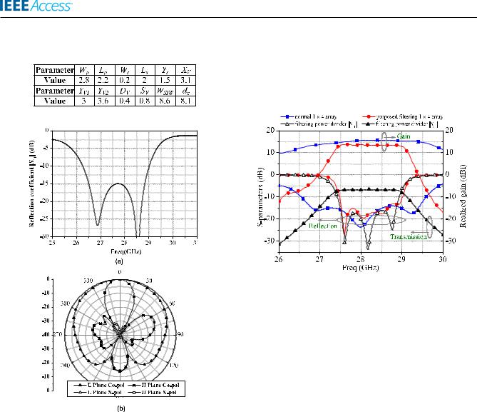
TABLE 1. Dimensions of the filtering power divider (in mm).
III. INTEGRATION DESIGN OF THE MILLIMETER-WAVE FILTERING PATCH ANTENNA ARRAY
A millimeter-wave 1 4 TE20-mode SIW dual-slot-fed patch antenna array integrated with the proposed ltering power divider is designed to achieve high selectivity. Two series-fed 1 2 sub-arrays are used to construct the 1 4 patch antenna array. The ltering power divider is implemented in the center underneath the two sub-arrays, as shown in Fig. 1. The TE20-mode SIW dual-slot-fed patch structure [19], which features wider bandwidth and higher gain than the conventional TE10 single-slot-fed patch antennas, is adopted in this work. The detailed designs of the 1 2 sub-arrays and the 1 4 ltering patch antenna array are explained as follows.
VOLUME 7, 2019
FIGURE 6. Configuration of the TE20-mode SIW series-fed 1 2 sub-array with dual-slot-fed patch elements: (a) 3-D view, (b) top view, and
(c) current distribution on the dual-slot-fed patch elements.
49807
H. Jin et al.: Integration Design of MMW Filtering Patch Antenna Array With SIW Four-Way Anti-Phase Filtering Power Divider
TABLE 2. Dimensions of The Filtering Powered divider (in mm).
FIGURE 7. Simulated results of the proposed TE20-mode SIW series-fed 1 2 sub-array: (a) jS11j and (b) radiation patterns at 28 GHz.
at 28 GHz. The detailed dimensions are listed in Table 2. Fig. 7(a) shows the simulated re ection coef cient jS11j of the 1 2 sub-array, which has an impedance bandwidth of 9.95% (26.25 29 GHz) with the re ection coef cient less than 10 dB. The simulated gain at 28 GHz is 12.3 dBi. Fig. 7(b) shows the radiation patterns of the 1 2 sub-array at 28 GHz. The E-plane co-polarization radiation pattern is symmetric due to the symmetric dual-slot feeding structure, whereas the peak gain of the H-plane co-polarization radiation pattern is slightly deviated from 0 caused by the series-fed structure. The cross-polarization levels are lower than -30 dB in both E-plane and H-plane.
B. 1 4 FILTERING PATCH ANTENNA ARRAY
The integrated 1 4 parallel-series-fed ltering patch antenna array is shown in Fig. 1. The overall structure occupies three substrates. The SIW four-way anti-phase ltering power divider provides two-way TE20-mode signals withltering response, which can be used to excite the series-fed
49808
1 2 sub-arrays. In order to improve the deterioration of the H-plane radiation pattern caused by the series-fed structure, two 1 2 sub-arrays are mirror-arranged by using a parallel feed with the ltering power divider in the middle underneath them.
FIGURE 8. Simulated jS11j and gain curves of the proposed filtering 1 4 antenna array and a reference 1 4 antenna array without the filtering power divider, and the jS11j and jS21j responses of the proposed filtering power divider.
Fig. 8 shows the simulated jS11j responses and gain curves of the proposed ltering 1 4 antenna array and a reference 1 4 antenna array without the ltering power divider, and the jS11j and jS21j responses of the proposed ltering power divider. As indicated, the gain curve of the proposed ltering antenna array has similar roll-off characteristic to the jS21j response of the proposed ltering power divider, in which the difference of in-band levels between the two curves corresponds to the directivity of the antenna array. A -10-dB impedance bandwidth of 5.4% ranging from 27.48 to 29 GHz is achieved, which is slightly wider than that of the ltering power divider. The peak gain of 13.5 dBi is obtained at 28 GHz. The at gain curve is observed and the gain variation is less than 0.4 dB in the passband. Fig. 9 shows the simulated radiation patterns at 28 GHz. Due to the symmetric parallel-series feed structure, the 1 4 array can achieve symmetric radiation patterns and low cross-polarization levels less than -40 dB in both E-plane and H-plane.
IV. EXPERIMENTAL RESULTS
To verify the design, a prototype of ltering 1 4 array was fabricated and measured, as illustrated in Fig. 10. For the cost issue, the proposed three-layer circuits were fabricated individually and then assembled together by screws. A steel support is used to screw the separated circuit boards and the edge-fed SMA connector. The total size is 33 27 mm2.
A. IMPEDANCE BANDWIDTH AND RADIATION GAIN
Fig. 11 shows the simulated and measured broadside gain curves and jS11j responses of the proposed ltering 1 4 patch antenna array. The superior re ection coef cient
VOLUME 7, 2019

H. Jin et al.: Integration Design of MMW Filtering Patch Antenna Array With SIW Four-Way Anti-Phase Filtering Power Divider
FIGURE 9. Simulated radiation patterns of the proposed 1 4 filtering antenna array at 28 GHz.
FIGURE 10. Photograph of the fabricated PCB-based 1 4 filtering antenna array: (a) Expanded view and (b) assembled view.
and high selectivity are achieved around 28 GHz. The measured impedance bandwidth is 5.03% (27.15 28.55 GHz). The measured gain is above 10 dBi from 27.2 to 28 GHz with a peak gain of 11.1 dBi at 27.6 GHz. The in-band gain curve isat and degrades rapidly in out-of-band with high selectivity. The measured center frequency and bandwidth are slightly decreased from the simulated results due to the possible small air gaps existing between two substrates and the uncertain permittivity of the substrates in millimeter-wave band, which can be improved by adopting accurate multi-layer PCB or LTCC fabrication process with a certain permittivity of substrates.
B. RADIATION PATTERNS
Fig. 12 shows the simulated and measured radiation patterns of the proposed ltering 1 4 array at 28 GHz. Owing to
FIGURE 11. Comparison of the measured and simulated gain curves and jS11j responses of the proposed 1 4 filtering patch antenna array.
FIGURE 12. Simulated and measured radiation patterns at 28 GHz: (a) E-plane and (b) H-plane.
the symmetric ltering power divider, the radiation patterns of the array are symmetric in both E-plane and H-plane. The measured cross-polarization levels are below 20 dB in both E-plane and H-plane. The deviation in cross-polarization and side-lobe levels from the simulated results is mainly due to the unbalanced steel support and SMA connector and the fabrication tolerance.
VOLUME 7, 2019 |
49809 |

H. Jin et al.: Integration Design of MMW Filtering Patch Antenna Array With SIW Four-Way Anti-Phase Filtering Power Divider
TABLE 3. Comparison with previously reported filtering antenna arrays.
FIGURE 13. Simulated E-plane co-polarization patterns for various hw .
As shown in Fig. 10(b), the steel support includes horizontal and vertical parts. The two vertical parts behave as two re ected walls lie on the yz-plane, which in uence the E-plane radiation patterns of the complete antenna array. The height of the vertical parts above the ground is marked as hw. Fig. 13 shows the impact of hw on the simulated E-plane co-polarization radiation patterns. As indicated, the side-lobe level increases as hw increases. When hw D 0 mm, the peak of radiation patterns is slightly shifted from 0 boresight and results in asymmetric radiation pattern. It is mainly caused by the SMA connector even the vertical parts of the steel support are absent. However, all these problems can be further improved by adopting multi-layer PCB fabrication process and low-pro le connectors.
Table 3 lists the performance comparison among our work and other published ltering antennas. As indicated, the proposed millimeter-wave ltering antenna array features high gain, differential feed network, low cross polarization, and symmetric radiation patterns in both E-plane and H-plane.
V. CONCLUSION
In this paper, a novel SIW four-way anti-phase ltering power divider is rstly presented, which features symmetric structure, low amplitude and phase imbalances, and high selectivity. Two series-fed 1 2 sub-arrays are used to construct the parallel-series-fed 1 4 patch antenna array to achieve symmetric radiation patterns in both E-plane and H-plane.
49810
The proposed 1 4 antenna array can achieve high selectivity, symmetric radiation patterns, and low cross-polarization level in millimeter-wave band.
REFERENCES
[1]D. Chen, L. Zhu, H. Bu, and C. Cheng, ``A wideband balun lter on a triple-mode slotline resonator with controllable bandwidth,'' IEEE Microw. Wireless Compon. Lett., vol. 27, no. 6, pp. 569 571, Jun. 2017.
[2]H. Zhu, A. M. Abbosh, and L. Guo, ``Wideband four-way ltering power divider with sharp selectivity and wide stopband using looped coupledline structures,'' IEEE Microw. Wireless Compon. Lett., vol. 26, no. 6,
pp.413 415, Jun. 2016.
[3]G. Q. Luo et al., ``Filtenna consisting of horn antenna and substrate integrated waveguide cavity FSS,'' IEEE Trans. Antennas Propag., vol. 55, no. 1, pp. 92 98, Jan. 2007.
[4]X. Y. Zhang, W. Duan, and Y.-M. Pan, ``High-gain ltering patch antenna without extra circuit,'' IEEE Trans. Antennas Propag., vol. 63, no. 12,
pp.5883 5888, Dec. 2015.
[5]F.-C. Chen, J.-F. Chen, Q.-X. Chu, and M. J. Lancaster, ``X-band waveguide ltering antenna array with nonuniform feed structure,'' IEEE Trans. Microw. Theory Techn., vol. 65, no. 12, pp. 4843 4850, Dec. 2017.
[6]H. Chu, C. Jin, J.-X. Chen, and Y.-X. Guo, ``A 3-D millimeterwave ltering antenna with high selectivity and low cross-polarization,''
IEEE Trans. Antennas Propag., vol. 63, no. 5, pp. 2375 2380, May 2015.
[7]T. Li and X. Gong, ``Vertical integration of high-Q lter with circularly polarized patch antenna with enhanced impedance-axial ratio bandwidth,'' IEEE Trans. Antennas Propag., vol. 66, no. 6, pp. 3119 3128, Jun. 2018.
[8]K. Song, Y. Mo, Q. Xue, and Y. Fan, ``Wideband four-way out-of-phase slotline power dividers,'' IEEE Trans. Ind. Electron., vol. 61, no. 7,
pp.3598 3606, Jul. 2014.
[9]D. S. Eom, J. Byun, and H. Y. Lee, ``Multilayer substrate integrated waveguide four-way out-of-phase power divider,'' IEEE Trans. Microw. Theory Techn., vol. 57, no. 12, pp. 3469 3476, Dec. 2009.
[10]J. Dong, Y. Liu, Z. Yang, H. Peng, and T. Yang, ``Broadband millimeterwave power combiner using compact SIW to waveguide transition,''
IEEE Microw. Wireless Compon. Lett., vol. 25, no. 9, pp. 567 569, Sep. 2015.
[11]C. Zhu, J. Xu, and W. Wu, ``Microstrip four-way recon gurable single/dual/wideband ltering power divider with tunable frequency, bandwidth and PDR,'' IEEE Trans. Ind. Electron., vol. 65, no. 11,
pp.8840 8850, Nov. 2018.
[12]X. Zhao, K. Song, Y. Zhu, and Y. Fan, ``Wideband four-way ltering power divider with isolation performance using three parallel-coupled lines,'' IEEE Microw. Wireless Compon. Lett., vol. 27, no. 9, pp. 800 802, Sep. 2017.
[13]C.-K. Lin and S.-J. Chung, ``A ltering microstrip antenna array,'' IEEE Trans. Microw. Theory Techn., vol. 59, no. 11, pp. 2856 2863, Nov. 2011.
[14]Z.-C. Hao, Q. Yuan, B.-W. Li, and G. Q. Luo, ``Wideband W- band substrate-integrated waveguide magnetoelectric (ME) dipole array antenna,'' IEEE Trans. Antennas Propag., vol. 66, no. 6, pp. 3195 3200, Jun. 2018.
[15]K. K. Fan, Z.-C. Hao, Q. Yuan, J. Hu, G. Q. Luo, and W. Hong, ``Wideband horizontally polarized omnidirectional antenna with a conical beam for millimeter-wave applications,'' IEEE Trans. Antennas Propag., vol. 66, no. 9, pp. 4437 4448, Sep. 2018.
VOLUME 7, 2019

H. Jin et al.: Integration Design of MMW Filtering Patch Antenna Array With SIW Four-Way Anti-Phase Filtering Power Divider
[16]H. Chu, J.-X. Chen, S. Luo, and Y.-X. Guo, ``A millimeter-wave ltering monopulse antenna array based on substrate integrated waveguide technology,'' IEEE Trans. Antennas Propag., vol. 64, no. 1, pp. 316 321, Jan. 2016.
[17]H. Y. Jin, K.-S. Chin, W. Q. Che, C.-C. Chang, H.-J. Li, and Q. Xue, ``A broadband patch antenna array with planar differential L-shaped feeding structures,'' IEEE Antennas Wireless Propag. Lett., vol. 14,
pp.127 130, 2015.
[18]Y. Cassivi and K. Wu, ``Low cost microwave oscillator using substrate integrated waveguide cavity,'' IEEE Microw. Wireless Compon. Lett., vol. 13, no. 2, pp. 48 50, Feb. 2003.
[19]H. Jin, W. Che, K. S. Chin, W. Yang, and Q. Xue, ``Millimeter-wave TE20-mode SIW dual-slot-fed patch antenna array with a compact differential feeding network,'' IEEE Trans. Antennas Propag., vol. 66, no. 1,
pp.456 461, Jan. 2018.
[20]Y. Yusuf. H. Cheng, and X. Gong, ``Co-designed substrate-integrated waveguide lters with patch antennas,'' IET Microw., Antennas Propag., vol. 7, no. 7, pp. 493 501, May 2013.
[21]L. Li and G. Liu, ``A differential microstrip antenna with ltering response,'' IEEE Antennas Wireless Propag. Lett., vol. 15, pp. 1983 1986, 2016.
HUAYAN JIN was born in Hangzhou, Zhejiang, China, in 1989. She received the B.S. degree in electronic engineering and the Ph.D. degree in electromagnetic eld and microwave technology from the Nanjing University of Science and Technology (NUST), Nanjing, China, in 2011 and 2017, respectively.
From 2012 to 2014, she was an Exchange Student with Chang Gung University, Taoyuan, Taiwan. She is currently a Lecturer with the School
of Electronics and Information, Hangzhou Dianzi University, Hangzhou, China. Her main research interests include millimeter-wave antennas, differential-fed antennas, and ltering antennas. She serves as a Reviewer for the IEEE ACCESS, IET Microwaves, Antennas and Propagation, IET Electronics Letters, and the International Journal of Electronics.
GUO QING LUO (M'08) received the B.S. degree from the China University of Geosciences, Wuhan, China, in 2000, the M.S. degree from Northwest Polytechnical University, Xi'an, China, in 2003, and the Ph.D. degree from Southeast University, Nanjing, China, in 2007.
Since 2007, he has been a Lecturer with the Faculty of School of Electronics and Information, Hangzhou Dianzi University, Hangzhou, China, where he was promoted as a Professor, in 2011.
From 2013 to 2014, he was with the Department of Electrical, Electronic and Computer Engineering, Heriot-Watt University, Edinburgh, U.K., as a Research Associate, where he was involved in developing low pro le antennas for UAV applications. He has authored or coauthored more than 90 technical papers in refereed journals and conferences. He holds 16 patents. His current research interests include RF, microwave and mm-wave passive devices, antennas, and frequency selective surfaces.
Dr. Luo was a recipient of the CST University Publication Award, in 2007, the National Excellent Doctoral Dissertation of China, in 2009, and the National Natural Science Award (Second Class) of China, in 2016. He has served as the Organizing Committee Chair for the 2011 China-Japan Joint Microwave Conference (CJMW 2011), the TPC Chair for the 2017 National Conference on Microwave and Millimeter Waves (NCMMW 2017), and a TPC Chair for the 2018 U.K.-Europe-China Workshop on Millimeter Waves and Terahertz Technologies (UCMMT 2018). He is the Chair of the Hangzhou Chapter, IEEE Microwave Theory and Techniques Society. He also serves a Reviewer for many technical journals, including the IEEE
TRANSACTIONS ANTENNAS PROPAGATION, the IEEE TRANSACTIONS ON MICROWAVE
THEORY AND TECHNIQUES, the IEEE ANTENNAS WIRELESS PROPAGATION LETTERS, the IEEE MICROWAVE WIRELESS COMPONENT LETTERS, and the IEEE ACCESS.
VOLUME 7, 2019
WENLEI WANG received the B.S. degree in electronic information engineering from Hangzhou Dianzi University, Hangzhou, China, in 2017, where he is currently pursuing the the Ph.D. degree in electromagnetic eld and microwave technology.
His current research interests include wideband circular polarization lter antenna and millimeter-wave antennas.
WENQUAN CHE (M'01 SM'11) received the B.Sc. degree from the East China Institute of Science and Technology, Nanjing, China, in 1990, the M.Sc. degree from the Nanjing University of Science and Technology (NUST), Nanjing, in 1995, and the Ph.D. degree from the City University of Hong Kong (CITYU), Hong Kong, in 2003.
In 1999, she was a Research Assistant with the City University of Hong Kong. In 2002, she was a Visiting Scholar with the Polytechnique de Montréal, Montréal, QC, Canada.
She has been with NUST, from 1995 to 2018, as a Lecturer, Associate Professor, and then a Full Professor. She was the Executive Dean of Elite Education College, NUST, from 2013 to 2018. She is currently a Full Professor with the South China University of Technology. From 2007 to 2008, she has conducted academic research with the Institute of High Frequency Technology, Technische Universität München, Munich, Germany. She was with the City University of Hong Kong, as a Research Fellow and a Visiting Professor, from 2005 to 2006 and from 2009 to 2016, respectively. She has authored or coauthored more than 250 internationally refereed journal papers and more than 100 international conference papers. Her current research interests include microwave and millimeter-wave circuits and systems, microwave monolithic integrated circuits, antenna technologies, and the medical applications of microwave technologies.
Dr. Che is currently an Elected Member of the IEEE MTT-S AdCom, from 2018 to 2020. She was a recipient of the 2007 Humboldt Research Fellowship from the Alexander von Humboldt Foundation of Germany, the fth China Young Female Scientists Award, in 2008, and the Distinguished Young Scientist Award from the National Natural Science Foundation Committee of China, in 2012. She has been a Reviewer of IET Microwaves, Antennas and Propagation. She is currenlty an Associate Editor of the IEEE
Journal of Electromagnetics, RF, and Microwaves in Medicine and Biology. She is the Editor-in-Chief of the Microwave and Optical Technology Letters, from 2019 to 2022. She is a Reviewer of the IEEE TRANSACTIONS
ON MICROWAVE THEORY AND TECHNIQUES, the IEEE TRANSACTIONS ON ANTENNAS AND PROPAGATION, the IEEE TRANSACTIONS ON INDUSTRIAL ELECTRONICS, and the IEEE MICROWAVE AND WIRELESS COMPONENTS LETTERS.
KUO-SHENG CHIN (S'05 M'06 SM'15) received the B.S. degree in electrical engineering from the Chung Cheng Institute of Technology, Taoyuan, Taiwan, in 1986, the M.S.E.E. degree from Syracuse University, Syracuse, NY, USA, in 1993, and the Ph.D. degree in communication engineering from National Chiao Tung University, Hsinchu, Taiwan, in 2005.
From 1986 to 2005, he was with the Chung Shan Institute of Science and Technology, Taoyuan, as a Research Assistant, after becoming an Assistant Scientist, and then an Asso-
ciate Scientist. He joined Chang Gung University, Taoyuan, in 2006, as a
49811

H. Jin et al.: Integration Design of MMW Filtering Patch Antenna Array With SIW Four-Way Anti-Phase Filtering Power Divider
Faculty Member, where he is currently a Professor with the Department of Electronic Engineering. His current research interests include microwave and millimeter-wave circuits, low-temperature co red ceramic circuits, array antennas, frequency-selective surfaces, radomes, and electromagnetic pulse research. He was a recipient of the Medal of Excellent Ef ciency, the Order of Loyalty and Diligence, the Medal of Outstanding Staff, A Class, and the Medal of Army Achievement, A Class, all from the Ministry of National Defense, Taiwan. He has supervised a student team to win rst place in the 2009 National Electromagnetism Application Innovation Competition, Taiwan. He was selected as a recipient of the Outstanding Teaching Award from Chang Gung University, in 2014. He was one of the recipients of the Best Paper Award from the International Conference on Electromagnetic
Near Field Characterization and Imaging, in 2009, the Honorable Paper Award from the International High Speed Intelligent Communication Forum, in 2010, the Best Student Paper Award from the International Symposium on Next-Generation Electronics, in 2014, the Best Paper Award from the Taiwan Precision Engineering Workshop, in 2016, and the Best Student Paper Award from the International Symposium on InfoComm and Mechatronics Technology in Bio-Medical and Healthcare Applications, in 2018. He serves as a Reviewer for the IEEE TRANSACTIONS ON MICROWAVE THEORY
AND TECHNIQUES, the IEEE TRANSACTIONS ON ANTENNAS AND PROPAGATION, and the IEEE TRANSACTIONS ON COMPONENTS, PACKAGING AND MANUFACTURING
TECHNOLOGY.
49812 |
VOLUME 7, 2019 |