

диафрагмированные волноводные фильтры / b4885473-40fe-452c-9d9e-589561235015
.pdf270 |
IEEE TRANSACTIONS ON MICROWAVE THEORY AND TECHNIQUES, VOL. 59, NO. 2, FEBRUARY 2011 |
Enhanced Microwave Multiplexing Network
Ming Yu, Fellow, IEEE, and Ying Wang, Member, IEEE
Abstract—A new approach for designing a microwave mul- |
|
|
tiplexing network is presented in order to improve channel |
|
|
performance. Through design and optimization of the connecting |
|
|
transmission line structure, the new approach ensures that an |
|
|
extra pole is formed in the passband of each channel. The channel |
|
|
filter order is therefore increased by one without additional |
|
|
resonators. Significant improvement in the performance of the |
Fig. 1. N-channel manifold-coupled multiplexer. |
|
multiplexer is achieved without the penalty of increased size or |
||
weight of the hardware, which is extremely important for appli- |
|
|
cations in communication satellite. Simulation and measurement |
|
|
results are used to demonstrate the feasibility of such enhanced |
same time, satisfactory filter rejection is maintained. However, |
|
microwave multiplexing networks. |
||
in order to do this, extra resonators are typically added to realize |
||
Index Terms—Filter design, multiplexer design, multiplexing |
||
additional poles. This approach usually increases the weight and |
||
network, optimization. |
size of the multiplexer, which is a significant drawback for ex- |
|
|
||
|
tremely weight sensitive satellite applications. |
|
I. INTRODUCTION |
The virtually lossless direct connection of channels through |
|
the common transmission line and the large number of design |
||
|
||
ICROWAVE multiplexing networks are widely used in |
variables involved make the design of multiplexing networks |
|
M communication satellites to combine several frequency |
difficult. Interactions among channel filters need to be taken |
|
bands for transmission via a common antenna [1], [2]. Such a |
into account in order to achieve channel performance close to |
|
multiplexer typically consists of a number of channel filters cou- |
a stand-alone filter [1], [2], [7]–[9]. In conventional design, the |
|
pled to a common output via waveguide or coaxial transmission |
manifold serves as part of a matching network for each indi- |
|
lines. |
vidual channel. Resonances generated by the interconnecting |
|
Multiplexing network filter performance is particularly im- |
transmission line are in general to be avoided during the design |
|
portant in satellite applications since an increase in the inser- |
since they cause unwanted peaks to appear in or near channel |
|
tion loss of the channel filters in the microwave multiplexing |
filter passband. |
|
network results in a reduction of Effective Isotropic Radiated |
In this paper, a new approach that can effectively harness the |
|
Power (EIRP) emitted by the satellite and accordingly a re- |
manifold resonances is presented and an enhanced microwave |
|
duction in the amount of radio frequency (RF) transmission |
multiplexing network results. It takes advantages of the con- |
|
power. Rejection between channels also limits the transmission |
necting transmission line structure to form additional resonators |
|
of spectral re-growth from the power amplifiers that are con- |
for each channel filter [10]. The distance between channel filters |
|
nected at input of the filters. For space applications, a multi- |
and the distance between each channel filter and the manifold |
|
plexer must comply with stringent RF in-band and out-of-band |
are determined to ensure that a pole is formed causing an ad- |
|
characteristics, such as passband gain and group delay flatness |
ditional real reflection zero to be brought into the passband of |
|
and stopband rejection, over a wide environmental temperature |
the microwave multiplexing network. The channel filter order is |
|
range while combining high power input signals [3]–[6]. Con- |
therefore increased by one without additional resonators. Sig- |
|
ventional design techniques achieve increased filter rejection by |
nificant improvement in multiplexer performance is achieved, |
|
increasing the order of a cross-coupled filter. Accordingly, the |
as will be demonstrated using Ku band and C band multiplexer |
|
use of a high order filter allows for the bandwidth of the channel |
designs. Such improvement is crucial in view of the increas- |
|
filter to be expanded since the extra poles provide extra rejec- |
ingly stringent requirement in the channel filter response and |
|
tion. Overall this results in increased filter bandwidth. At the |
minimal available design margins. Moreover, the enhancement |
|
|
in performance is achieved without increase of size or weight |
|
Manuscript received July 05, 2010; revised September 24, 2010; accepted |
of the hardware. The proposed method is applicable to all mul- |
|
September 29, 2010. Date of publication November 01, 2010; date of current |
tiplexers using transmission lines to connect channel filters. |
|
version February 16, 2011. This work was supported in part by Natural Sciences |
|
|
and Engineering Research Council of Canada and in part by COM DEV Ltd. |
II. ENHANCED MULTIPLEXING NETWORK |
|
M. Yu is with the COM DEV Ltd., Cambridge, ON, Canada N1R 7H6 (e-mail: |
||
ming.yu@ieee.org). |
A conventional multiplexer configuration intended for space |
|
Y. Wang is with Faculty of Engineering and Applied Sciences, University |
||
of Ontario Institute of Technology, Oshawa, ON, Canada L1H 7K4 (e-mail: |
application is shown in Fig. 1. Channel filters are connected |
|
ying.wang@uoit.ca). |
to the manifold through waveguide E-plane or H-plane T-junc- |
|
Color versions of one or more of the figures in this paper are available online |
tions. The manifold waveguide is short-circuited in one end and |
|
at http://ieeexplore.ieee.org. |
||
Digital Object Identifier 10.1109/TMTT.2010.2086471 |
the other end is the output common port. |
0018-9480/$26.00 © 2010 IEEE
YU AND WANG: ENHANCED MICROWAVE MULTIPLEXING NETWORK
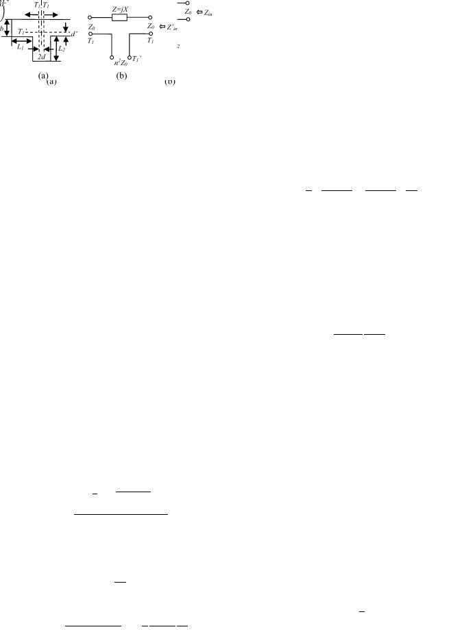
Fig. 2. (a) Series connection of two short-circuited waveguides and (b) its equivalent circuit.
271
Fig. 3. (a) Waveguide E-plane T-junction with two ports short-circuited. (b) The equivalent circuit of the E-plane T-junction with the reference planes defined in (a) [13].
A. Waveguide T-Junction Equivalent Circuit
The proposed design approach is presented starting from a single channel filter connected to a manifold, i.e., 

 in Fig. 1. An
  th order channel filter is attached to a waveguide T-junction with one port short-circuited. In order for the structure to behave as an

 order filter, the T-junction will serve as the first resonator. The distance between channel filter 1 to the manifold and the distance between the channel filter to the short circuit are designed to obtain the desired resonance frequency and the required coupling value. The channel filter is replaced with a short circuit in the following analysis. A simplified equivalent circuit in Fig. 2(a) showing two short-circuited waveguide sections in series connection is used for demonstration, which can be realized using E-plane waveguide T-junction as will be shown later. For H-plane T-junction, the equivalent circuit becomes a parallel connection of the two waveguide sections.
The impedance 
 at the common port in Fig. 2(a) is
(1)
where  is the characteristic impedance,
  is the propagation constant, ignoring loss of the waveguide, and
 and
and 
 are the lengths of the two waveguides, respectively. The short-circuited waveguide section with length of
 can be viewed as a coupling element with susceptance
 . Resonance occurs in the vicinity where


 or
or 


 , where


 and
and  is the guided wavelength at the resonance frequency. For this structure it is more convenient to find the coupling value and the resonance frequency using group delay [11]. This is acceptable since only a narrow band filter is used for each channel. The reflection coefficient at the common port can be found using (1) as
(2)
Therefore
(3)
The group delay  is given by
(4)
Let 


 and
and
(5)
Assume 

 at resonance, which coincides with the center frequency
  of the channel filter. The group delay at resonance can be derived as
When |
|
|
|
|
|
|
|
|
|
|
(6) |
|
|
|
|
|
|
|
|
|
|
||
|
|
|
or is odd, let |
. Then |
|||||||
. When |
|
|
|
or is even, let |
. |
||||||
|
. Equation (6) is thus reduced to |
|
|
||||||||
|
|
|
|
|
|
|
|
|
|
(7) |
|
|
|
|
|
|
|
|
|
|
|
||
The coupling value  is related to group delay as [12]
(8)
where BW is the bandwidth of the channel filter. For required coupling value  , length of the short-circuited waveguide can be calculated using (7) and (8). Note that when


 , the electrical length of the short-circuited waveguide section with length of
 is
is  . However when


 , the electrical length is

 .
. 
 is subsequently calculated ensuring the correct resonance frequency, i.e.,
(9)
The structure in Fig. 2 can be realized using waveguide E-plane junction. The lengths of each waveguide section need to be corrected taking into account the junction effect. The equivalent circuit of the T-junction [13] is used in Fig. 3, in which a waveguide E-plane junction with cross section area 

 is assumed.
The input impedance at the common port and reference plane  is changed to
(10)
in which
(11)

272 |
IEEE TRANSACTIONS ON MICROWAVE THEORY AND TECHNIQUES, VOL. 59, NO. 2, FEBRUARY 2011 |
Equations for calculation of 


 and
and 
 are given in [13]. The reflection coefficient at the common port in (2) and
(3) is modified accordingly as
(12)
(13)
It can be shown that the group delay at resonance can be estimated using
Let |
|
|
|
|
|
|
|
(14) |
|
|
|
|
|||||
|
|
|
|
. For design purpose, |
||||

 can be calculated using (7) and (8) for required coupling value
  .
. 
 is then determined ensuring the correct resonance
frequency, i.e., |
. An accurate estimate of group delay |
|
can then be found using (14). The waveguide lengths |
and |
|
in Fig. 3 are subsequently obtained by correcting |
and |
|
using (11). |
|
|
Once the desired coupling value and resonance frequency are determined, the waveguide junction can be used as the first resonator. The rest of the filter is designed following conventional filter design methodology [12].
B. Example of Single Channel Design
The waveguide with 


 mm and


 mm (WR75) is used in the following example. As shown in Table I, lengths
 and
and 
 are obtained using (7), (9) and (11) to realize the desired group delay


 , in which the resonance frequency


 GHz. In Table I(a),

 , i.e.,


 , while in Table I(b),

 , i.e.,


 . The group delay is then recalculated using (14) to obtain


 in Table I. The equivalent circuit of the E-plane T-junction in Fig. 3 is used for verification. The responses are plotted in Fig. 4 and the group delays and resonance frequencies obtained from the data in Fig. 4 are listed in the last two columns in Table I for comparison.
As can be seen, the group delay, hence coupling coefficient, can be readily adjusted varying lengths of the waveguides. Furthermore, (14) gives more accurate prediction of group delay. The difference in group delays and deviation of the resonance frequencies from 12 GHz are due to the approximation in the assumption of 

 at resonance. For the structure in Fig. 2(a) to resonate at
(15)
Solutions to (15) are complex and do not coincide with those from (7) and (9) precisely. However such inaccuracy can be easily corrected in practical use. The calculated waveguide section lengths serve as good initial values.
Using the initial values given in Table I(b), single channel filters connected to waveguide E-plane T-junctions are designed. The T-junctions are first simulated using mode-matching based full electromagnetic (EM) simulator. The S parameters of the 3-port waveguide T-junction networks are cascaded with circuit
Fig. 4. Group delay responses of the equivalent circuit of the E-plane T-junc- tion in Fig. 3. (a) the waveguide lengths are as case 1 to case 4 in Table I(a).
(b) the waveguide lengths are as case 5 to case 8 in Table I(b).
TABLE I
GROUP DELAY RESPONSE AS WAVEGUIDE LENGTHS CHANGE
model of channel filters using coupling matrices [14]. The waveguide lengths as well as coupling coefficients of the channel filter are optimized to ensure good impedance matching in the filter passband [15].
Taking the case 7 in Table I(b) as the initial value, a fourpole filter centered at 12 GHz with 36 MHz bandwidth is attached to the waveguide T-junction. After optimization, 


YU AND WANG: ENHANCED MICROWAVE MULTIPLEXING NETWORK |
273 |
Fig. 5. Comparison of the near-band responses of the four-pole filter with waveguide T-junction and a five-pole stand-alone filter.
TABLE II
OPTIMIZED WAVEGUIDE LENGTHS WITH CORRESPONDING GROUP DELAY
AND COUPLING VALUES FOR CHANNEL FILTERS CENTERED AT 12 GHZ AND
WITH 36 MHZ BANDWIDTH


 mm and


 mm to achieve 15 ns group delay at 12 GHz, which is equivalent to coupling value


 from
from
(8). The difference between the optimized waveguide lengths and the ones in Table I is largely caused by the difference in the model based on EM simulated S parameters of the waveguide junction and the model based on the equivalent circuit in [13]. Fig. 5 shows the common port return loss, i.e., 


 , and the transmission coefficient between the input of the channel filter and the common port, i.e.,


 , which clearly demonstrates that an extra pole is formed by the waveguide T-junction causing an additional real reflection zero to be brought into the passband. Therefore, a five-pole response results although the channel filter order is only four.
For comparison, the response of a five-pole stand-alone filter centered at 12 GHz with 36 MHz bandwidth is also plotted in Fig. 5. The coupling values of the five-pole filter are 


 , and input/output coupling


 . The near-band responses of the four-pole filter with waveguide T-junction and the five-pole stand-alone filter are identical.
In the following, all cases in Table I(b) are used for design of enhanced channel filters. The waveguide lengths after optimization, group delay at center frequency of 12 GHz and corresponding coupling value for 36 MHz bandwidth are listed in Table II. The near-band responses of 


 are compared in Fig. 6(a). It is seen that as the coupling value increases, the improvement in out-of-band rejection performance decreases. Although it is thus desirable to have small coupling value or large group delay, it becomes difficult to achieve good return loss as
Fig. 6. Comparison of responses of four-pole filters connected with waveguide T-junctions with different waveguide lengths. (a) Near-band responses of the
transmission coefficient |
. (b) Common port return loss |
. (c) out-of- |
|
band |
responses. |
|
|
shown in Fig. 6(b) with the design case 8 demonstrating behavior of a single-ended filter. Furthermore, it can be seen from Fig. 6 that improvement in the out-of-band rejection can still be achieved even though the return loss does not show five distinct peaks in the design cases 5 and 6. The out-of-band rejection responses in Fig. 6(c) show that the waveguide section with the length of 
 is causing an extracted pole at the frequency where it becomes a short-circuited quarter-wavelength resonator.
C. Enhanced Multiplexer Design Process
The proposed method is extended to multi-channel design. Connecting transmission lines are designed so that proper

274 |
IEEE TRANSACTIONS ON MICROWAVE THEORY AND TECHNIQUES, VOL. 59, NO. 2, FEBRUARY 2011 |
group delays, or coupling values, are achieved in the passband of each channel resulting in extra reflection zeros. Taking advantages of the existing waveguide manifold structure, the channel filter order is therefore effectively increased without additional resonators.
The general design steps include the following.
1)The manifold is first designed with the channels filters replaced with short circuits. As will be shown, lengths obtained following these steps give good initial values when single-ended channel filters are later attached to the manifold. It is also due to the fact that each channel filter behaves as a short circuit in its out-of-band. The distance between channel filters and the distance between each channel filter and the manifold are optimized to the desired group delay values in the passband of channel filters.
2)Check if the manifold dimensions are physically realizable in order to accommodate each channel filter. Repeat Step 1 when necessary.
3)Attach single-ended channel filters to the manifold.
4)All dimensions including channel to channel spacing, channel filter to manifold spacing, and internal dimensions of the channel filters are optimized to meet performance requirement [1].
As demonstrated in the previous section, small coupling value or large group delay results in higher level of performance enhancement. However large group delays are in general difficult to obtain. Besides the fact that it is difficult to achieve good return loss as shown in Fig. 6(b), the response becomes highly sensitive to changes in the manifold lengths for large group delays. It is found that as the number of channels increases the group delay should be designed to have a relatively low value over the passband of the multiplexer for practical realization. The amount of realizable delay may be limited by factors such as overall size constraint, the number of channels, center frequency of each channel and bandwidth of each channel. In most practical applications, a suitable solution can be found by optimization. Moreover, selected channels may be designed with higher level of performance enhancement.
D. Example of Non-Contiguous Multiplexer
To illustrate the effectiveness of the design process, a twochannel noncontiguous multiplexer is designed with the first channel filter centered at 12.75 GHz and the second channel filter centered at 12.53 GHz, each with 72 MHz bandwidth.
Manifold waveguide lengths 

 and
and 

 are as shown in Fig. 7, where

 and 2 for channel filter 1 and 2, respectively. Waveguide WR75 E-plane T-junctions are used. Comparison of conventional design techniques [1], [7] with the proposed design process has been conducted. Table III compares the values for manifold waveguide lengths obtained using both methods. Fig. 8 shows the group delay response of the common port return loss as the result of the optimization in step 1 of the design process with the channel filters replaced with short circuits. Two resonances at the corresponding center frequencies of the channel filters are clearly shown. The group delay response of the conventional design is also plotted in Fig. 8 for comparison. The common port return loss, i.e.,


 , the transmission coefficients between port
  and the common port, i.e.,


 , where
Fig. 7. Two-channel multiplexer.
TABLE III
MANIFOLD LENGTHS FOR A TWO-CHANNEL NON-CONTIGUOUS MULTIPLEXER
OBTAINED FROM CONVENTIONAL DESIGN APPROACH AND THE
PROPOSED METHOD
Fig. 8. Group delay response of the common port return loss with the channel filters replaced with short circuits for the two-channel noncontiguous multiplexer.
 is the port number and


 , are shown in Fig. 9. Comparing the


 curve of Fig. 9(a) of the conventional design, to the


 curve of Fig. 9(b) of the enhanced multiplexing network, it can be seen that Fig. 9(b) is essentially a combination of two five-pole filters whereas the conventional design is essentially a combination of two four-pole filters.
To clearly evidence the improvement in the performance of the each individual channel filter the transmission coefficients of Fig. 9 have been isolated and are comparatively shown in Fig. 10. For channel 1, in comparing the two curves in Fig. 10(a) it is obvious that the 


 curve of the new design is flat over a wider frequency range than the


 curve of the conventional design, thus the channel filter 1 of the enhanced multiplexer has a greater bandwidth. It also can be seen that this increased bandwidth is not achieved at the expense of rejection in the out of band region as it can be seen that the


 curve of the enhanced design has a much steeper rejection rate. The transmission coefficients for channel 2 experience similar improvement as shown in Fig. 10(b). Table IV summarizes the flatness of the transmission coefficients in the passband of each channel filter. The spec-

YU AND WANG: ENHANCED MICROWAVE MULTIPLEXING NETWORK
Fig. 9. Common port return loss, i.e., |
, the transmission coefficient be- |
tween port 2 and the common port, i.e., |
, and the transmission coefficient |
between port 3 and the common port, i.e., |
, of (a) the conventional design |
and (b) the enhanced multiplexing network. |
|
ifications are typically given based on normalized values of 


 that are normalized to the minimum value of


 in the passband. As can be seen from Table IV, for different flatness specification, the improvements range from 5.2 MHz to 6.9 MHz, which represent 7% to 9% improvement of the useable bandwidth. Such improvements are significant for satellite communication system, where less than 1 ppm/
 C frequency stability is required [3].
The extracted coupling matrices of the two five-pole (equivalent) channel filters as shown in Fig. 9(b) are
275
Fig. 10. Comparison of conventional and the enhanced multiplexing networks:
(a) the transmission coefficient for channel 1 and (b) the transmission coefficient for channel 2.
TABLE IV
FLATNESS OF THE TRANSMISSION COEFFICIENTS IN THE PASSBAND OF EACH
CHANNEL FILTER
TABLE V
CHANNEL FILTER LENGTHS OBTAINED FROM CONVENTIONAL DESIGN
APPROACH USING FIVE-POLE FILTERS AND THE PROPOSED METHOD
for channel 1 and
|
To further demonstrate the advantage of the proposed method, |
|
the multiplexer is designed with two five-pole channel filters |
|
using conventional method. The lengths of channel filters are |
for channel 2. |
compared in Table V. The channel filters are classical dual- |

276 |
IEEE TRANSACTIONS ON MICROWAVE THEORY AND TECHNIQUES, VOL. 59, NO. 2, FEBRUARY 2011 |
Fig. 12. Isometric view (ProE) of the fabricated multiplexer.
Fig. 11. Simulated results of the enhanced design of the four-channel contiguous multiplexer. (a) Transmission coefficient between the input port of each channel filter and the common port, i.e., 
 , where is the port number.
(b) Input return loss of each channel filter, i.e., 
 .
.
mode waveguide filters with the cavity diameter of 26.162 mm. The filter lengths of the enhanced multiplexer are about 2/3 of the five-pole channel filters since a five-pole filter requires three cavities whereas a four-pole file only requires two cavities.
E. Example of Contiguous Multiplexer With Measured Data
The enhanced multiplexing network design approach has been applied to a four-channel contiguous multiplexer. The channel filters are all four-pole filters centered at 3.902 GHz, 3.822 GHz, 3.742 GHz and 3.662 GHz, respectively, each with 72 MHz bandwidth. Half height WR229 waveguide E-plane T-junctions with 


 mm and


 mm are used in this example.
Fig. 11(a) shows the simulated transmission coefficient between the input port of each channel filter and the common port, i.e., 


 , where
  is the port number, of the enhanced design of the four-channel contiguous multiplexer. It is more convenient to view the additional resonance created by the manifold from the input return loss of channel filters, i.e.,


 . As shown in Fig. 11(b), all channel filters behave like five-pole filters although only four-pole filters are attached to the manifold.
The four-channel contiguous enhanced multiplexer has been built and tested. Fig. 12 shows the isometric view (ProE) of the fabricated multiplexer. As shown in Fig. 13, measurement results and simulation results agree very well for all channel fil-
Fig. 13. Measurement results of (a) the transmission coefficient and (b) the input return loss of each channel filter of the enhanced multiplexing network.
ters, validating the design methodology presented herein. Note that the resonances have shifted slightly during the tuning of the multiplexer, which is required to compensate manufacture tolerances. As a result, for channel 2, centered at 3.822 GHz, and channel 4, centered at 3.662 GHz, the additional resonances are not shown as clearly as in the simulation. For channel 4, a comparison between the measurement in Fig. 13(b) and the simulation in Fig. 11(b) shows that there is an extra resonance located at 3.69 GHz. For channel 2, the input return loss does not show five distinct peaks. However the improvement in the channel filter performance is preserved as the same design specifications are met using both simulation and measurement results.
III. CONCLUSION
A method for systematical design of enhanced microwave multiplexing network is presented in order to improve channel

YU AND WANG: ENHANCED MICROWAVE MULTIPLEXING NETWORK
performance. It is shown that interconnecting network such as manifold can be utilized to form an additional real reflection zero for channel filters through design and optimization of the distance between channel filters and the distance between each channel filter and the manifold. The channel filter order is therefore increased without additional resonators. Significant improvement in multiplexer performance is achieved without increase of size or weight. Waveguide E-plane T-junctions are used for demonstration of the design approach. However, the proposed method is not limited to waveguide manifold. It is applicable to all multiplexers using transmission lines to connect channel filters. Simulation and measurement results demonstrate the feasibility of such multiplexing networks.
REFERENCES
[1]R. Cameron and M. Yu, “Design of manifold coupled multiplexers,” IEEE Microw. Mag., pp. 46–59, Oct. 2007.
[2]C. Kudsia, R. Cameron, and W.-C. Tang, “Innovations in microwave filters and multiplexing networks for communications satellite systems,” IEEE Trans. Microw. Theory Tech., vol. 40, no. 6, pp. 1133–1149, Jun. 1992.
[3]S. Lundquist, M. Yu, D. Smith, and W. Fitzpatrick, “Kuband temperature compensated high power multiplexers,” presented at the Proc. 20th AIAA Int. Commun. Satellite Syst. Conf. Exhibit, Montreal, QC, Canada, May 2002.
[4]S. Lundquist, M. Mississian, M. Yu, and D. Smith, “Application of high power output multiplexers for communications satellites,” presented at the Proc. 18th AIAA Int. Commun. Satellite Syst. Conf. Exhibit, Oakland, CA, Apr. 2000.
[5]M. Yu, D. J. Smith, A. Sivadas, and W. Fitzpatrick, “A dual mode filter with trifurcated iris and reduced footprint,” in Proc. IEEE MTT-S Int. Microw. Symp. Dig., Seattle, WA, Jun. 2002, pp. 1457–1460.
[6]J. Zheng and M. Yu, “Rigorous mode-matching method of circular to off-center rectangular side-coupled waveguide junctions for filter applications,” IEEE Trans. Microw. Theory Tech., vol. 55, no. 11, pp. 2365–2373, Nov. 2007.
[7]A. E. Atia, “Computer-aided design of waveguide multiplexers,” IEEE Trans. Microw. Theory Tech., vol. 22, pp. 332–336, Mar. 1974.
[8]J. D. Rhodes and R. Levy, “A generalized multiplexer theory,” IEEE Trans. Microw. Theory Tech., vol. 27, no. 2, pp. 99–111, Feb. 1979.
[9]J. D. Rhodes and R. Levy, “Design of general manifold multiplexers,”
IEEE Trans. Microw. Theory Tech., vol. 27, no. 2, pp. 111–123, Feb. 1979.
[10]“Enhanced Microwave Multiplexing Network,” U.S. Patent 7397325 B2, Jul. 8, 2008.
[11]J. B. Ness, “A unified approach to the design, measurement, and tuning of coupled-resonator filters,” IEEE Trans. Microw. Theory Tech., vol. 46, no. 4, pp. 343–351, Apr. 1998.
[12]R. J. Cameron, C. M. Kudsia, and R. R. Mansour, Microwave Filters for Communication Systems: Fundamentals, Design and Applications. New York: Wiley, 2007.
[13]N. Marcuvitz, Waveguide Handbook The Institution of Electrical Engineers. Piscataway, NJ, 1986.
277
[14]A. E. Atia and A. E. Williams, “Narrow-bandpass waveguide filters,”
IEEE Trans. Microw. Theory Tech., vol. 20, no. 4, pp. 258–265, Apr. 1972.
[15]M. A. Ismail, D. Smith, A. Panariello, Y. Wang, and M. Yu, “EMbased design of large-scale dielectric-resonator filters and multiplexers by space mapping,” IEEE Trans. Microw. Theory Tech., vol. 52, no. 1, pt. 2, pp. 386–392, Jan. 2004.
Ming Yu (S’90–M’93–SM’01–F’09) received the Ph.D. degree in electrical engineering from the University of Victoria, Victoria, BC, Canada, in 1995.
In 1993, while working on his doctoral dissertation part time, he joined COM DEV, Cambridge, ON, Canada, as a Member of Technical Staff. He was involved in designing passive microwave/RF hardware from 100 MHz to 90 GHz for both space and ground based applications. He was also a principal developer of a variety of COM DEV’s core design and tuning
software for microwave filters and multiplexers, including computer aide tuning software in 1994 and fully automated robotic diplexer tuning system in 1999. His varied experience also includes being the Manager of Filter/Multiplexer Technology (Space Group) and Staff Scientist of Corporate Research and Development (R&D). He is currently the Chief Scientist and Director of R&D. He is responsible for overseeing the development of company R&D Roadmap and next generation products and technologies, including high frequency and high power engineering, electromagnetic based CAD and tuning for complex and large problems, novel miniaturization techniques for microwave networks. He is also an Adjunct Professor with the University of Waterloo, ON, Canada. He holds NSERC Discovery Grant from 2004–2013 with Waterloo. He has authored or coauthored over 90 publications and numerous proprietary reports. He holds 8 patents with 6 more pending.
Dr. Yu is an IEEE Distinguished Microwave Lecturer from 2010 to 2012. He is MTT Filter committee Chair (MTT-8) since 2010 and also served as Chair of TPC-11. He is an Associate Editor of IEEE TRANSACTIONS ON MICROWAVE THEORY AND TECHNIQUE. He was the recipient of the 1995 and 2006 COM DEV Achievement Award for the development a computer-aided tuning algorithms and systems for microwave filters and multiplexers.
Ying Wang (M’05) received the B.Eng. and the M.S. degrees in electronic engineering from Nanjing University of Science and Technology, Nanjing, China, and the Ph.D. degree in electrical engineering from University of Waterloo, Waterloo, ON, Canada, in 1993, 1996, and 2000, respectively.
From 2000 to 2007, she was with COM DEV, Cambridge, Ontario, Canada. As a Senior Member of Technical Staff, she was involved in development of CAD software for design, simulation and optimization of microwave circuits for space application. In
2007, she joined the Faculty of Engineering and Applied Science, University of Ontario Institute of Technology, Oshawa, ON, Canada, where she is currently an Assistant Professor. Her research interests include RF/microwave computer aided design, microwave circuits design and radio wave propagation modeling.