

диафрагмированные волноводные фильтры / bceeda2a-2d04-4dd6-a51f-95fe9af7329c
.pdfIEEE TRANSACTIONS ON MICROWAVE THEORY AND TECHNIQUES, VOL. 53, NO. 7, JULY 2005 |
2309 |
Verification of First Circulation Conditions
of Turnstile Waveguide Circulators
Using a Finite-Element Solver
Joseph Helszajn, Fellow, IEEE, and John Sharp, Senior Member, IEEE
Abstract—One means of adjusting the first circulation condition of any waveguide circulator is to have recourse to a finite-element (FE) solver. The purpose of this paper is to do so for each of the three possible geometries of the turnstile waveguide circulator. A complete statement of the first circulation condition also requires one of the susceptance slope parameter of the junction. This quantity is separately evaluated. The resonators under consideration are the side and apex coupled half-wave-long prism structures open circuited at each flat face and the conventional cylindrical geometry. The classic  -plane turnstile circulator using a prism resonator is also dealt with. The agreement between the existing literature and the FE adjustment is excellent.
Index Terms—Circulators, finite elements (FEs), gyromagnetic resonators, nonreciprocal networks, turnstile junctions.
I. INTRODUCTION
ONE PROBLEM met in the construction of waveguide circulators is that of deducing the so-called first circulation condition of the junction. It is ideally met provided its degenerate counter-rotating eigennetworks and that of its in-phase one are commensurate. It coincides with the maximum power transfer or minimum reflection coefficient of the junction and essentially determines the frequency of the related circulator [1]–[6]. The so-called second circulation condition merely involves the removal of the degeneracy between the two counter-rotating eigennetworks. One classic configuration is that of a half-wave-long cylinder open-circuited on both its flat faces supported by dielectric supports on the axis of three  -plane rectangular waveguides [7]–[13]. It has its origin in the original turnstile junction circulator [1]. Another is that of either an apex or side-coupled half-wave-long prism arrangement [14]–[17]. The various geometries under consideration are depicted in Fig. 1. Each configuration has been experimentally adjusted one way or another in the open literature. In the cylindrical geometry, the frequency of the degenerate eigennetworks is controlled by the dimensions of the cylinder and that of the in-phase one by the details of the dielectric spacer [9], [10], [18], [19]. The frequency of the degenerate counter-rotating eigennetworks is also affected to some degree by the spacer. The experimental adjustment of this sort of junction is, in practice,
Manuscript received June 28, 2004; revised September 28, 2004.
J. Helszajn is with the Department of Electrical and Electronic Engineering, Heriot Watt University, Edinburgh EH14 4AS, U.K.
J. Sharp is with the School of Engineering, Napier University, Edinburgh EH 10 5DT, U.K. (e-mail: j.sharp@napier.ac.uk).
Digital Object Identifier 10.1109/TMTT.2005.850443
Fig. 1. Schematic diagram of turnstile junction using apex coupled prism, side-coupled prism, and cylindrical resonators.
tedious and labour intensive. The purpose of this paper is to compare the available data on the cylindrical geometry with that obtained by having recourse to a commercial three-dimensional finite-element (FE) solver (Ansoft’s High Frequency Structure Simulator (HFSS), version 8). The agreement is excellent. The two  -plane arrangements using prism resonators are dealt with separately [14]–[17]. Still another classic geometry is the
  -plane junction using a quarter-wave-long prism or disk resonators [20], [21]. It is also dealt with. Another important quantity that is embodied in the first circulation condition is the susceptance slope parameter of a weakly magnetized junction [22]–[24]. This quantity may also be computed from the frequency response of the degenerate eigennetworks [25]. The correlation between the existing experimental results in the open literature and the FE calculations undertaken in this study suggests that the latter formulation is more than adequate for engineering purposes.
II. FIRST CIRCULATION CONDITION OF JUNCTION CIRCULATOR
The adjustment of the three-port circulator is a classic two-step procedure. The first step coincides with the maximum power transfer condition of the junction; the second merely involves the splitting of the degeneracy between the counter-ro- tating eigenvalues of the junction.
0018-9480/$20.00 © 2005 IEEE

2310 IEEE TRANSACTIONS ON MICROWAVE THEORY AND TECHNIQUES, VOL. 53, NO. 7, JULY 2005
The relationships between the scattering parameters and re- |
|
flection eigenvalues of the reciprocal junction are given in the |
|
usual way by [1]–[4]. |
|
(1) |
|
(2) |
|
where is an in-phase and is a degenerate counter-rotating |
|
one-port reflection coefficient. The eigenvalues in a three-port |
|
reciprocal junction are reflection coefficients associated with the |
|
three possible terminal conditions, which produce identical re- |
|
flections at each port. One such port condition coincides with |
|
in-phase voltage settings at each pair of terminals. The other |
|
two coincide with counter-rotating field settings at the same ter- |
|
minals. In a reciprocal junction, the latter so-called eigenvalues |
|
are degenerate. Another property of the reflection eigenvalues is |
|
that these, in a lossless junction, have a unit amplitude and are |
|
only distinguished from each other by a phase angle. |
|
The ideal passband frequency coincides with the conditions |
|
(3) |
Fig. 2. Eigenvalue diagrams of definitions of passband frequencies of |
|
|
(4) |
reciprocal three-port junctions. |
The passband frequency in a nonideal situation is defined by [6]
(5)
where  and
and 
 are the one-port impedances associated with each eigenvalue.
The three possibilities are, in practice, defined by the angle of

 . This is indicated in Fig. 2. While the two nonideal conditions still produce a passband frequency, the responses of these do not produce symmetrical frequency excursions about the center frequency. This is of some importance in the development of high-quality quarter-wave coupled circulators with Chebyshev frequency responses.
III. OPERATION OF TURNSTILE CIRCULATOR USING
CYLINDRICAL OR PRISM RESONATORS
One important classic waveguide three-port junction circulator is the turnstile one. The adjustment of this sort of circulator is a classic eigenvalue problem. The first circulation condition of the device corresponds with that for which the in-phase reflection eigenvalue is out-of phase with its degenerate counter-rotating ones. It coincides, in practice, with the maximum power transmission or minimum reflection coefficient at port 1 of the junction with the other two suitably terminated in matched loads. The three possible geometries using half-wave- length-long cylindrical prism resonators supported by dielectric spacers are illustrated in Fig. 1. The experimental adjustment of this sort of junction is, in practice, tedious and labour intensive. The second circulation condition involves the removal of the degeneracy of the counter-rotating eigenvalues by the gyrotropy of the gyromagnetic insulator.
The following scattering parameters of this arrangement are again a standard result in the literature [1]–[3]:
(6)
(7)
(8)
where
(9)
The turnstile junctions dealt with here all rely on a Faraday rotation effect along the axis of the resonators. It is obtained by removing the degeneracy between the counter-rotating eigenvalues by the application of the gyrotropy. One solution is obtained with
(10)
(11)
(12)
An ideal solution is obtained with
(13)
(14)
The first of these two conditions, in the case of the turnstile circulator, is governed by the first circulation condition outlined

HELSZAJN AND SHARP: VERIFICATION OF FIRST CIRCULATION CONDITIONS OF TURNSTILE WAVEGUIDE CIRCULATORS USING FE SOLVER |
2311 |
Fig. 3. Turnstile resonators using half-wave-long and single and pairs of quarter -wave-long resonators.
in Section II. The second involves a Faraday effect up and down the gyromagnetic rod. The overall angle of rotation is
rad |
(15) |
The ideal angle of rotation is in keeping with (14) 


 . The main endeavour of this study is, however, the so-called first circulation condition specified in Section II.
IV. OPERATION OF TURNSTILE CIRCULATORS
One classic turnstile circulator relies for its operation on a half-wave-long cylindrical resonator open circuited at each end, supported by suitable dielectric spacers, as depicted in Fig. 1(a). A variation of this geometry, which is equivalent in every way, consists of a pair of quarter-wave-long resonators open circuited at one end and short circuited at the other. Still another consists of a single quarter-wave resonator open circuited at one end and short circuited at the other. The three possibilities are shown in Fig. 3. In these sorts of geometries, the frequency of the degenerate eigennetworks is controlled by the electrical length of the cylinder and that of the in-phase mode by the details of the dielectric spacer. The former adjustment places a magnetic wall on the cylindrical plane of the resonator and the latter one place an electric wall at the same plane. The modes are the 


 and
and 


 ones, respectively. The frequencies of the degenerate counter-rotating eigennetworks are also affected to some degree by the spacer. These sorts of geometries are described by a gap factor

 , an axial resonator length (
 or
or 
 ), and the
Fig. 4. Frequency responses of in-phase and degenerate counter-rotating eigenvalues of a turnstile junction using a single disk resonator (R=L = 4:259,
R = 4:125 mm k = 0:7; 0:8; 0:9).
radius or side dimension of the resonator ( or
or  ). It produces a unique gap factor for each and every value of radius or side dimension of the resonator. The filling factor of the junction is defined by
All the experimental data on the first circulation condition of waveguide circulators referred to in this paper apply to junctions employing demagnetized ferrite resonators. In order to account for this feature in this study, a demagnetized ferrite geometry is employed throughout as follows:
(16)
 is the saturation magnetization


 ,
,  is the radian frequency (radians per second), and
  is the gyromagnetic ratio (2.21
  10
10 rad/s/A/m).
V. FIRST CIRCULATION CONDITION OF TURNSTILE JUNCTION
USING CYLINDRICAL RESONATORS
The first and second circulation conditions of the junction are both necessary and sufficient for the adjustment of the classic circulator. The first condition, shown in Fig. 2, is the main endeavour of this paper, is fixed by whether the geometry under discussion is a waveguide, stripline, or some other type of circulator. This section is restricted to any one of the three possible arrangements of the so-called turnstile circulator using cylindrical resonators. It is necessary, as with all software-based designs, to initialize the process with some realistic initial parameters. Fortunately, enough information is generally already available in the open literature in order to do so.
Fig. 4 indicates the in-phase and counter-rotating reflection eigenvalues of one junction for parametric values of a gap factor
2312 |
IEEE TRANSACTIONS ON MICROWAVE THEORY AND TECHNIQUES, VOL. 53, NO. 7, JULY 2005 |
Fig. 6. Topologies waveguide turnstile junctions using apex and side-coupled prism resonators.
Fig. 5. Frequency responses of in-phase and degenerate counter-rotating eigenvalues of a turnstile junction using a single disk resonator (R=L = 4:259,
R = 4:4 mm k = 0:70; 0:8; 0:9).
for a single quarter-wave-long structure. The aspect ratio of the resonator is 


 and the radius is 4.125 mm. These sorts of displays may be employed to fix the first circulation condition of the adjustment. The required solution, in this instance, is at 9.35 GHz and coincides with a filling factor of 0.80. The frequency of the device is separately set by varying either the length or the radius of the resonator. Fig. 5 depicts the adjustment of this class of circulator for another radius. The optimum frequency is now 9.4 GHz.
The sort of data depicted in these illustrations is obtained by evaluating the transmission and reflection scattering parameters of the junction at the terminals of the resonator as a preamble to processing the reflection eigenvalues. The physical variables utilized in obtaining this data have been experimentally obtained elsewhere [5].
VI. ADJUSTMENT OF TURNSTILE JUNCTION
USING PRISM RESONATORS
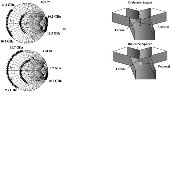
The classic turnstile circulator using a prism resonator may be realized in one of six ways. The side-coupled arrangement may be based on the use of a half-wave-long configuration open circuited at each flat face or on one or two quarter-wave-long geometries open circuited at one flat face and short circuited at the other. While the gain bandwidth and frequency of each resonator are essentially the same, each has a different value of the susceptance slope parameter. A similar situation is met in connection with the apex-coupled configuration. The two configurations under discussion are indicated in Fig. 6. Fig. 7 illustrates the effect of the filling factor on the apex-coupled structure using a pair of coupled resonators. It is again in excellent agreement with historic experimental data in the literature [17]. Fig. 8 gives the corresponding result in the case of the side-cou- pled geometry.
Fig. 7. Frequency responses of in-phase and degenerate counter-rotating eigenvalues of a turnstile junction using an apex coupled prism resonator
(A=L = 4:5, k = 0:73; 0:8).
VII. POST RESONATOR
The post resonator at the junction of three waveguides is one geometry for which the ideal relationship between the in-phase and degenerate counter-rotating reflection eigenvalues cannot be met. The structure under consideration is illustrated in Fig. 9. The Smith chart solution is depicted in Fig. 10. One means of idealizing the first circulation condition of this geometry is to introduce a thin metal post on the axis of the junction.
VIII.  -PLANE TURNSTILE JUNCTION CIRCULATOR USING
SINGLE PRISM RESONATOR
Another common waveguide junction circulator is the  -plane geometry using a single prism resonator [20], [21]. Fig. 11 depicts the structure under consideration. Its eigenvalue

HELSZAJN AND SHARP: VERIFICATION OF FIRST CIRCULATION CONDITIONS OF TURNSTILE WAVEGUIDE CIRCULATORS USING FE SOLVER |
2313 |
Fig. 8. Frequency responses of in-phase and degenerate counter-rotating eigenvalues of a turnstile junction using a side coupled prism resonator.
(A=L = 4:5, k = 0:73; 0:8).
Fig. 9. Schematic diagram of post resonator at the junction of three waveguides.
Fig. 11. Topology of E-plane junction circulator using single prism resonator.
Fig. 12. Comparison between calculated and experimental passband center frequencies of E-plane junction circulator using a single side-coupled prism resonator (A = 6:37 mm, A=L = 2:24).
Fig. 10. Frequency responses of in-phase and counter-rotating eigenvalues of degenerate post resonator.
diagram differs from that of the  -plane geometry in that its in-phase eigenvector produces an electric rather than a magnetic wall on the axis of the junction.
This boundary condition is normally associated with a stopband instead of the passband met in connection with the  -plane geometry. In order to avoid this situation, the opening of the junction is often restricted so that it is cut off for this eigenvalue [20]. Some experimental data illustrating the relationships between the bandpass center frequency and the filling factor for one value of aspect ratio

 is reproduced
in Fig. 12 [21]. Also superimposed on this data are some calculations obtained here using an FE solver. A Smith chart representation of the in-phase and degenerate counter-rotating eigenvalues are separately indicated in Fig. 13. It is apparent that this solution does not coincide with electric and magnetic walls of the eigenvalues at the terminals of the resonator. The center frequency of the junction does, however, coincide with the definition of the passband frequency specified in (5).
IX. SUSCEPTANCE SLOPE PARAMETER
The first and second circulation conditions of the junction circulator are sufficient to describe its midband frequency and its gyrator impedance, but not its frequency response. One means of quantifying the bandwidth of the junction is to invoke the susceptance slope parameter of either its reciprocal or nonreciprocal circuits. It coincides, provided the frequency behavior of the in-phase mode eigenvalue can be neglected compared to

2314 |
IEEE TRANSACTIONS ON MICROWAVE THEORY AND TECHNIQUES, VOL. 53, NO. 7, JULY 2005 |
Fig. 14. Susceptance slope parameter of an H-plane turnstile junction circulator employing a single disk resonator (---- locus of values that give ideal eigenvalue adjustment).
Fig. 13. In-phase and counter-rotating reflection eigenvalues of the E-plane using single prism resonator (A = 6:73 mm, A=L = 2:24, " = 10:3,
0M = 0:2100 T).
those of the degenerate ones, with that of the latter networks. This quantity may be extracted from the rim of the Smith chart in the sort of diagrams met in connection with its first circulation condition
(17)
The result for one cylindrical arrangement is
This result may be compared with the standard method based on frequency response of the reflection coefficient 

 or voltage standing-wave ratio (VSWR)


(18)
Taking the 7-dB frequency points by way of an example gives
Fig. 14 illustrates the connection between the filling factor 

 and the susceptance slope parameter


 at the first circulation condition for parametric values of

 .
.
X. SPLIT FREQUENCIES OF TURNSTILE CIRCULATOR
The second adjustment of the turnstile circulator is outside the remit of this study. It nevertheless maybe worthwhile to use the commercial FE package to evaluate the split frequencies of the gyromagnetic resonator. A knowledge of these frequencies is sufficient to characterize the quality factor of the complex gyrator circuit of the circulator
(19)
Fig. 15. Split frequencies of a turnstile junction using a single disk saturated gyromagnetic resonator for values of the magnetization between 0– 0.1600 T.
One shortcoming of the software at hand is that it does not cater to a partially magnetized problem region. In order to produce a relationship between magnetization and splitting, it is, therefore, necessary to join points corresponding to different values of saturation magnetization. One consequence of this difficulty is that the effective permeability of the gyromagnetic resonator varies with the value of magnetization and, therefore, so does the midfrequency of the frequency response. In practice, the center frequency increases as the saturation magnetization increases. The effective permeability for a saturated material is, as is well known, given by
(20)
Fig. 15 indicates some typical frequency responses with 

 as a parameter. It is of note that the junction does not, in general, display discrete split frequency lines below the degree-1 circulation solution. This is a general result. It is of separate note that above the degree-1 condition, the return loss

HELSZAJN AND SHARP: VERIFICATION OF FIRST CIRCULATION CONDITIONS OF TURNSTILE WAVEGUIDE CIRCULATORS USING FE SOLVER |
2315 |
at the split frequencies coincide with the 9.5-dB frequencies of the display.
XI. CONCLUSIONS
The turnstile waveguide circulator may be realized in one of nine configurations. The adjustment of any one of them is, in practice, a tedious activity. This paper has demonstrated good correlation between an FE adjustment of its first circulation condition and historic data in the open literature. While this condition is historically referred to as the first of two necessary requirements in itself, it is not sufficient in that, strictly speaking, it is also necessary to have a statement about the frequency response of the junction. Good agreement between experiment and calculations has also been demonstrated in this instance. The post resonator at the junction of three waveguides has been separately dealt with. The classic  -plane turnstile circulator using a prism resonator has also been dealt with.
REFERENCES
[1]T. Schaug-Patterson, “Novel design of a three-port circulator,” Norwegian Defence Res. Establishment, Bergen, Norway, Rep. R-59, Jan. 1–10, 1958.
[2]B. A. Auld, “The synthesis of symmetrical waveguide circulators,” IRE Trans. Microw. Theory Tech., vol. MTT-7, no. 4, pp. 238–246, Apr. 1959.
[3]U. Milano, J. H. Saunders, and L. E. Davis, Jr., “A Y-junction stripline circulator,” IRE Trans. Microw. Theory Tech., vol. MTT-8, no. 3, pp. 346–351, May 1960.
[4]C. G. Montgomery, R. H. Dicke, and E. M. Purcell, Principles of Microwave Circuits. New York: McGraw-Hall, 1948.
[5]J. Helszajn and J. Sharp, “Adjustment of in-phase mode in turnstile circulator,” IEEE Trans Microw. Theory Tech., vol. MTT–33, no. 4, pp. 339–343, Apr. 1985.
[6], “Post dielectric resonator at the junction of three rectangular waveguides: Calculation and measurements,” Proc. Inst. Elect. Eng., pt. H, vol. 150, pp. 90–96, Apr. 2003.
[7]B. Owen and C. E. Barnes, “The compact turnstile circulator,” IEEE Trans. Microw. Theory Tech., vol. MTT-18, no. 12, pp. 1096–1100, Dec. 1970.
[20]M. Omori, “An improved E-plane waveguide circulator,” in IEEE MTT-S Inl. Microwave Symp. Dig., 1968, pp. 228–228.
[21]J. Helszajn, B. Tsounis, and P. Papaionnou, “Mode chart and susceptance slope parameter of an E-plane circulator using prism resonators,” Proc Inst. Elect. Eng., pt. H, pp. 23–28, Feb. 1999.
[22]J. Helszajn and F. C. F. Tan, “Susceptance slope parameter of waveguide partial-height ferrite circulators,” Proc. Inst. Elect. Eng., vol. 122, no. 72,
pp.1329–1332, Dec. 1975.
[23]J. Helszajn and J. Sharp, “Resonant frequencies, Q-factor, and susceptance slope parameter of waveguide circulators using weakly magnetized open resonators,” IEEE Trans. Microw. Theory Tech., vol. MTT-31, no. 6, pp. 434–441, Jun. 1983.
[24]J. Helszajn, “A unified approach to lumped element, stripline and waveguide junction circulators,” Proc. Inst. Elect. Eng., pt. H, vol. 1, no. 1,
pp.18–26, Sep. 1976.
[25]J. Helszajn and J. Sharp, “Frequency responses of quarter-wave coupled reciprocal stripline junctions,” Microwave Eng. Europe, pp. 29–35, Mar./Apr. 2003.
Joseph Helszajn (M’64–SM’87–F’92) received the M.S.E.E. degree in electrical engineering from the University of Santa Clara, Santa Clara, in 1964, the Ph.D. degree from The University of Leeds, Lees, U.K., in 1969, for his work on spinwave instabilities in magnetic insulators at large radio frequency signal level, the D.Sc. degree from Heriot-Watt University, Edinburgh, U.K., in 1974, for his early collected works on gyromagnetic devices and circuits, and the D.Eng. from The University of Leeds, in 1995, for his ongoing works.
He is an international authority on nonreciprocal microwave circuits and devices. He gained his first qualification at what is now the University of North London and then undertook National Service in the Royal Air Force (1955–1957). He acquired his early industrial experience with Raytheon Inc., Sylvania Electric Inc., and Microwave Associates Inc. on the east and west coasts of the U.S. In 1971, he joined the Department of Electrical and Electronic Engineering, Heriot-Watt University, at which time he was instrumental in laying the foundation of what is now its Microwave Laboratory. In 1982, he became a personal Chair in microwave engineering with the Department of Electrical and Electronic Engineering, Heriot-Watt University. During part of the 1987 academic year, he was a Distinguished Visiting Professor with Arizona State University. He has authored 12 engineering text books, which have unified the important nonreciprocal branch of microwave engineering:
[8]B. Owen, “The identification of modal resonances in ferrite loaded Principles of Microwave Ferrite Engineering (New York: Wiley, 1969), waveguide junction and their adjustment for circulation,” Bell Syst. Non-reciprocal Microwave Junctions & Circulators (New York: Wiley, 1975)
Tech. J., vol. 51, no. 3, Mar. 1972. |
(Chinese translation in press), Passive and Active Microwave Circuits (New |
[9]E. J. Denlinger, “Design of partial-height ferrite waveguide circulators,” York: Wiley, 1978) (hardback reprint, 1980), (Russian translation, 1981), YIG IEEE Trans. Microw. Theory Tech., vol. MTT-22, no. 8, pp. 810–813, Resonators and Filters (London, U.K.: Wiley, 1985), Ferrite Phase Shifters
Aug. 1974.
[10]J. Helszajn, “Common waveguide circulator configurations,” Electron. Eng., pp. 66–68, Sep. 1974.
[11], “Design of waveguide circulators with Chebyshev characteristics using partial-height resonators,” IEEE Tran. Microw. Theory Tech., vol. MTT-32, no. 8 , pp. 908–917, Aug. 1984.
[12]Y. Akaiwa, “Operation modes of a waveguide Y-circulator,” IEEE Trans. Microw. Theory Tech., vol. MTT-22, no. 11, pp. 954–959, Nov. 1974.
[13], “A numerical analysis of waveguide H-plane Y-junction circulators with circular partial-height ferrite post,” J. Inst. Electron. Commun. Eng. Jpn., vol. E61, pp. 609–617, Aug. 1978.
[14]F. M. Aitken and R. McLean, “Some properties of the waveguide Wye circulator,” Proc. Inst. Elect. Eng., vol. 110, no. 2, pp. 256–260, 1963.
[15]Y. Akaiwa, “Mode classification of triangular ferrite post for Y-cir- culator,” IEEE Trans. Microw. Theory Tech., vol. MTT-25, no. 1, pp. 59–61, Jan. 1977.
[16]G. Riblet, J. Helszajn, and B. O’Donnell, “Loaded Q-factors of partial height and full-height triangular resonators for use in waveguide circulators,” in Proc. Eur. Microwave Conf., 1979, pp. 420–424.
[17]J. Helszajn, “Adjustment of degree-2 H-plane waveguide turnstile circulator using prism resonator,” Microwave Eng. Europe, pp. 35–48, Jul. 1999.
[18]J. Helszajn and F. C. F. Tan, “Mode charts for partial-height ferrite waveguide circulators,” Proc. Inst. Elect. Eng., vol. 122, no. 1, pp. 34–36, Jan. 1975.
[19], “Design data for radial waveguide circulators using partial-height ferrite resonators,” IEEE Trans. Microw. Theory Tech., vol. MTT-23, no. 3, pp. 288–298, Mar. 1975.
and Control Devices (London, U.K.: McGraw-Hill, 1989), Synthesis of Lumped Element, Distributed and Planar Filter Circuits (London, U.K.: McGraw-Hill, 1990), Microwave Engineering; Passive, Active and Non-Reciprocal Circuits
(London, U.K.: McGraw-Hill, 1992) (paperback reprint, 1993), Microwave Passive Planar Circuits and Filters (London, U.K.: Wiley, 1993) (hardback reprint, 1994), Green’s Function, Finite Elements and Microwave Planar Circuits (London, U.K.: Wiley, 1996), Theory and Practice of Waveguide Junction Circulators (London, U.K.: Wiley, 1998), Ridge Waveguide and Passive Microwave Components (London, U.K.: IEE Press, 2000), The Stripline Circulator: Theory and Practice (New York: Wiley, 2004). He has authored or coauthored over 150 papers in both the industry and university sectors. Until recently, he was one of two Honorary Editors for over 18 years of the
Proceedings of the Institution of Electrical Engineers (Part H: Microwaves, Antennas and Propagation). His recent position in industry (as a consultant to Ferranti, M.o.D. contract worker, and international consultant to a number of major North American companies) has been recognized by his appointments as Honorary Vice-President of Research of Apollo Microwave, Montreal, QC, Canada, and as Director of Eurowave Ltd., Edinburgh, U.K.
Prof. Helszajn is a Chartered Engineer (C.Eng.) in the U.K. He is a Fellow of the Institution of Electrical Engineers (IEE), U.K., the Royal Society of Arts, the City and Guilds Institute, the Royal Society of Edinburgh, and the Royal Academy of Engineering. He is a member of the Editorial Board of the IEEE TRANSACTIONS ON MICROWAVE THEORY AND TECHNIQUES. He was the recipient of the 1995 IEE J. J. Thomson Medal. He was appointed an Officer of the Order of the British Empire (OBE) in the 1997 Queen’s Birthday Honors List. He was also the recipient of a 2004 Napier University Honorary Doctorate of Engineering Degree (D.Eng.).

2316 |
IEEE TRANSACTIONS ON MICROWAVE THEORY AND TECHNIQUES, VOL. 53, NO. 7, JULY 2005 |
John Sharp (M’83–SM’87) was born in Bangour, Scotland, in 1954. He received the B.Sc. (Hons.), M.Sc., and Ph.D. degrees from Heriot Watt University, Edinburgh, U.K., in 1975, 1983, and 2004 respectively.
He is currently a Reader in microwave engineering and Deputy Head of the School of Engineering, Napier University, Edinburgh, U.K. Over the last 25 years, he has developed courses and projects in microwave and RF engineering for undergraduates and post graduates. These courses have been
delivered both in academic and industrial settings and have included “Electromagnetic Field Theory,” “Communication Engineering, Satellite Systems,” and “Microwave and Optical Engineering.” He has been a consultant numerous times for local industry. He has also had consultancies with numerous major communication and microwave companies including GEC Marconi Avionics, BAE Systems, Motorola, RACAL-MESL, Hewlett-Packard, and AXON Cables. He has undertaken several industrial, Department of Trade and Industry (DTI), Ministry of Defence (MOD), and Engineering and Physical Sciences Research Council (EPSRC) funded projects. His particular specialization is concerned with all aspects of nonreciprocal devices with special attention to waveguide circulators. He is a reviewer for the Proceedings of the Institution of Electrical Engineers (Part H: Microwave Antennas and Propagation) and Electronic Letters. He is also a pre-publication reviewer of specialist texts for several publishers.
Dr. Sharp is a Chartered Engineer in the U.K. He is a member of the Institute of Learning and Teaching. He is a Fellow of the Royal Society of Arts and the Institution of Electrical Engineers (IEE), U.K. He has served on committees of the IEE (E12 Microwave Devices and Techniques and S8 Electromagnetics).