

диафрагмированные волноводные фильтры / c6a22f16-b1a5-4ceb-ad24-29f36f29706e
.pdfThis article has been accepted for publication in a future issue of this journal, but has not been fully edited. Content may change prior to final publication. Citation information: DOI 10.1109/LAWP.2019.2937769, IEEE Antennas and Wireless Propagation Letters
AWPL-07-19-1368 |
1 |
S-Band Compact Microstrip Full Duplex Tx/Rx Patch Antenna with High Isolation
Amr H. Hussein, Haythem H. Abdullah, Mahmoud A. Attia, and Alaa M. Abada
Abstract— In this paper, a new design for two-port transmit/ receive full-duplex microstrip patch antenna for 4G and 4G advanced communication systems is introduced. The proposed duplex antenna consists of a single gear-shaped radiating patch for bidirectional radiation. The isolation between transmit and receive ports is achieved by using frequency space filtering technique where two omega-shaped defected ground structure (DGS) based-band pass filters (BPF) are created at transmit and receive ports of the antenna. The antenna achieves a compact size of ( × ) , high isolation larger than − at the transmit frequency = . and larger than − at the receive frequency = . , and small Tx-Rx frequency space ratio = . . Also, the proposed structure can cover the entire S-band from to by scaling the sizes of the omega-shaped DGSs to control the resonance frequencies of the embedded BPFs before fabrication. Furthermore, the embedded
BPFs have sharp cutoff characteristics, high selectivity, and channel bandwidth of about ≤ at | | = | | = −. The simulation and measurement results are highly
coincided.
Index Terms— Band Pass Filter (BPF), Defected Ground Structure (DGS), Full Duplex Microstrip Patch Antenna, S-Band.
I.INTRODUCTION
RECENTLY where communication technology is growing precipitately, the need for the hardware of compact size and high efficiency becomes a critical issue. Also, full-
duplex or simultaneous transmission and reception is a serious mode of communications. This kind of modes can rise the spectral efficiency and doubles the throughput of the system. Full-duplex or simultaneous transmission and reception can be realized using full-duplex antenna systems. But, it requires high ports isolation and selectivity. In this case, due to their important role in many communication systems, duplexers are the type of microwave circuit elements that can help to achieve this goal. Essentially, the duplexers are built using microstrip technology which have been widely used in multiservice and multiband communications. The basic role of a duplexer is to route the signal from the transmitter to the antenna and from the
This paper is submitted for review in April, 26, 2019. This work is done under the contract between the national authority of remote sensing and space sciences, Egypt and the electronics research institute in an S-band transceiver project for cube sat.
A. H. Hussein is with the Faculty of Engineering, Tanta University, Electronics and Electrical Communications Engineering Dept.,Tanta 1600, Egypt (e-mail: amrvips@yahoo.com; amr.abdallah@f-eng.tanta.edu.eg).
H. H. Abdullah is with the Electronics Research Institute, Joseph Tito St, Huckstep, Qism El-Nozha, Cairo Governorate (e-mail: haythm_eri@yahoo.com).
antenna to the receiver [1, 2]. In [3], a full-duplex microstrip antenna array system based band-pass filtering is introduced. Two different dimensions microstrip resonators are coupled to the two wide-band radiating patches via two H-slot resonators which constitute two BPFs tuned at the transmitting and receiving frequencies. Such structure provides good bands isolation with high selectivity. But, its isolation does not exceed −30 dB and the realized frequency space ratio is relatively high and equals = 0.23 which is defined as the ratio between the Tx & Rx frequency spacing ∆ = ( − ) and the central frequency ( + )⁄2 [3].
= ( |
− )⁄( |
+ )⁄2 |
(1) |
|
|
|
|
|
|
where and are the transmitting and receiving frequencies, respectively.
In [4], a self diplexing bow-tie shaped slot antenna backed on a Substrate Integrated Waveguide (SIW) cavity is introduced. Two separate feed lines are utilized to excite the SIW cavity to resonate at the transmitting and receiving frequencies. This well-known structure produces a high gain antenna with a unidirectional radiation pattern. But, it provides high-frequency space ratio = 0.22 with relatively low Tx-Rx isolation of 22 dB. In [5], a dual-band microstrip patch antenna is introduced for diplixing operation. The antenna transceiver is realized on three layers formed as an air layer sandwiched between two FR4 substrates having the same permittivity = 4.4 and different thickness. Stepped impedance microstrip line resonator is used to achieve isolation between the two ports at the operating bands. However, the antenna suffered from highfrequency space ratio = 0.74 and poor isolation values which equal 20 dB and 28 dB at the low band and high band, respectively. A square microstrip patch antenna for GPS applications has been introduced in [6]. A single-feed slotted patch structure is used to reduce the frequency space ratio of two bands. But, the antenna size is large compared to the aforementioned work. In this paper, a new design for compact dual ports full duplex Tx/Rx patch antenna for S-band is introduced. It is based on the utilization of defected ground structure (DGS) technique to implement the required high selectivity BPFs at the two ports of the antenna. Also, it
M. A. Attia is with the Faculty of Engineering, Tanta University, Electronics and Electrical Communications Engineering Dept.,Tanta 1600, Egypt (mahmoudahmedattia@yahoo.com).
A. M. Abada is with the Electronics and Electrical Communications Department, High Institute of Engineering and Technology, Kafr El-Sheikh, Egypt.
1536-1225 (c) 2019 IEEE. Personal use is permitted, but republication/redistribution requires IEEE permission. See http://www.ieee.org/publications_standards/publications/rights/index.html for more information.

This article has been accepted for publication in a future issue of this journal, but has not been fully edited. Content may change prior to final publication. Citation information: DOI 10.1109/LAWP.2019.2937769, IEEE Antennas and Wireless Propagation Letters
AWPL-07-19-1368 |
2 |
provides high isolation between the transmit and receive ports with a small frequency space ratio of about 0.0245.
II.PROPOSED FULL DUPLEX TRANSMIT/RECEIVE PATCH
ANTENNA
In this section, the proposed full-duplex Tx/Rx patch antenna system is introduced. It is based on the utilization of DGS technique for BPFs construction at the two transmission line feeding ports of a gear-shaped radiating patch. Two different sizes omega-shaped DGSs are etched in the ground plane beneath the two feeding transmission lines of the antenna. By controlling the two omega-shaped DGS sizes, the resulting BPFs are tuned at the desired transmit frequency and receive frequency . Among the different shapes of DGSs, the omegashaped is selected as it provides BPF with sharp cut off characteristics, narrow bandwidth, and high selectivity. The system is realized on a lossy FR-4 with dielectric constant ( = 4.4), thickness ( = 1.6 mm) and loss tangent = 0.02 with overall size (70 mm × 70 mm × 1.6 mm). The design is proceeded using CST microwave studio software package. The basic role of a duplexer is to route the signal from the transmitter to the antenna and from the antenna to the receiver which is successfully achieved in the proposed antenna system. The proposed structure is shown in Fig. 1. The optimized parameters of the Tx/Rx gear-shaped antenna are listed in Table I. The gear slots are made to increase the paths of the currents to minimize the antenna size. Furthermore, any change in gear patch dimensions ( 1, 3, 3, 3) will change the current distribution paths in the design. Therefore, the values of effective inductance and capacitance of the gear will change. Fig. 2 shows the reference omega-shaped DGS whose dimensions before size scaling are listed in Table II. To tune the BPFs at the desired resonance frequencies, the reference DGS size is scaled by a specific scaling factor while the center points of the two omega-shaped DGSs are kept fixed at = 23.4 , = 26.292. The corresponding resonance frequencies of the two BPFs at the reference dimensions are equal such that
= = 3.3 GHz. To cover the S-band from 2 GHz to 4 GHz the reference dimensions are scaled by different scaling factors
(1.45 ≤ ≤ 0.65) as shown in Fig. 3. The scaling factors and the corresponding resonance frequencies are listed in Table III.
(a) (b)
Fig. 1. The proposed Tx/Rx antenna system (a) Front view, (b) Back view.
TABLE I
PARAMETERS OF THE GEAR SHAPED RADIATING PATCH ANTENNA
Parameters |
Value (mm) |
Parameters |
Value (mm) |
1 |
22.5 |
1 |
3.137 |
2 |
2.361 |
2 |
0.5 |
3 |
6.842 |
3 |
3.2 |
1 |
3.5 |
2 |
15.5 |
|
48 |
|
20 |
|
|
|
|
TABLE II
REFERENCE PARAMETERS OF THE OMEGA SHAPED DGS
Parameters |
Value (mm) |
Parameters |
Value (mm) |
4 |
1.305 |
4 |
0.8 |
5 |
1.0 |
5 |
6.2 |
3 |
3.0 |
4 |
4.0 |
X |
23.4 |
Y |
26.292 |
Fig. 2. Microstrip BPF design based on omega-shaped DGS.
TABLE III
SCALING FACTOR ( ) VERSUS RESONANCE FREQUENCY ( 0)
|
0(GHz) |
|
|
0(GHz) |
|
1 = 1.45 |
2.117 |
10 = 0.95 |
3.25 |
||
2 = 1.4 |
2.199 |
11 = 0.9 |
3.29 |
||
3 = 1.35 |
2.28 |
12 = 0.85 |
3.35 |
||
4 = 1.3 |
2.37 |
13 = 0.8 |
3.422 |
||
5 = 1.25 |
2.47 |
14 = 0.75 |
3.485 |
||
6 |
= 1.2 |
2.55 |
15 |
= 0.7 |
3.547 |
7 |
= 1.15 |
2.63 |
16 |
= 0.65 |
3.802 |
8 |
= 1.1 |
2.77 |
17 |
= 0.6 |
3.868 |
9 |
= 1.05 |
2.87 |
|
|
|
= 1 |
3.04 |
|
|
|
|
Fig. 3. Scattering parameters (| 11| = | 22|) of the proposed Tx/Rx antenna system versus frequency at different scaling factors.
Taking the test case where the Tx/Rx frequencies are = 3.3 GHz and = 3.215 GHz, respectively, the simulated scattering parameters of the entire system are shown in Fig. 4. The simulated isolation between the two input ports of the
antenna is 12 = 21 = −36 dB and 12 = 21 = −45 dB at and , respectively as listed in Table IV.
These results are obtained after performing a parametric study for the gear slot length parameter 3 to study its effect on the ports return loss and isolation at the receive frequency = 3.215 GHz as shown in Fig. 5-a and Fig. 5-b. It is clear that the best performance is obtained at 3 = 6.842 mm. The circular shape of the antenna guarantees the symmetric shape of the
1536-1225 (c) 2019 IEEE. Personal use is permitted, but republication/redistribution requires IEEE permission. See http://www.ieee.org/publications_standards/publications/rights/index.html for more information.

This article has been accepted for publication in a future issue of this journal, but has not been fully edited. Content may change prior to final publication. Citation information: DOI 10.1109/LAWP.2019.2937769, IEEE Antennas and Wireless Propagation Letters
AWPL-07-19-1368 |
3 |
radiation pattern which is suitable for the S-band satellite communications, while the slots in the circular patch constituting the gear shape increase the paths of the surface currents which results in the reduction in the antenna size. The simulated surface currents at = 3.3 GHz and = 3.215 GHz are shown in Fig. 6-a and Fig. 6-b, respectively. It is noticed that the surface current is symmetric around the antenna as expected. As the symmetric shape increases the coupling between the two feeding ports, an omega-shaped metamaterial is added to each port to trap the currents in the undesired band as shown in Fig. 6. This results in the required high isolation between ports.
consists of a 50 Ω transmission line of width 1 = 3.137 mm which beneath it an omega-shaped DGS is etched in the ground plane as previously shown in Fig. 2. The simulated scattering parameters of the two BPFs are shown in Fig. 7. For the first BPF tuned at = 3.215 GHz, the insertion loss within the −10 dB bandwidth lies within the range (from −0.625 dB to −1.79 dB) and at = 3.215 GHz, the insertion loss equals −0.735 dB. While for the second BPF tuned at = 3.3 GHz, the insertion loss within the −10 dB bandwidth lies within the range (from −0.542 dB to -1.81 dB) and at = 3.3 GHz, the insertion loss equals −0.65 dB.
Fig. 4. Scattering parameters of the proposed Tx/Rx antenna system using CST simulator.
(a)
(b)
Fig. 5. Simulated scattering parameters of the Tx/Rx antenna system at = 3.215 GHz (a) 22, (b) 12.
On the other hand, the proposed full-duplex Tx/Rx antenna system has a small frequency spacing ratio = 0.0245. Also, the fractional bandwidth (FBW) is a better measure for bandwidth when comparing different antennas because it is independent of the frequency scale. This is simply the absolute bandwidth (or impedance bandwidth) ( ) divided by the center frequency 0 of the antenna as in (2).
FBW = ⁄ 0 |
(2) |
For Port 1, the FBW from 3.265 to 3.348 GHz is 2.39%. For port 2, it’s FBW from 3.19 to 3.26 GHz is also equal to 2.39%.
III. BPF DESIGN
In this section, the constructed BPFs structures embedded on the radiating antenna feeding lines are declared. Each BPF
(a) (b)
Fig. 6. Surface currents of the radiating patch at (a) = 3.3 GHz, (b) = 3.215 GHz.
TABLE IV
REALIZED SPECIFICATIONS OF THE PROPOSED TX/RX ANTENNA SYSTEM
Specifications |
Size |
|
10 dB BW |
FBW |
|
|
(mm2) |
( ) |
( ) |
|
|
|
|
3.3 |
790 |
2.39% |
|
|
70 × 70 |
|
|
|
|
|
3.215 |
770 |
2.39% |
||
|
|||||
Specifications |
Ripple |
|
Reflection |
Ports |
|
|
(dB) |
(dB) |
coefficient |
isolation |
|
|
|
|
(dB) |
(dB) |
|
|
0.82 |
3 |
| 11| = −50 |
−36 |
|
|
0.95 |
2.8 |
| 22| = −35 |
−45 |
Fig. 7. The simulated scattering parameters of the two BPFs using CST microwave studio.
IV. EXPERIMENTAL MEASUREMENTS
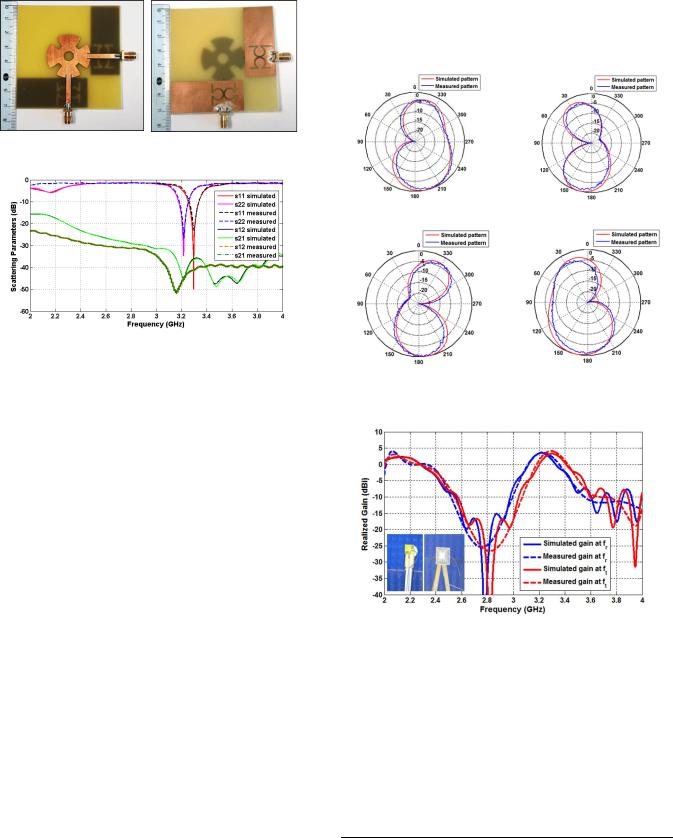
The fabricated prototype of the Tx/Rx antenna system is shown in Fig. 8. The scattering parameters of the system are measured using the Rohde & Schwarz ZVL20 Network Analyzer as shown in Fig. 9. The measured resonant
frequencies at transmitting and receiving ports are = 3.3 GHz and = 3.222 GHz, respectively. The measured
isolation between the two input ports are below −42 dB and
−46 dB at and , respectively which are higher than the simulated values of −36 dB and −45 dB, respectively. A good
1536-1225 (c) 2019 IEEE. Personal use is permitted, but republication/redistribution requires IEEE permission. See http://www.ieee.org/publications_standards/publications/rights/index.html for more information.
This article has been accepted for publication in a future issue of this journal, but has not been fully edited. Content may change prior to final publication. Citation information: DOI 10.1109/LAWP.2019.2937769, IEEE Antennas and Wireless Propagation Letters
AWPL-07-19-1368 |
4 |
agreement between the simulated and measured results are observed. However, there is a small difference between the simulated and measured results due to fabrication tolerance values.
(a) (b)
Fig. 8. Photograph of the fabricated prototype (a) front view, (b) back view.
Fig. 9. Comparison between the simulated and measured scattering parameters of the proposed TX/RX antenna system.
The radiation pattern and gain measurements are performed at the electronics research institute, Cairo, Egypt with the reference gain horn antenna of part number (P/N:JXTXLB-SJ- 20180) from A-INFOMW company. Fig. 10 shows the simulated and measured normalized radiation patterns in the E-
plane ( = 0° − ) |
and the H-plane ( = |
|
90° − ) at |
= 3.3 GHz and = 3.215 GHz. At |
|
|
|
|
= 3.3 GHz, the main |
lobe magnitudes are 4.27 dBi and |
|
|
|
|
4.37 dBi in E-plane and H-plane, respectively. While at = |
|||
|
|
|
|
3.215 GHz, |
the main |
lobe |
magnitudes are 4.36 dBi and |
4.46 dBi in |
E-plane |
and |
H-plane, respectively. Good |
agreements between the simulated and measured results are observed. Fig. 11 shows the simulated and measured gains for the proposed Tx/Rx antenna system versus frequency. The simulated efficiency is about 73% at = 3.3 GHz and 75% at
= 3.215 GHz.
V. COMPARISON WITH RELATED WORK
In this section, a comparison between the proposed full duplex Tx/Rx patch antenna and the state of the art works is summarized in Table V. The proposed antenna exhibits the smallest transmitting and receiving frequency space ratio= 0.0245 and the highest port to port isolation which exceeds −36 dB. Furthermore, it exhibits self-diplexing mechanism and bidirectional radiation pattern with high gain.
VI. CONCLUSION
A compact full duplex Tx/Rx patch antenna using a gear shaped radiating patch antenna and two omega-shaped DGSs is introduced. The use of omega-shaped DGS beneath the feeding
transmission lines of the patch constitute two high selectivity BPFs which can be tuned at any resonance frequencies by scaling the sizes of the DGSs by a specific scaling factor . Compared to the state of the art researches, the proposed design exhibited the highest isolation less than −36dB. Furthermore, it achieved the smallest frequency space ratio = 0.0245. Also, the compactness of the proposed antenna makes it attractive for practical applications.
(a) |
(b) |
(c) (d)
Fig. 10. Polar plots of E-Plane and H-Plane patterns of the proposed design
(a) |
= 3.3 GHz = 0°, |
(b) = 3.3 GHz = 90°, |
(c) = |
|
|
|
|
3.215 GHz = 0°, and (d) |
= 3.215 GHz = 90°. |
|
|
|
|
|
|
Fig. 11. Comparison between the measured and simulated gains of the Tx/Rx antenna system.
TABLE V
COMPARISON WITH RELATED WORK
Ref |
Frequency |
Isolation (dB) |
Size in (mm ) and w.r.t 0 |
||
|
space ratio |
|
|
|
|
[3] |
0.23 |
−30 |
(95 |
× 60 × 0.8) mm3 |
|
|
|
|
(0.98 × 0.75 × 0.09) 0 |
||
[4] |
0.22 |
−22 |
(51 × 18.8 × |
0.787) mm3 |
|
|
|
|
(0.66 × 0.66 |
× 0.021) 0 |
|
[5] |
0.74 |
−20 |
(70 |
× 70 × 1.7) mm3 |
|
|
|
|
(1.01 × 2.19 |
× 0.026) 0 |
|
[7] |
0.77 |
−26 |
(70 |
× 70 × 1.75) mm3 |
|
|
|
|
(0.9 |
× 0.9 × 0.022) 0 |
|
This |
0.0245 |
< −36 |
(70 |
× 70 × 1.6) mm3 |
|
work |
|
|
(0.56 × 0.56 × 0.0017) λ0 |
||
where λ0 is the free space wavelength at the lower edge frequency.
1536-1225 (c) 2019 IEEE. Personal use is permitted, but republication/redistribution requires IEEE permission. See http://www.ieee.org/publications_standards/publications/rights/index.html for more information.
This article has been accepted for publication in a future issue of this journal, but has not been fully edited. Content may change prior to final publication. Citation information: DOI 10.1109/LAWP.2019.2937769, IEEE Antennas and Wireless Propagation Letters
AWPL-07-19-1368 |
5 |
REFERENCES
[1]D. M. Pozar, “Microwave Engineering,” 2nd ed., New York, NY, USA: Wiley, 1998.
[2]J. S. Hong and M. J. Lancaster, “Microstrip filters for RF/Microwave applications,” John Wiley & Sons, Inc., New York, 2001.
[3]J. L. Xian, M. X. Ze, and S. Z. Pei, “Small Transmit-Receive Frequency Space Filtering Duplex Patch Antenna Array with High Isolation”,
Progress In Electromagnetics Research C, vol. 71, pp. 161–168, 2017.
[4]S. Mukherjee and A. Biswas, “Design of self-diplexing substrate integrated
waveguide cavity backed slot antenna,” IEEE Antennas and Wireless
Propagation Letters, vol. 15, pp. 1775–1778, 2016.
[5]Y. Lee, J. Tarng and S. Chung, “A filtering diplexing antenna for dual-band operation with similar radiation patterns and low cross-polarization levels”, IEEE Antennas and Wireless Propagation Letters, vol. 16, pp. 5861, 2017.
[6]A. A. Heidari, M. Heyrani, and M. Nakhkash, “A dual-band circularly polarized stub loaded microstrip patch antenna for GPS applications”,
Progress In Electromagnetics Research, PIER, vol. 92, pp. 195–208, 2009.
[7]Y. C. Lu, and Y. C. Lin, “A mode-based design method for dual-band and self-diplexing antennas using double T-stubs loaded aperture,” IEEE Antennas and Wireless Propagation Letters, vol. 60, pp. 5596–5603, 2012.
1536-1225 (c) 2019 IEEE. Personal use is permitted, but republication/redistribution requires IEEE permission. See http://www.ieee.org/publications_standards/publications/rights/index.html for more information.