

диафрагмированные волноводные фильтры / c356aa04-6fce-4cf3-8e18-099e753946c0
.pdfJournal of Computational Electronics https://doi.org/10.1007/s10825-020-01587-2
Design and implementation of miniaturized wideband microstrip patch antenna for high speed terahertz applications
S. M. Shamim1 · Muhammad Shahin Uddin1 · Md. Rabiul Hasan2 · Mousume Samad3
Received: 24 June 2020 / Accepted: 5 September 2020
© Springer Science+Business Media, LLC, part of Springer Nature 2020
Abstract
In the twenty-first century, graphene is widely used in wireless communication, especially in terahertz applications because of its amazing electrical, mechanical, and optical properties. This paper presents a graphene-based microstrip patch antenna at 0.72 THz resonant frequency for wireless communication. The proposed antenna shows 37.50% impedance bandwidth ranging from 0.53 to 0.84 THz at the center frequency of 0.72 THz. The result is demonstrated in terms of return loss (s11 < − 10 dB), voltage standing wave ratio (VSWR), input impedance, E-plane, and H-plane radiation pattern. The designing and simulation are performed using a full-wave electromagnetic simulator CST microwave studio based on the finite di erence time domain method. The simulation output shows a minimal return loss − 59.97 dB, VSWR 1.007, and good radiation pattern at 0.72 THz resonant frequency, which would be an excellent candidate for future wireless communication as well as medical imaging, homeland defense system, explosive detection, and material characterization application.
Keywords Microstrip antenna · Graphene · Impedance bandwidth · VSWR · Wireless communication
1 Introduction
The next-generation wireless communication requires highspeed data transmission facility among the di erent electrical devices. The demand of high-speed data transmission is increasing day by day and will reach the wired capacity limit very soon [1]. A special frequency band ranging from 0.1 to 10 THz termed as terahertz (THz) frequency band may be one of the possible solutions for high-speed data communication. Terahertz frequency band has already received
*\ S. M. Shamim
\ictshamim@yahoo.com
\Muhammad Shahin Uddin
\shahin.mbstu@gmail.com
\Md. Rabiul Hasan
\mdrabiul.hasan@wsu.edu
\Mousume Samad
\miti_ete_ruet@yahoo.com
1\ Mawlana Bhashani Science and Technology University,
Tangail 1902, Bangladesh
2\ Washington State University, Vancouver, WA, USA
3\ Bangladesh Army University of Engineering
and Technology, Natore 6431, Bangladesh
considerable attention due to larger bandwidth, high data rate, non-ionizing, and high resolution in wireless communication [2]. Its spectral band lies between the microwave and mid-infrared ranges that support more extensive bandwidth ranges up to hundreds of GHz. In the near-future high channel capacity, higher data rates, and high-resolution broadcast facilities are possible with the THz frequency band [3]. This frequency band has explored potential applications in medical imaging, agriculture field, spectroscopy, astronomy, biosensing, radar, explosive detection, material analysis, airport security screening, etc. [4, 5].
An antenna that transmits or receive electromagnetic wave in free space plays an important role in wireless communication. The performance of the terahertz system directly depends on the performance of the antenna [5]. The microstrip patch antenna is widely used for its lightweight, lower-cost, smaller-size, and low-profile design method on printed circuit board (PCB) [6, 7]. Most of the radio frequency antenna or microwave antenna is radiated using copper conductor. The implementation of copper as a conductor in terahertz frequency is di cult for this low conductivity and lower mobility [8].
In addition, the invention of graphene material is a breakthrough in the THz device and wireless communications. Recently, graphene has attracted extreme attention in several
1 3
\ |
Journal of Computational Electronics |
|
|
educational and industrial researches in the THz regime [9]. The graphene-enabled filters [10, 11], modulators [12, 13], resonators [14, 15], absorbers [16, 17], waveguides [18, 19], and phase shifters [20] are the most popular applications in wireless communication. Moreover, the graphene-based antenna provides interesting applications in the terahertz regime [21–26]. At room temperature, graphene possesses very high carrier mobility around 8000–10,000 cm2 V−1 s−1, which can reach up to 200,000 cm2 V−1 s−1. Graphene surface electrical conductivity can be determined using the Kubos formula [27, 28].
|
|
|
|
2 + |
∕R |
|
|
|
|
|
|
|
|
|
|
|||||||||
|
|
|
2IE2K |
B |
T |
|
|
|
|
|
|
|
|
C |
|
|
||||||||
S( ) = 2 |
|
|
|
I |
|
|
LN |
|
2 COSH |
2KBT |
|
|
||||||||||||
+ |
|
|
|
|
|
|
|
|
|
|
|
|
|
B |
|
|
|
|
|
|||||
|
E |
|
1 |
+ |
1 |
TAN−1 |
|
|
− |
2 C |
|
|
||||||||||||
|
|
|
|
|
|
|
|
|
|
|
|
|
|
|
|
|
||||||||
|
|
4 |
|
|
2 |
|
|
|
|
|
|
2K |
T |
|
|
|||||||||
|
|
|
|
|
|
|
|
|
|
|
|
C |
|
|
|
2 |
B |
|
|
|
|
|
||
− |
I |
|
|
LN |
|
|
|
|
|
|
|
+ 2 C |
|
|
|
|
|
|
||||||
2 |
|
|
|
|
|
|
|
|
2 |
|
|
|
|
2 |
|
(1) |
||||||||
|
|
|
|
|
|
|
|
|
|
|
|
|||||||||||||
|
|
|
|
|
|
|
|
− 2 |
|
|
+ 4 K |
|
T |
|
|
|
||||||||
|
|
|
|
|
|
|
|
|
|
|
|
|
|
|
|
|||||||||
Graphene total electrical conductivity is the summation of intra-band and inter-band conductivity, which can be simplified using the following ways [29].
INTRA ( ) = |
|
|
2E2KBTI |
|
|
|
LN |
2 COSH |
C |
|
|
|
(2) |
|||||||||
2 + I −1 |
|
|
2KBT |
|
|
|||||||||||||||||
|
|
|
|
|
|
|
|
|
|
|
|
|
|
∞ H( ) − H |
|
|
|
|
|
|||
|
|
|
|
|
E |
2 |
|
|
|
|
4 |
|
|
|
||||||||
|
|
|
|
|
|
|
|
|
|
|
|
|
|
|
|
|
||||||
|
|
( |
|
) = |
|
H |
|
+ |
I |
|
|
2 |
|
|
|
(3) |
||||||
INTER |
4 |
2 |
|
|
|
|
|
|
|
|||||||||||||
|
|
|
|
|
|
0 2 − 4 2 |
|
|||||||||||||||
|
|
|
|
|
|
|
|
|
|
|
|
|
|
|
|
|
|
|
|
|
|
|
|
|
|
|
|
|
|
|
|
|
|
|
|
|
|
|
|
|
|
|
|
|
|
|
|
|
|
|
|
|
|
|
|
|
|
|
|
|
|
|
|
|
|
|
|
|
where KB is Boltzmann’s constant, τ relaxation time, h reduces plank constant, T temperature, ω angular frequency, and μc chemical potential. The graphene-based antenna is di erent from the conventional antenna for their unique electromagnetic formation procedure [30]. Recently, researchers prefer graphene as a conductive material for low energy consumption, low channel electrical resistance, linear energy dispersion, linear current–voltage characteristics, high charges motilities, and Fermi velocity. It is also compatible with high-frequency operation [31]. The conductivity of graphene changes from microwave frequencies to THz for frequency-dependent behavior [32]. The comprehensive characterization of graphene material has been chosen for implementing the proposed antenna for their dramatic electrical, physical, mechanical, and optical properties. The default material property of CST microwave studio software has been used in the designed antenna.
Recently, several studies have performed in antenna designing in THz regime for di erent applications in wireless
communication. A wideband graphene-based antenna has been presented by Nickpay et al. [33] using silicon dioxide (SiO2) substrate at 1.06 THz resonant frequency. The proposed antenna has an impedance bandwidth of 26% with return loss (−24 dB) at 1.06 THz center frequency. A comparative study on rectangular microstrip patch antenna using RT/Duriod 6006 substrate has been investigated by Younssi et al. [34]. This antenna has larger in size 1000×1000×200 µm3 which exhibits impedance bandwidth of 22.47%. The photonic bandgap structure-based patch antenna has been implemented by Nejati et al. [35] on the Pyrex substrate. This antenna also has a larger dimension 500×500×10 µm3 with impedance bandwidth of 33%. Sirmaci et al. [36] has reported fishnet-based metamaterial loaded patch antenna for terahertz application using a Quartz substrate. The bandwidth of −10 dB has been found 8.2% in their proposed antenna. A rectangular microstrip patch antenna with a smaller impedance bandwidth of 5.85% using a polyimide substrate has been implemented by Dhillon et al. [37] for video rate imaging and defense application. A novel microstrip patch antenna has been designed and analyzed using a polyimide substrate at 0.63 THz center frequency with 5.75% impedance bandwidth has been presented by Kushwaha et al. [38].
In addition, di erent researchers have been designed different antenna in THz frequency bands for various applications. Their proposed antenna either larger in size or su er from narrow bandwidth. Consequently, further studies are required to support high-speed data transmission at the THz spectrum in wireless communication. In this research, an e ective rectangular microstrip patch antenna has been proposed and presented for medical imaging, homeland defense system, explosive detection, material characterization, etc. The antenna has a wide impedance bandwidth of 37.50% ranging from 0.53 to 0.84 THz at center frequency 0.72 THz. Moreover, the performance of the proposed antenna has been demonstrated in terms of return loss, VSWR, directivity, input impedance, E-plane, and H-plane radiation pattern.
2 Antenna design and confguration
The microstrip patch antenna has a low cost, low profile, ease of fabrication, and capability of integration with electronics device. A good understanding of various antenna parameters is required to design a high-performance antenna. These parameters include radiating patch, feeding technique, dielectric material with appropriate thickness, dielectric constant, and loss tangent. The substrate material is placed between the ground plane and radiating patch with the same length and width as that of the ground plane.
The proposed antenna is designed on Arlon 1000 substrate with relative permittivity of 10.2 and loss tangent of 0.0023 the substrate. The substrate materials thickness is
1 3

Journal of Computational Electronics\
designed 45 µm, length 120 µm, and width. The permittivity or dielectric constant (εr) of the substrate material has a direct e ect upon the antenna size and performance. A rectangular radiating patch shape, i.e., 60 µm and 70 µm with the microstrip feed line, has been implanted over 120 µm. The ground plane and radiating path of the antenna are designed using high conductivity copper and graphene materials, respectively. The overall dimension of the proposed antenna is 120 × 120 × 45 µm3, which is depicted in Fig. 1. Di erent feeding techniques, i.e., microstrip line, aperture coupling, coaxial coupling, and proximity coupling, are available to feed the antenna. The microstrip edge line feeding technique has been used in the proposed antenna for a simple fabrication procedure and good impedance matching with the input signal. A waveguide port excitation source has been chosen for the proposed antenna microstrip antenna. The geometric parameters of the antenna are tabulated in Table 1.
3 Result and discussion
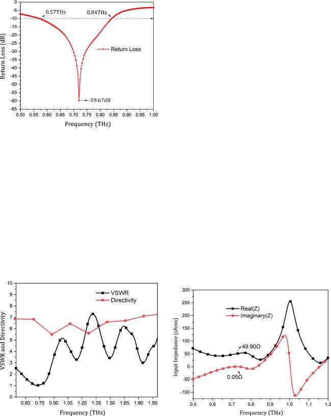
The antenna has been simulated using EM simulation software CST microwave studio. The radiation characteristics of the proposed antenna are designed and investigated in terms of return loss, VSWR, input impedance, directivity, E-plane, and H-plane radiation pattern. Refection coe cient or return loss of an antenna is the ratio of incident power to refected power, which is measured in decibels (dB). It is represented by s11 (dB), which should be less than − 10 dB for an e ective antenna. Figure 2 depicts the simulated return loss plot of the proposed antenna.
Fig. 1 The perspective view of the proposed microstrip antenna
Table 1 Geometric parameters of the graphene-based antenna for a center frequency of 0.72 THz
Parameter |
Dimen- |
|
sions |
|
(μm) |
Length of the patch (Lp) |
60 |
Width of the patch (Wp) |
70 |
Length of the substrate (Ls) |
120 |
Width of the substrate(Ws) |
120 |
Length of the ground (Lg) |
120 |
Width of the ground (Wg) |
120 |
Height of the substrate (Hs) |
45 |
Microstrip feed width (Wf) |
14 |
The projected design antenna has a return loss of − 59.67 dB and bandwidth 280.58 GHz at center frequency 0.72 THz. The antenna has a wide impedance bandwidth of 37.50% ranging from 0.57 to 0.84 THz. The impedance matching between the transmission line and antenna is a key factor for evaluating antenna performance. The voltage standing wave ratio (VSWR) defines how much signal is refected back to the source due to a mismatch between source impedance and antenna impedance. Figure 3 depicts the VSWR and directivity plot for the proposed antenna.
VSWR values always prefer less than 2 for good impedance matching [39, 40]. The refected signal causes the standing wave voltage to be present in the feed line, which deteriorates the performance of the antenna. The suggested antenna VSWR has a value of 1.002 at operating frequency 0.72 THz. Ideally, the value of VSWR should be equal to 1 means 100% power is accepted, and zero refection [41]. Directivity is another crucial parameter to evaluate antenna
1 3
\ |
Journal of Computational Electronics |
|
|
Fig. 2 The return loss characteristics of the proposed antenna
performance that defines the directionality of the antenna. The proposed antenna is directional at respective resonant frequency 0.72 THz with directivity 6.60 dB, which is identified in Fig. 3 using a circled red sloid line. Input impedance versus frequency plot is another important characteristic for evaluating antenna performance. Figure 4 depicts the input impedance characteristic of the proposed antenna, which defines impedance matching between the input signal and feed line. The input impedance of the proposed antenna is 49.90 Ω in the real part and 0.050 Ω in the imaginary part at resonating frequency 0.72 THz. The value of input
Fig. 3 The VSWR characteristics of the proposed antenna (Color figure online)
impedance should be 50 Ω in real and 0 Ω in imaginary for properly match between the input signal and feed line [41].
The co-polar and cross-polar radiation pattern in both E-plane (ϕ = 0°) and H-plane (ϕ = 90°) of the proposed antenna is shown in Fig. 5. The orientation of the antenna such that bore-sight direction toward the vertical direction by varying theta (θ) from 0° to 360° for a fixed value of phi (ϕ) [42]. The main lobe magnitude is around 4.4 dBi, main lobe direction is 0°, and angular width (3 dB) 146.4° has been obtained for E-plane. For the H-plane, the main lobe magnitude, main lobe direction, sidelobe level, and angular width (3 dB) are 5.9 dBi, 30°, − 8.9 dB, and 79.4°, respectively, obtained at resonant frequency 0.72 THz.
The proposed structure has been compared with previously reported terahertz antenna structure, which is tabulated in Table 2. The parameter considered for this comparison is the antenna dimension, return loss, percentage bandwidth, and substrate material.
It can be concluded that the proposed antenna has a wider impedance bandwidth than the existing antenna. Though Nickpay et al. [33] antenna has smaller in size, and Dhillon et al. [37] have minimal return loss, they have narrow bandwidth compare to the proposed antenna. The impedance bandwidth of the proposed antenna is 37.50% at 0.72 THz resonant frequency, which is comparatively higher than the previous works. This large bandwidth in the terahertz regime makes it a good candidate for future high-speed wireless communication. After comparing the existing terahertz antenna models, the proposed antenna has good performance characteristics, small size, and very impedance bandwidth.
Fig. 4 The input impedance characteristics of the proposed antenna
1 3

Journal of Computational Electronics\
Fig. 5 The radiation pattern of the proposed antenna a E-plane, b H-plane
Table 2 Comparison study with existing works
References |
Antenna size (µm3) |
Resonant frequency |
Return loss (dB) |
Bandwidth (%) |
Substrate material |
|
|
(THz) |
|
|
|
|
|
|
|
|
|
[33] |
93 × 120 × 25 |
1.06 |
− 24 |
26 |
SiO2 |
[34] |
1000 × 1000 × 200 |
0.692 |
− 41.65 |
22.47 |
RT/Duriod 6006 |
[35] |
500 × 500 × 10 |
0.67 |
− 24 |
33 |
Pyrex |
[36] |
180 × 212 × 10 |
1.08 |
− 57 |
8.2 |
Quartz |
[37] |
208.90 × 422 × 20 |
0.67 |
− 81.18 |
5.85 |
Polyimide |
[38] |
800 × 600 × 191.29 |
0.63 |
− 44.71 |
5.75 |
Polyimide |
Proposed works |
120 × 120 × 45 |
0.72 |
− 59.67 |
37.91 |
Arlon AD 1000 |
|
|
|
|
|
|
4 Conclusion
A compact, low-cost, and low-profile graphene-based microstrip patch antenna is investigated in this research. The result demonstrates that the designed antenna can operate from 0.53 to 0.84 THz at center frequency 0.72 THz, having 37.50% impedance bandwidth. The maximum return loss − 59.87 dB has been achieved with a good radiation pattern at 0.72 THz resonant frequency. The maximum directivity 6.60 dB, VSWR 1.007 is also obtained at 0.72 THz frequency. The proposed antenna can be used in various applications such as medical imaging, tumor and cancerous cell detection, explosive detection, chemical detection, and homeland defense system.
Funding No funding was received.
Compliance with ethical standards
Conflict of interest The authors declare no confict of interest.
References
\1.\ Khan, M.A.K., Shaem, T.A., Alim, M.A.: Analysis of graphene based miniaturized terahertz patch antennas for single band and dual band operation. Optik 194, 163012 (2019)
\2.\ Son, J.H.: Terahertz electromagnetic interactions with biological matter and their applications. J. Appl. Phys. 105(10), 102033 (2009)
1 3
\ |
Journal of Computational Electronics |
|
|
\3.\ Akyildiz, I.F., Jornet, J.M., Han, C.: Terahertz band: next frontier for wireless communications. Phys. Commun. 12, 16–32 (2014)
\4.\ Kushwaha, R.K., Karuppanan, P.: Enhanced radiation characteristics of graphene-based patch antenna array employing photonic crystals and dielectric grating for THz applications. Optik 200, 163422 (2020)
\5.\ Sun, P.L.: 420-GHz terahertz SIW slot antenna with quartz superstrates in silicon technology. Optoelectron. Lett. 16(1), 25–28 (2020)
\6.\ Ghosh, S., Das, S., Samantaray, D., Bhattacharyya, S.: Mean- der-line-based defected ground microstrip antenna slotted with split-ring resonator for terahertz range. Eng. Rep. 2(1), e12088 (2020)
\7.\ Divya, C., Koushick, V.: Design and implementation of slotted metamaterial stacked microstrip patch antenna for broadband applications. J. Phys: Conf. Ser. 1432(1), 012067 (2020)
\8.\ Shalini, M.: Performance predictions of slotted graphene patch antenna for multi-band operation in terahertz regime. Optik 204, 164223 (2020)
\9.\ Kushwaha, R.K., Karuppanan, P.: Parasitic-coupled high-gain
graphene antenna employed on PBG dielectric grating substrate for THz applications. Microw. Opt. Technol. Lett. 62(1), 439– 447 (2020)
\10.\ Khani, S., Danaie, M., Rezaei, P.: Miniaturized microstrip dualband bandpass filter with wide upper stop-band bandwidth. Analog Integr. Circuits Signal Process. 98(2), 367–376 (2019)
11\ .\ Kiani, N., Afsahi, M.: Design and fabrication of a compact SIW diplexer in C-band. Iran. J. Electr. Electron. Eng. 15(2), 189–194 (2019)
\12.\ Yang, Z., Lu, R., Wang, Y., Cai, S., Zhang, Y., Wang, X., Liu, Y.: A fabrication-friendly graphene-based polarization insensitive optical modulator. Optik 182, 1093–1098 (2019)
13\ .\ Chashmi, M.J., Rezaei, P., Kiani, N.: Y-shaped graphene-based antenna with switchable circular polarization. Optik 200, 163321 (2020)
\14.\ Khani, S., Danaie, M., Rezaei, P.: Realization of single-mode plasmonic bandpass filters using improved nanodisk resonators. Opt. Commun. 420, 147–156 (2018)
15\ .\ Javanshir, S., Pourziad, A., Nikmehr, S.: Optical temperature sensor with micro ring resonator and graphene to reach high sensitivity. Optik 180, 442–446 (2019)
\16.\ Biabanifard, M., Asgari, S., Biabanifard, S., Abrishamian, M.S.: Analytical design of tunable multi-band terahertz absorber composed of graphene disks. Optik 182, 433–442 (2019)
17\ .\ Vahedian, M., Naser-Moghadasi, M.: Surface distortion compensation in nano particle by using the graphene layer to obtain reconfigurable absorber. Optik 160, 259–266 (2018)
\18.\ Toqeer, I., Gha ar, A., Naz, M.Y., Sultana, B.: Characteristics of dispersion modes supported by graphene chiral graphene waveguide. Optik 186, 28–33 (2019)
19\ .\ Wu, W., Zhang, J., Li, Y., Chen, W., Wang, P., Li, S., Ding, J., Zhang, B., Lu, H., Li, J., Fu, Q.: Numerical investigation of an electro-optic majority voting circuit utilizing graphene–silicon nitride waveguides. Optik 186, 205–211 (2019)
\20.\ AzimBeik, M., Moradi, G., Shirazi, R.S.: Graphene-based switched line phase shifter in THz band. Optik 172, 431–436 (2018)
21\ .\ Efazat, S.S., Basiri, R., Makki, S.V.A.D.: The gain enhancement of a graphene loaded reconfigurable antenna with non-uniform metasurface in terahertz band. Optik 183, 1179–1190 (2019)
\22.\ Anand, S., Kumar, D.S., Wu, R.J., Chavali, M.: Graphene nanoribbon based terahertz antenna on polyimide substrate. Optik 125(19), 5546–5549 (2014)
\23.\ Samanta, G., Mitra, D.: Wideband THz antenna using graphene based tunable circular reactive impedance substrate. Optik 158, 1080–1087 (2018)
\24.\ Bazgir, M., Naser-Moghadasi, M., Zarrabi, F.B., Arezomand, A.S., Heydari, S.: Nano particle implementation in nano loop antenna for energy harvesting application and light trapping. Optik 132, 127–133 (2017)
25\ .\ Bansal, G., Singh, A., Bala, R.: A triband slotted bow-tie wideband THz antenna design using graphene for wireless applications. Optik 185, 1163–1171 (2019)
\26.\ Kazemi, A.H., Mahani, F.F., Mokhtari, A.: Peak amplitude enhancement of photoconductive antenna using periodic nanoslit and graphene in the THz band. Optik 185, 114–120 (2019)
27\ .\ Chashmi, M.J., Rezaei, P., Kiani, N.: Polarization controlling of multi resonant graphene-based microstrip antenna. Plasmonics 15(2), 417–426 (2020)
\28.\ Hanson, G.W.: Dyadic Green’s functions and guided surface waves for a surface conductivity model of graphene. J. Appl. Phys. 103(6), 064302 (2008)
29\ .\ Hanson, G.W.: Dyadic Green’s functions for an anisotropic, non-local model of biased graphene. IEEE Trans. Antennas Propag. 56(3), 747–757 (2008)
\30.\ Bala, R., Singh, R., Marwaha, A., Marwaha, S.: Wearable graphene based curved patch antenna for medical telemetry applications. Appl. Comput. Electromagn. Soc. J. 31(5), 543–550 (2016)
31\ .\ Meyer, J.C., Geim, A.K., Katsnelson, M.I., Novoselov, K.S., Booth, T.J., Roth, S.: The structure of suspended graphene sheets. Nature 446(7131), 60–63 (2007)
\32.\ Bala, R., Marwaha, A., Marwaha, S.: Mathematical formulation of surface conductivity for graphene material. J. Eng. Sci. Technol. 12(6), 1677–1684 (2017)
33\ .\ Nickpay, M.R., Danaie, M., Shahzadi, A.: Wideband rectangular double-ring nanoribbon graphene-based antenna for terahertz communications. IETE J. Res. (2019). https://doi. org/10.1080/03772063.2019.1661801
\34.\ Younssi, M., Jaoujal, A., Yaccoub, M.D., El Moussaoui, A., Aknin, N.: Study of a microstrip antenna with and without superstrate for terahertz frequency. Int. J. Innov. Appl. Stud. 2(4), 369–371 (2013)
35\ .\ Nejati, A., Sadeghzadeh, R.A., Geran, F.: E ect of photonic crystal and frequency selective surface implementation on gain enhancement in the microstrip patch antenna at terahertz frequency. Phys. B 449, 113–120 (2014)
\36.\ Sirmaci, Y.D., Akin, C.K., Sabah, C.: Fishnet based metamaterial loaded THz patch antenna. Opt. Quantum Electron. 48(2), 168 (2016)
37\ .\ Dhillon, A.S., Mittal, D., Sidhu, E.: THz rectangular microstrip patch antenna employing polyimide substrate for video rate imaging and homeland defence applications. Optik 144, 634–641 (2017)
\38.\ Kushwaha, R.K., Karuppanan, P., Malviya, L.D.: Design and analysis of novel microstrip patch antenna on photonic crystal in THz. Phys. B 545, 107–112 (2018)
39\ .\ Khattak, M.I., Sohail, A., Khan, U., Barki, Z., Witjaksono, G.: Elliptical slot circular patch antenna array with dual band behaviour for future 5G mobile communication networks. Prog. Electromagn. Res. 89, 133–147 (2019)
\40.\ Kaur, G., Mehta, V., Sidhu, E.: Rectangular terahertz microstrip patch antenna design for vitamin K2 detection applications. In: 2017 1st International Conference on Electronics, Materials Engineering and Nano-Technology (IEMENTech), pp. 1–3. IEEE (2017)
1 3

Journal of Computational Electronics\
41\ .\ Singh, A., Singh, S.: A trapezoidal microstrip patch antenna on photonic crystal substrate for high speed THz applications. Photonics Nanostruct. Fundam. Appl. 14, 52–62 (2015)
\42.\ Balanis, C.A.: Antenna Theory Analysis and Design, 2nd edn. Wiley, New York (1997)
Publisher’s Note Springer Nature remains neutral with regard to jurisdictional claims in published maps and institutional a liations.
1 3