

диафрагмированные волноводные фильтры / d34f7ab5-e1c5-4301-b1a1-d345b1634b37
.pdfRadio Science
RESEARCH ARTICLE
10.1002/2016RS005999
Key Points:
•Design of manifold multiplexers using filters in all-inductive dual-mode waveguide technology
•Adapted a design technique for manifold multiplexers to the analysis of the proposed technology
•Presented two designs using E-plane and H-plane manifolds to prove
the e ectiveness of the proposed structure
Correspondence to:
A. Alvarez-Melcon, alejandro.alvarez@upct.es
Citation:
Pons Abenza, A., M. Martinez-Mendoza, F. D. Quesada Pereira, and
A. Alvarez-Melcon (2016), Design of manifold multiplexers in all-inductive dual-mode rectangular waveguide technology using the coupling matrix formalism, Radio Sci., 51, 1065–1080, doi:10.1002/2016RS005999.
Received 10 MAR 2016
Accepted 15 JUN 2016
Accepted article online 22 JUN 2016 Published online 19 JUL 2016
©2016. American Geophysical Union.
All Rights Reserved.
Design of manifold multiplexers in all-inductive dual-mode rectangular waveguide technology using the coupling matrix formalism
A. Pons Abenza1, M. Martinez-Mendoza2,3, F. D. Quesada Pereira1, and A. Alvarez-Melcon1
1Information and Communication Technologies, Technical University of Cartagena, Murcia, Spain,
2Ferdinand-Braun-Institut, Leibniz Institut für Höchstfrequenztechnik, Berlin, Germany, 3Now at Thales Alenia Space, Madrid, Spain
Abstract This paper presents for the first time the design of manifold multiplexers in waveguide technology using all-inductive dual-mode channel filters. It is shown that very complex transfer functions can be implemented for the channels, using simple structures that can be analyzed and manufactured with increased simplicity as compared to other commercial solutions. In this paper we adapt a standard design technique for manifold multiplexers to the new proposed technology. The paper is illustrated with the design of two triplexers, using H-type and E-type waveguide manifolds, with filters implementing two transmission zeros in the insertion loss response for maximum isolation between channels. Results show that the procedure is indeed e ective and can be used for the design of practical multiplexer configurations.
1. Introduction
Waveguide technology for the radiofrequency components of satellite systems is very popular, due to some advantages that this technology o ers, such as low losses and high power handling capability. Waveguide multiplexers are one of the most important components in the payloads of communication satellites [see, for instance, Newell and Bird, 1994]. They are commonly used in the input and output front ends to separate (input multiplexer, IMUX) or combine (output multiplexer, OMUX) a certain number of radio frequency channels. The IMUX and OMUX performance have a huge impact on the overall communication satellite system. The channelization of these components is usually achieved by using any of the classical multiplexer network implementations [Cameron et al., 2007].
One of the main problems with these components is related to the size of the multiplexer itself. Additionally, good reflection electrical response in the common port (common port return loss, CPRL) and good rejection levels between adjacent channels are required in order to achieve good performance, usually very desirable in space applications. The most suitable configuration to obtain all of these goals at the same time is the one known as the manifold configuration [Cameron et al., 2007]. On the contrary, a disadvantage of manifold multiplexers is that the whole device must be redesigned if the frequency plan of the channels is modified. This is because all channel filters present strong interactions through the manifold. This does not happen in other types of multiplexers, such as those based on circulators or coupled hybrids, where isolation between channels is typically very high [Cameron et al., 2007].
In this context, this paper presents a manifold multiplexer configuration using all-inductive dual-mode filters in rectangular waveguide technology [Guglielmi et al., 2001; Martinez Mendoza et al., 2015]. Although multiplexers in all-inductive technology have been previously proposed in Carceller et al. [2015], Garay et al. [2005], Shang et al. [2013], and Xia et al. [2014], this is the first time that dual-mode cavities combined with all-inductive technology are integrated in manifold multiplexers. In Carceller et al. [2015] and Garay et al. [2005], all-inductive multiplexers are designed using e cient techniques. However, no transmission zeros were included in the insertion loss response of the channel filters. Consequently, not very large isolation could be achieved between contiguous channels. Other all-inductive alternatives were reported in Shang et al. [2013] and Xia et al. [2014]. In those works transmission zeros could be implemented using cross couplings between nonadjacent resonators, by introducing folded structures and the concept of resonator junctions. With these folded topologies the number and positions of the transmission zeros are limited. This is mainly because the signs of the couplings are di cult to adjust with all-inductive irises. On the contrary, another advantage of the structures proposed in Shang et al. [2013] and Xia et al. [2014] is that they are very compact.
PONS ABENZA ET AL. |
MULTIPLEXER WITH ALL-INDUCTIVE FILTERS |
1065 |

10.1002/2016RS005999
|
|
|
|
|
|
|
|
|
|
|
|
|
|
|
|
|
|
|
|
|
|
|
|
|
|
|
This is because they avoid to have a man- |
|
|
|
|
|
|
|
|
|
|
|
|
|
|
|
|
|
|
|
|
|
|
|
|
|
|
|
ifold by introducing resonant junctions. |
|
|
|
|
|
|
|
|
|
|
|
|
|
|
|
|
|
|
|
|
|
|
|
|
|
|
|
|
|
|
|
|
|
|
|
|
|
|
|
|
|
|
|
|
|
|
|
|
|
|
|
|
|
|
|
It is known that multiplexers based on |
|
|
|
|
|
|
|
|
|
|
|
|
|
|
|
|
|
|
|
|
|
|
|
|
|
|
|
|
|
|
|
|
|
|
|
|
|
|
|
|
|
|
|
|
|
|
|
|
|
|
|
|
|
|
|
junctions are more compact than those |
|
|
|
|
|
|
|
|
|
|
|
|
|
|
|
|
|
|
|
|
|
|
|
|
|
|
|
based on manifold structures. However, |
|
|
|
|
|
|
|
|
|
|
|
|
|
|
|
|
|
|
|
|
|
|
|
|
|
|
|
the advantage of using manifold configu- |
|
|
|
|
|
|
|
|
|
|
|
|
|
|
|
|
|
|
|
|
|
|
|
|
|
|
|
|
|
|
|
|
|
|
|
|
|
|
|
|
|
|
|
|
|
|
|
|
|
|
|
|
|
|
|
|
|
|
|
|
|
|
|
|
|
|
|
|
|
|
|
|
|
|
|
|
|
|
|
|
|
|
|
rations is that additional channels can be |
|
|
|
|
|
|
|
|
|
|
|
|
|
|
|
|
|
|
|
|
|
|
|
|
|
|
|
accommodated more easily, without the |
|
|
|
|
|
|
|
|
|
|
|
|
|
|
|
|
|
|
|
|
|
|
|
|
|
|
|
|
|
|
|
|
|
|
|
|
|
|
|
|
|
|
|
|
|
|
|
|
|
|
|
|
|
|
|
need to start the design from scratch. |
|
|
|
|
|
|
|
|
|
|
|
|
|
|
|
|
|
|
|
|
|
|
|
|
|
|
|
|
|
|
|
|
|
|
|
|
|
|
|
|
|
|
|
|
|
|
|
|
|
|
|
|
|
|
|
With respect to those previously reported |
|
Figure 1. Equivalent circuit of the three-channel manifold multiplexer |
structures the proposed implementa- |
|||||||||||||||||||||||||
|
to be designed. |
tion in this paper introduces dual-mode |
|||||||||||||||||||||||||
|
|
|
|
|
|
|
|
|
|
|
|
|
|
|
|
|
|
|
|
|
|
|
|
|
|
|
cavities in all-inductive technology. This |
|
allows the implementation of transmission zeros at finite frequencies with cavities placed in in-line configura- |
||||||||||||||||||||||||||
|
tion and therefore eliminating the need to introduce folded topologies. Each dual-mode cavity is responsible |
||||||||||||||||||||||||||
|
for one transmission zero, and its position can be easily adjusted using the zero shifting property of transver- |
||||||||||||||||||||||||||
|
sal filter sections [Amari et al., 2004]. Also, the use of manifold configurations allows to incorporate any |
||||||||||||||||||||||||||
|
number of channels in the structure, without significantly increasing the complexity of the design process. |
||||||||||||||||||||||||||
|
In addition to multiplexers in all-inductive technology, other very popular alternatives include the use of |
||||||||||||||||||||||||||
|
dual-mode circular waveguides [Brumos et al., 2014]. The main advantage of this technology is that dual-mode |
||||||||||||||||||||||||||
|
circular resonators operating in the dominant TE11 mode exhibit very large quality factors. Consequently, |
||||||||||||||||||||||||||
|
lower insertion losses are to be expected. However, they lead to more complex structures, since usually |
||||||||||||||||||||||||||
|
cross-shaped irises and metallic inserts are needed to tune and to properly couple the degenerate resonant |
||||||||||||||||||||||||||
|
modes. The analysis of these structures requires full 3-D models, which usually leads to large computational |
||||||||||||||||||||||||||
|
resources. Also, full 3-D manufacturing techniques are required, which could increase the overall cost of the |
||||||||||||||||||||||||||
|
hardware. On the contrary, the analysis of the structures proposed in this work can be analyzed with 2-D |
||||||||||||||||||||||||||
|
models, which can be made computationally very e cient [Perez Soler et al., 2007]. Another advantage of the |
||||||||||||||||||||||||||
|
structure proposed is that it is simpler to manufacture, so it may lead to cost reduction as compared to full |
||||||||||||||||||||||||||
|
3-D waveguide structures. |
|
|||||||||||||||||||||||||
|
In the above context, a three-channels manifold multiplexer with all-inductive dual-mode rectangular waveg- |
||||||||||||||||||||||||||
|
uide filters is presented for the first time. A general equivalent circuit of the triplexer to be designed can be |
||||||||||||||||||||||||||
|
seen in Figure 1. Multiplexer design techniques for the manifold configuration are reviewed, for instance, |
||||||||||||||||||||||||||
|
in Cameron and Yu [2007]. They are known to be very e ective for the design of narrowband multiplexers, |
||||||||||||||||||||||||||
|
as those considered in the present work. In wideband multiplexers, however, the interactions between |
||||||||||||||||||||||||||
|
the channel filters through the manifold are di cult to compensate using only transmission line sections. |
||||||||||||||||||||||||||
|
Consequently, more elaborated techniques, as introduced in Carceller et al. [2015], may be needed. |
||||||||||||||||||||||||||
|
In this work, the design techniques proposed in Cameron et al. [2007] and Cameron and Yu [2007] are used |
||||||||||||||||||||||||||
|
for the design of narrowband multiplexers. We have verified that this technique was useful for the design of |
||||||||||||||||||||||||||
|
multiplexers with global fractional bandwidths of up to 12%. |
|
|||||||||||||||||||||||||
|
Iterative user-controlled optimization follows the procedure described in Cameron et al. [2007] and Cameron |
||||||||||||||||||||||||||
|
and Yu [2007]. In this paper we adapt the general procedure to the design of a triplexer using the channel |
||||||||||||||||||||||||||
|
filters with the coupling topology shown in Figure 2. It can be seen that it corresponds to a sixth-order filter, |
||||||||||||||||||||||||||
|
|
|
|
|
|
|
|
|
|
|
|
|
|
|
|
|
|
|
|
|
|
|
|
|
|
|
that can implement two transmission zeros. |
|
|
|
|
|
|
|
|
|
|
|
|
|
|
|
|
|
|
|
|
|
|
|
|
|
|
|
To increase isolation between the channels, |
|
|
|
|
|
|
|
|
|
|
|
|
|
|
|
|
|
|
|
|
|
|
|
|
|
|
|
the two transmission zeros will be located |
|
|
|
|
|
|
|
|
|
|
|
|
|
|
|
|
|
|
|
|
|
|
|
|
|
|
|
|
|
|
|
|
|
|
|
|
|
|
|
|
|
|
|
|
|
|
|
|
|
|
|
|
|
|
|
in the frequency axis, at both sides of the |
|
|
|
|
|
|
|
|
|
|
|
|
|
|
|
|
|
|
|
|
|
|
|
|
|
|
|
passband. For the individual filter design pro- |
|
|
|
|
|
|
|
|
|
|
|
|
|
|
|
|
|
|
|
|
|
|
|
|
|
|
|
cess, coupling matrix techniques are applied |
|
|
|
|
|
|
|
|
|
|
|
|
|
|
|
|
|
|
|
|
|
|
|
|
|
|
|
|
|
|
|
|
|
|
|
|
|
|
|
|
|
|
|
|
|
|
|
|
|
|
|
|
|
|
|
to obtain a suitable frequency response for |
|
|
|
|
|
|
|
|
|
|
|
|
|
|
|
|
|
|
|
|
|
|
|
|
|
|
|
each channel. Equivalent circuit models for |
|
|
|
|
|
|
|
|
|
|
|
|
|
|
|
|
|
|
|
|
|
|
|
|
|
|
|
the filter topology are then built by using |
|
|
|
|
|
|
|
|
|
|
|
|
|
|
|
|
|
|
|
|
|
|
|
|
|
|
|
the general coupling matrix circuit theory |
|
Figure 2. Coupling topology for the channel filters of the triplexer. |
[Cameron et al., 2007]. |
|||||||||||||||||||||||||
|
|
|
|
|
|
|
|
||||||||||||||||||||
PONS ABENZA ET AL. |
|
|
|
|
|
MULTIPLEXER WITH ALL-INDUCTIVE FILTERS |
1066 |
||||||||||||||||||||

Radio Science |
10.1002/2016RS005999 |
|
|
Figure 3. Physical structure in all-inductive dual-mode waveguide technology implementing the coupling topology of
Figure 2.
Once the equivalent circuit of the whole triplexer is obtained, the second step is the physical implementation of the structure in a given technology. Physically, junctions in Figure 1 will be designed using E- and H-plane waveguide T-junctions, while channel filters, with the topology shown in Figure 2, will be implemented by using the already mentioned all-inductive dual-mode technology [Guglielmi et al., 2001; Martinez Mendoza et al., 2015]. The physical structure implementing the selected coupling topology is presented in Figure 3. In this structure, each mode resonating inside a dual-mode cavity is isolated from each other (no coupling between resonances (2) and (3) or between (4) and (5)). Input and output single-mode cavities are included in the design to provide for the resonances (1) and (6) shown in Figure 2.
For the physical design of the channel filters using all-inductive dual-mode technology the technique described in Martinez Martinez et al. [2014] and Martinez Mendoza et al. [2015] is used. This technique is computer-based, which means that optimization operations are needed to obtain the desired response. However, the employed strategy allows the optimization of individual parts of the structure separately, with a small number of parameters at each step. The optimization of the whole structure is thus avoided, and it is substituted by a sequential optimization of small parts of the filter. This makes extremely simple the optimization steps, which usually converge very fast without the risk of being trapped into local minima.
The design example given in this paper will target a noncontiguous triplexer centered in the X band at 11 GHz. The CPRL is fixed to −20 dB with a rejection level between channels of −35 dB. This high rejection level between channels will be possible thanks to the implementation of two transmission zeros in the insertion loss response of the channel filters on both sides of each passband. The validity and usefulness of the novel manifold multiplexer with all-inductive dual-mode rectangular waveguide filters has been proven by means of full-wave rigorous frequency response simulations, obtained with the commercial software FEST3D [Carceller et al., 2014].
2. Theory
This section is focused on the study of multiplexing networks based on the manifold configuration. Particularly, design strategies are covered to use for the first time all-inductive dual-mode rectangular waveguide filters with a manifold multiplexer configuration (see Figure 1). The complete design involves the synthesis of an equivalent circuit model of the structure. The second step is the physical implementation using all-inductive dual-mode waveguide technology. Both steps are covered in this section.
The synthesis of the equivalent circuit starts from defining a suitable filter topology, as shown in Figure 2. By using the techniques reported in Martinez Martinez et al. [2014] and Martinez Mendoza et al. [2015], the coupling matrix representing the channel filters is obtained as
|
|
0 |
0.9948 |
0 |
0 |
0 |
0 |
0 |
0 |
|
|
|
|
0.9948 |
0 |
0.7150 |
−0.4204 |
0 |
0 |
0 |
0 |
|
|
|
|
0 |
0.7150 |
−0.3020 |
0 |
0.2393 0.4550 |
0 |
0 |
|
|
|
|
|
|
|
||||||||
|
|
0 |
−0.4204 |
0 |
0.8736 |
0.1259 |
0.2393 |
0 |
0 |
|
(1) |
|
M = |
0 |
0 |
0.2393 |
0.1259 |
−0.8736 |
0 |
−0.4204 |
0 |
|
|
|
|
|
|
||||||||
|
|
0 |
0 |
0.4550 |
0.2393 |
0 |
0.3020 |
0.7150 |
0 |
|
|
|
|
0 |
0 |
0 |
0 |
−0.4204 0.7150 |
0 |
0.9948 |
|
|
|
|
|
|
|
||||||||
|
|
0 |
0 |
0 |
0 |
0 |
0 |
0.9948 |
0 |
|
|
|
|
|
|
|
|
|
|
||||
PONS ABENZA ET AL. |
MULTIPLEXER WITH ALL-INDUCTIVE FILTERS |
|
|
|
|
|
1067 |
||||

Radio Science |
|
|
|
|
|
|
|
|
|
|
|
|
|
|
|
|
|
|
|
|
|
|
|
|
|
|
|
|
|
|
|
|
|
|
|
|
|
|
|
|
|
|
|
|
|
|
10.1002/2016RS005999 |
||||||||||||
|
|
|
|
|
|
|
|
|
|
|
|
|
|
|
|
|
|
|
|
|
|
|
|
|
|
|
|
|
|
|
|
|
|
|
|
|
|
|
|
|
|
|
|
|
|
|
|
|
|
|
|
|
|
|
|
|
|
|
|
|
|
|
|
|
|
|
|
|
|
|
|
|
|
|
|
|
|
|
|
|
|
|
|
|
|
|
|
|
|
|
|
|
|
|
|
|
|
|
|
|
|
|
|
|
|
|
|
|
|
|
|
|
|
|
|
|
|
|
|
|
|
|
|
|
|
|
|
|
|
|
|
|
|
|
|
|
|
|
|
|
|
|
|
|
|
|
|
|
|
|
|
|
|
|
|
|
|
|
|
|
|
|
|
|
|
|
|
|
|
|
|
|
|
|
|
|
|
|
|
|
|
|
|
|
|
|
|
|
|
|
|
|
|
|
|
|
|
|
|
|
|
|
|
|
|
|
|
|
|
|
|
|
|
|
|
|
|
|
|
|
|
|
|
|
|
|
|
|
|
|
|
|
|
|
|
|
|
|
|
|
|
|
|
|
|
|
|
|
|
|
|
|
|
|
|
|
|
|
|
|
|
|
|
|
|
|
|
|
|
|
|
|
|
|
|
|
|
|
|
|
|
|
|
|
|
|
|
|
|
|
|
|
|
|
|
|
|
|
|
|
|
|
|
|
|
|
|
|
|
|
|
|
|
|
|
|
|
|
|
|
|
|
|
|
|
|
|
|
|
|
|
|
|
|
|
|
|
|
|
|
|
|
|
|
|
|
|
|
|
|
|
|
|
|
|
|
|
|
|
|
|
|
|
|
|
|
|
|
|
|
|
|
|
|
|
|
|
|
|
|
|
|
|
|
|
|
|
|
|
|
|
|
|
|
|
|
|
|
|
|
|
|
|
|
|
|
|
|
|
|
|
|
|
|
|
|
|
|
|
|
|
|
|
|
|
|
|
|
|
|
|
|
|
|
|
|
|
|
|
|
|
|
|
|
|
|
|
|
|
|
|
|
|
|
|
|
|
|
|
|
|
|
|
|
|
|
|
|
|
|
|
|
|
|
|
|
|
|
|
|
|
|
|
|
|
|
|
|
|
|
|
|
|
|
|
|
|
|
|
|
|
|
|
|
|
|
|
|
|
|
|
|
|
|
|
|
|
|
|
|
|
|
|
|
|
|
|
|
|
|
|
|
|
|
|
|
|
|
|
|
|
|
|
|
|
|
|
|
|
|
|
|
|
|
|
|
|
|
|
|
|
|
|
|
|
|
|
|
|
|
|
|
|
|
|
|
|
|
|
|
|
|
|
|
|
|
|
|
|
|
|
|
|
|
|
|
|
|
|
|
|
|
|
|
|
|
|
|
|
|
|
|
|
|
|
|
|
|
|
|
|
|
|
|
|
|
|
|
|
|
|
|
|
|
|
|
|
|
|
|
|
|
|
|
|
|
|
|
|
|
|
|
|
|
|
|
|
|
|
|
|
|
|
|
|
|
|
|
|
|
|
|
|
|
|
|
|
|
|
|
|
|
|
|
|
|
|
|
|
|
|
|
|
|
|
|
|
|
|
|
|
|
|
|
|
|
|
|
|
|
|
|
|
|
|
|
|
|
|
|
|
|
|
|
|
|
|
|
|
|
|
|
|
|
|
|
|
|
|
|
|
|
|
|
|
|
|
|
|
|
|
|
|
|
|
|
|
|
|
|
|
|
|
|
|
|
|
|
|
|
|
|
|
|
|
|
|
|
|
|
|
|
|
|
|
|
|
|
|
|
|
|
|
|
|
|
|
|
|
|
|
|
|
|
|
|
|
|
|
|
|
|
|
|
|
|
|
|
|
|
|
|
|
|
|
|
|
|
|
|
|
|
|
|
|
|
|
|
|
|
|
|
|
|
|
|
|
|
|
|
|
|
|
|
|
|
|
|
|
|
|
|
|
|
|
|
|
|
|
|
|
|
|
|
|
|
|
|
|
|
|
|
|
|
|
|
|
|
|
|
|
|
|
|
|
|
|
|
|
|
|
|
|
|
|
|
|
|
|
|
|
|
|
|
|
|
|
|
|
|
|
|
|
|
|
|
|
|
|
|
|
|
|
|
|
|
|
|
|
|
|
|
|
|
|
|
|
|
|
|
|
|
|
|
|
|
|
|
|
|
|
|
|
|
|
|
|
|
|
|
|
|
|
|
|
|
|
|
|
|
|
|
|
|
|
|
|
|
|
|
|
|
|
|
|
|
|
|
|
|
|
|
|
|
|
|
|
|
|
|
|
|
|
|
|
|
|
|
|
|
|
|
|
|
|
|
|
|
|
|
|
|
|
|
|
|
|
|
|
|
|
|
|
|
|
|
|
|
|
|
|
|
|
|
|
|
|
|
|
|
|
|
|
|
|
|
|
|
|
|
|
|
|
|
|
|
|
|
|
|
|
|
|
|
|
|
|
|
|
|
|
|
|
|
|
|
|
|
|
|
|
|
|
|
|
|
|
|
|
|
|
|
|
|
|
|
|
|
|
|
|
|
|
|
|
|
|
|
|
|
|
|
|
|
|
|
|
|
|
Figure 4. Equivalent circuit for the selected filter topology. Mij values are directly the J-admittance inverters, and Mii values are constant susceptances (Bi) for each resonator (FIR elements). The values of the shunted LC elements are the same for all resonators.
By applying general coupling matrix theory [Cameron et al., 2007] it is possible to obtain an explicit equivalent circuit model corresponding to the coupling matrix shown in equation (1). The equivalent circuit model chosen in this work represents each resonator with a shunted LC circuit and a Frequency Invariant Reactance (FIR) element. Couplings between each resonator will be represented by J-admittance inverters. The explicit equivalent circuit corresponding to the filter topology shown in Figure 2 is presented in Figure 4.
The values of the inductors (L) and capacitors (C) of the resonators are calculated directly by using the low-pass to bandpass transformation, once the bandwidth (BW) and center frequency of each channel (fc) are specified. In the design example the central channel is placed at 11 GHz with BW = 36 MHz bandwidth per channel. Since it is a noncontiguous triplexer, the center frequencies of adjacent channels will be separated by 75 MHz, leading to the following central frequencies for each channel: 10.925 GHz, 11 GHz, and 11.075 GHz. This represents a narrowband multiplexer having a relative bandwidth of 2.3%.
With this information, the LC values of all resonators in a given filter can be computed as
C = |
1 |
L = |
BW |
(2) |
|
2 BW |
2 fc |
||||
|
|
|
It is important to note that all resonators in a given filter have the same LC values. The FIR elements of the equivalent circuit are in charge of taking into account for the exact resonant frequency of each resonator in asynchronously tuned topologies. The shift of each resonant frequency with respect to the center frequency (fc) of the filter is given by the diagonal terms of the coupling matrix in equation (1), and therefore, the FIR elements take the form
Bi = Mii |
(3) |
The last elements of the equivalent circuit that need to be computed are the J-admittance inverters controlling the couplings between resonators. These are directly related to the o -diagonal terms of the coupling matrix (1). Then, one can directly write
Jij = Mij, i ≠ j |
(4) |
Moreover, it is important to mention that the previous expressions apply to a coupling matrix with all low-pass circuit elements normalized to unity, including normalized source and load terminal impedances to 1 Ω. This is the reason why the elements in equations (3) and (4) need not to be scaled to any value. Only the values of the LC resonators are changed according to the standard low-pass to bandpass transformation, as shown in equation (2).
For illustration, the response of the circuit of Figure 4, for the central channel filter, is shown in Figure 5. A six-pole filter response with two transmission zeros to increase the selectivity of the filter out of the passband can be clearly observed. Also, the expected 20 dB return loss is obtained inside the passband, within the specified bandwidth (BW = 36 MHz).
The basic equivalent circuits of the three channel filters can now be connected to the manifold structure, obtaining the overall network shown in Figure 1 [Cameron and Yu, 2007]. In the proposed implementation,
PONS ABENZA ET AL. |
MULTIPLEXER WITH ALL-INDUCTIVE FILTERS |
1068 |

Radio Science |
|
|
|
|
10.1002/2016RS005999 |
|||
|
|
|
|
|
|
|
|
|
|
|
|
|
|
|
|
|
|
|
|
|
|
|
|
|
|
|
|
|
|
|
|
|
|
|
|
|
|
|
|
|
|
|
|
|
|
|
|
|
|
|
|
|
|
|
|
|
|
|
|
|
|
|
|
|
|
|
|
|
|
|
|
|
|
|
|
|
|
|
|
|
|
|
|
|
|
|
|
|
|
|
|
|
|
|
|
|
|
|
|
|
|
|
|
|
|
|
|
|
|
|
|
|
|
|
|
|
Figure 5. Ideal isolated filter response calculated from the equivalent circuit in Figure 4.
using waveguide technology, the manifold is composed of several waveguide T-junctions connected through di erent waveguide sections. For compactness, a first design was performed using E-plane T-junctions. To model the elements of the manifold at the circuit level, we have used for the waveguide sections the standard transmission line equivalent circuit for the dominant TE10 mode in a rectangular waveguide [Pozar, 2005]. On the contrary, the waveguide T-junctions are modeled by extracting their single-mode scattering parameters using the full-wave electromagnetic simulator FEST3D [Carceller et al., 2014].
The characterization of the waveguide T-junctions through the full-wave scattering matrix is convenient, since then the influence of this component on the performance of the manifold is more accurately taken into account, as compared to using approximate equivalent circuits [Tao et al., 2009]. Also, the waveguide T-junctions need not to be modified along the whole design process of the manifold. Consequently, the full-wave characterization of these components is performed only once at the beginning of the design process, and it is not repeated subsequently.
For the design of the equivalent circuit of the complete triplexer the procedure described in Cameron and Yu [2007] has been used. This is an iterative procedure based on optimizing di erent parts of the structure sequentially. As described in Cameron and Yu [2007], the first step is to optimize the line lengths between T-junctions and the length of the line terminated in short circuit (lengths l1, l2, and l3 in Figure 1). In a second step the line lengths connecting the filters to the T-junctions are optimized (lengths ls1, ls2, and ls3 in Figure 1). In the third step the same lengths are optimized again, but this time including the first three coupling elements of each filter. This step is performed sequentially, to improve the response of the triplexer in each channel at a time. It means that by applying once the above procedure, the response of the triplexer is improved in all channels, but in general, the required specifications will not be met. However, the same steps are now repeated in an iterative fashion to improve the response of the structure. At each iteration the response is improved, until eventually the initial specifications are met in all considered channels.
After applying this iterative procedure, the obtained electrical lengths for the waveguide sections of the manifold (Eln, Elsn, n = 1, 2, 3) are collected in Table 1. Here we use the notation (Eln, Elsn) to refer to the electrical lengths corresponding to the physical lengths shown in Figure 1.
It is also important to note that during the optimization process, some of the couplings of the filters are also modified to compensate for the strong interactions occurring through the manifold. Consequently,
Table 1. Manifold Electrical Lengths Corresponding to the Optimized Equivalent Circuit
Model (in Degrees)
|
Parameter |
El1 |
El2 |
El3 |
Els1 |
Els2 |
Els3 |
|
|
Value (deg) |
102.1 |
50.269 |
103.71 |
153.9 |
175.74 |
149.57 |
|
|
|
|
|
|
|
|
|
|
|
|
|
|
|
|
|
|
|
PONS ABENZA ET AL. MULTIPLEXER WITH ALL-INDUCTIVE FILTERS 1069
Radio Science |
|
|
|
|
|
|
|
10.1002/2016RS005999 |
||||
|
|
|
|
|
|
|
|
|
|
|
|
|
|
|
|
|
|
|
|
|
|
|
|
|
|
|
|
|
|
|
|
|
|
|
|
|
|
|
|
|
|
|
|
|
|
|
|
|
|
|
|
|
|
|
|
|
|
|
|
|
|
|
|
|
|
|
|
|
|
|
|
|
|
|
|
|
|
|
|
|
|
|
|
|
|
|
|
|
|
|
|
|
|
|
|
|
|
|
|
|
|
|
|
|
|
|
|
|
|
|
|
|
|
|
|
|
|
|
|
|
|
|
|
|
|
|
|
|
|
|
|
|
|
|
|
|
|
|
|
|
|
|
|
|
|
|
|
|
|
|
|
|
|
|
|
|
|
|
|
|
|
|
|
|
|
|
|
|
|
|
|
|
|
|
|
|
|
|
|
|
|
Figure 6. Response of the optimized equivalent circuit of the triplexer.
the original coupling matrix in (1) is now di erent for each one of the three channel filters. For completeness, the final coupling matrices for the three filters when they are connected to the manifold are given as
|
|
0 |
0.60627 |
0 |
0 |
0 |
0 |
0 |
0 |
|
|
|
|
0.60627 |
0.17704 |
0.66302 −0.40348 |
0 |
0 |
0 |
0 |
|
|
|
|
|
0 |
0.66302 |
−0.2912 |
0 |
0.239 |
0.455 |
0 |
0 |
|
|
|
|
|
|
||||||||
M1 |
|
0 |
−0.40348 |
0 |
0.88461 |
0.12236 0.239 |
0 |
0 |
|
|
|
= |
0 |
0 |
0.239 |
0.12236 |
−0.873 |
0 |
−0.42 |
0 |
|
(5) |
|
|
|
|
|
||||||||
|
|
0 |
0 |
0.455 |
0.239 |
0 |
0.302 0.715 |
0 |
|
|
|
|
|
0 |
0 |
0 |
0 |
−0.42 |
0.715 |
0 |
0.994 |
|
|
|
|
|
|
||||||||
|
|
0 |
0 |
0 |
0 |
0 |
0 |
0.994 |
0 |
|
|
|
|
0 |
0.5218 |
0 |
0 |
0 |
0 |
0 |
0 |
|
|
|
|
0.5218 −0.031239 |
0.62584 |
−0.36509 |
0 |
0 |
0 |
0 |
|
|
|
|
|
0 |
0.62584 |
−0.30331 |
0 |
0.239 |
0.455 |
0 |
0 |
|
|
|
|
|
|
||||||||
M2 |
|
0 |
−0.36509 |
0 |
0.88503 |
0.1259 0.239 |
0 |
0 |
|
|
|
= |
0 |
0 |
0.239 |
0.1259 |
−0.873 |
0 |
−0.42 |
0 |
|
(6) |
|
|
|
|
|
||||||||
|
|
0 |
0 |
0.455 |
0.239 |
0 |
0.302 0.715 |
0 |
|
|
|
|
|
0 |
0 |
0 |
0 |
−0.42 |
0.715 |
0 |
0.994 |
|
|
|
|
|
|
||||||||
|
|
0 |
0 |
0 |
0 |
0 |
0 |
0.994 |
0 |
|
|
|
|
0 |
0.53079 |
0 |
0 |
0 |
0 |
0 |
0 |
|
|
|
|
0.53079 |
0.32512 |
0.6617 |
−0.38814 |
0 |
0 |
0 |
0 |
|
|
|
|
0 |
0.6617 |
−0.3042 |
0 |
0.239 |
0.455 |
0 |
0 |
|
|
|
|
|
|
||||||||
M3 |
|
0 |
−0.38814 |
0 |
0.88503 |
0.13172 0.239 |
0 |
0 |
|
|
|
= |
0 |
0 |
0.239 |
0.13172 |
−0.873 |
0 |
−0.42 |
0 |
|
(7) |
|
|
|
|
|
||||||||
|
|
0 |
0 |
0.455 |
0.239 |
0 |
0.302 0.715 |
0 |
|
|
|
|
|
0 |
0 |
0 |
0 |
−0.42 |
0.715 |
0 |
0.994 |
|
|
|
|
|
|
||||||||
|
|
0 |
0 |
0 |
0 |
0 |
0 |
0.994 |
0 |
|
|
To show the e ectiveness of the design process, we present in Figure 6 the response of the optimized equivalent circuit of the triplexer. In general, a good response is obtained, with all three channels fulfilling the initial specifications in terms of center frequency, bandwidth, and return losses. Also, very high isolation better than 35 dB is obtained between adjacent channels.
Once the equivalent circuit of the triplexer is obtained, it can be used to perform the physical design of the structure in waveguide technology. As already said, the channel filters will be implemented using all-inductive
PONS ABENZA ET AL. |
MULTIPLEXER WITH ALL-INDUCTIVE FILTERS |
1070 |

Radio Science |
|
|
|
|
|
|
|
|
10.1002/2016RS005999 |
||
|
|
|
|
|
|
|
|
|
|
|
|
|
|
|
|
|
|
|
|
|
|
|
|
|
|
|
|
|
|
|
|
|
|
|
|
|
|
|
|
|
|
|
|
|
|
|
|
|
|
|
|
|
|
|
|
|
|
|
|
|
|
|
|
|
|
|
|
|
|
|
|
|
|
|
|
|
|
|
|
|
|
|
|
|
|
|
|
|
|
|
|
|
|
|
|
|
|
|
|
|
|
|
|
|
|
|
|
|
|
|
|
|
|
|
|
|
|
|
|
|
|
|
|
|
|
|
|
|
|
|
|
|
|
|
|
|
|
|
|
|
|
|
|
|
|
|
|
|
|
|
|
|
|
|
|
|
|
|
|
|
|
|
|
|
|
|
|
|
|
|
|
|
|
|
|
|
|
|
|
Figure 7. Responses of the three channel filters isolated from the manifold. Solid lines indicate ideal responses given by the coupling matrices.
dual-mode filters, as first introduced in Guglielmi et al. [2001]. With this technology, the coupling topology shown in Figure 2 is implemented with the waveguide structure sketched in Figure 3.
It can be observed that the structure is composed of single-mode cavities at the input and output, implementing resonators (1) and (6) of Figure 2. These single-mode cavities operate on the fundamental resonant mode (TE101). Inside the structure, two dual-mode cavities of extended widths are cascaded to implement resonators (2,3) and (4,5) of Figure 2, respectively. The couplings to both modes of the dual-mode cavities are controlled with the o sets (xi), widths (wi), and thicknesses (ti) of the inductive rectangular windows acting as coupling elements. At this point, it is important to remark that in order to keep orthogonal, the two modes of the dual-mode cavities, and avoid unwanting couplings between both resonant modes, it is necessary to fix the widths of the coupling windows (wi) to a suitable value and to adjust the final coupling values by acting on the thicknesses of the windows (ti, i = 2, 3, 4). Moreover, the resonant frequencies of both resonators can independently be adjusted by acting on the length (di) and width (ai) of the corresponding cavity. Note that each dual-mode cavity is also responsible for one transmission zero, due to the interference between the two orthogonal resonating modes inside the cavity (TE201 and TE102) [Guglielmi et al., 2001;
Martinez Martinez et al., 2014].
It can be observed that the proposed multiplexer has a total fractional bandwidth of 2.3%, involving narrowband channel filters. However, wideband multiplexers can also be designed with the proposed structure up to fractional bandwidths of 12%. In principle, dual-mode cavities in all-inductive technology have some limitations in the bandwidth that can be achieved. However, this is the case when dual-mode cavities are placed at the input and output of the filter [Martinez Mendoza et al., 2015]. In the filter structure proposed in this work, single-mode cavities are placed at the input and output sections of the filter, as it is shown in Figure 2. This removes the bandwidth limitations of this technology, which can achieve bandwidths comparable to the standard all-inductive waveguide technology.
The first task in the procedure is to design the three channel filters, isolated from the manifold, and represented with the modified coupling matrices shown in equations (5)–(7), using the physical implementation presented in Figure 3. This task could be quite complex, since the responses of the filters are electrically asymmetric, and they do not exhibit the typical equiripple response within the passband. However, by using a segmentation technique described in Martinez Martinez et al. [2014] and Martinez Mendoza et al. [2015], each cavity and coupling element of the filter is systematically optimized until the whole structure exhibits the right response given by the corresponding coupling matrix. For illustration purposes, we include in Figure 7 the responses of the three isolated filters obtained after applying this design process. In solid lines we also include the ideal responses calculated from the three coupling matrices given in equations (5)–(7). It can be observed that good agreement has been obtained, indicating that the design process was successful.
PONS ABENZA ET AL. |
MULTIPLEXER WITH ALL-INDUCTIVE FILTERS |
1071 |

Radio Science |
10.1002/2016RS005999 |
|
|
The last step in the process is the final connection of the designed channel filters within the manifold structure. To do this, it is important to fulfill the phase condition imposed by the manifold at the connect-
ing points. This creates an additional di culty in the design process, since the loading e ects of the input irises on the adjacent transmission lines are
not known. To solve this connection problem, we propose to split the original transmission lines connecting the filters to the T-junctions in two di erent transmission lines, as shown in Figures 8 and 9. Using
this strategy, the section length (linput) is associated
to the input port of each channel filter, while the
remaining section (lsn′ ) is the new length connecting
the filter to the waveguide junction (lsn = linput
In the equivalent circuit with all connecting lines split in two sections, as illustrated in Figure 9, the phase of the (S11) parameter of each channel filter is
calculated, including the length (linput) at its input port. To finalize the process, the physical waveguide
filter is analyzed with the full-wave simulator, and the input port reference plane position is varied until the same phase condition is retrieved. The process is illustrated in Figure 10, where cross-shaped symbols denote the response of the circuit and solid lines of the physical waveguide structure. The cross-shaped symbols indicate the phase of the (S11) of the three isolated
filters when the length (linput) is added at the input port, as given by the equivalent circuit. Solid lines give the same phase after optimizing the input port reference plane positions in the three waveguide filters. It can be
observed that the phases have been correctly recovered, and thus, the connection of the channel filters can now directly be performed using the calculated lengths.
When implementing this strategy, one important consideration should be taken into account. If the wrapped phase is used as cost function, discontinuities of the phase of (S11) may appear within the passbands of the filters, when they cross the (± rad) value. We have observed that some optimizers may present di culties converging in the presence of these discontinuities. To avoid this situation, the unwrapped phase can be used as the cost function. Alternatively, one may decide to split the original lengths (lsn) di erently, so that these discontinuities are avoided within the passband, as shown in Figure 10.
The presented procedure has shown to be very e ective in our design example since it involves narrowband channel filters. It is known that for wideband multiplexers, there are stronger interactions between the channel filters through the manifold, which are di cult to compensate using only transmission line sections. In these cases, other design techniques, such as the one reported in Carceller et al. [2015], could still be used to improve design e ciency.
Figure 9. Same network as in Figure 8 but with the connecting line split in two sections: lsn′ and linput.
3. Results and Discussion
Based on the design strategy presented in the previous sections, we will present now the design of two manifold multiplexers, one using E-plane T-junctions and the second using H-plane T-junctions. The design of the E-plane manifold multiplexer will be described in detail, while the process for the H-plane multiplexer is completely analogous.
PONS ABENZA ET AL. |
MULTIPLEXER WITH ALL-INDUCTIVE FILTERS |
1072 |

Radio Science |
|
|
|
|
|
|
|
|
10.1002/2016RS005999 |
||
|
|
|
|
|
|
|
|
|
|
|
|
|
|
|
|
|
|
|
|
|
|
|
|
|
|
|
|
|
|
|
|
|
|
|
|
|
|
|
|
|
|
|
|
|
|
|
|
|
|
|
|
|
|
|
|
|
|
|
|
|
|
|
|
|
|
|
|
|
|
|
|
|
|
|
|
|
|
|
|
|
|
|
|
|
|
|
|
|
|
|
|
|
|
|
|
|
|
|
|
|
|
|
|
|
|
|
|
|
|
|
|
|
|
|
|
|
|
|
|
|
|
|
|
|
|
|
|
|
|
|
|
|
|
|
|
|
|
|
|
|
|
|
|
|
|
|
|
|
|
|
|
|
|
|
|
|
|
|
|
|
|
|
|
|
|
|
|
|
|
|
|
|
|
|
|
|
|
|
|
Figure 10. Phase adjustment of the isolated waveguide filters.
3.1. E-Plane Manifold Multiplexer
With the design strategy explained, the obtained geometrical dimensions for the manifold structure are collected in Table 2.
Table 3 collects the dimensions of the three designed channel filters.
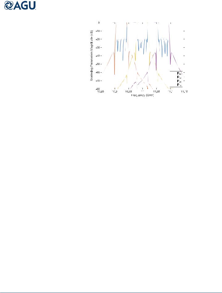
The response of the triplexer, directly after the assembling process is shown in Figure 11. It can be observed that the obtained response is already quite close to the final target specifications, indicating the e ectiveness of the design strategy. In particular, most of the filter poles in each channel can be di erentiated, with a level of return loss better than 10 dB. Also, center frequency and bandwidth are quite close to the specified values in all three channels.
Since the performance of the structure is quite close to the target response, a final optimization procedure can be applied quite e ectively. This final optimization procedure is carried out with the full-wave simulator, following the iterative strategy already introduced at the circuit level [Cameron and Yu, 2007]. This strategy will assure fast convergence of the procedure, limiting at each step the number of variables to be optimized.
In general, the transmission line sections of the manifold are first optimized alone. This simple optimization already introduces a big improvement in the response of the multiplexer. This is because the interactions between the channel filters through the manifold are very strong, and small imprecisions during the design procedure produce rather large deviations in the expected behavior of the structure. At a later stage, the first few elements of each channel filter (coupling windows and cavities) are also introduced in the optimization process. For the channel filters proposed in this work, this step results to be also simple. This is because the filter structure is terminated by single-mode first and last cavities. In this way, the optimization of the more complex dual-mode cavities, placed internally in the filter structure, requires very small adjustments.
If necessary, these steps are repeated in an iterative fashion until all channels are correctly recovered. In Figure 12 we include the full-wave response of the triplexer after this final optimization process. It can be observed very good electrical performance of the structure. By comparing the response of the final triplexer with the behavior of the ideal circuit model in Figure 6, it can be verified that all initial specifications are correctly met in the three considered channels.
Table 2. Geometrical Parameters in (mm) of the Manifold Line Sections Obtained Directly
After the Design Process
|
Parameter |
l1 |
l2 |
l3 |
ls1 |
ls2 |
ls3 |
|
|
Value |
15.785 |
15.1964 |
21.1448 |
30.2584 |
33.0895 |
30.5236 |
|
|
|
|
|
|
|
|
|
|
|
|
|
|
|
|
|
|
|
PONS ABENZA ET AL. MULTIPLEXER WITH ALL-INDUCTIVE FILTERS 1073

Radio Science |
|
|
|
|
|
10.1002/2016RS005999 |
|||
|
|
||||||||
|
|
||||||||
|
Table 3. Geometrical Parameters in (mm) of the Rectangular Waveguide Filters After Their Isolated Design in FEST3Da |
||||||||
|
Parameter |
w1 |
a1 |
d1 |
t2 |
x1 |
a2 |
d2 |
x2 |
|
Channel 1 |
5.898 |
19.05 |
18.394 |
0.965 |
7.361 |
30.316 |
30.096 |
8.150 |
|
Channel 2 |
5.679 |
19.05 |
18.709 |
1.036 |
7.772 |
30.527 |
30.297 |
8.278 |
|
Channel 3 |
5.709 |
19.05 |
18.988 |
0.957 |
7.838 |
30.738 |
30.504 |
8.472 |
|
Parameter |
t3 |
x3 |
a3 |
d3 |
x4 |
t4 |
d4 |
w5 |
|
Channel 1 |
1.038 |
8.426 |
30.193 |
30.158 |
7.294 |
0.925 |
17.973 |
7.241 |
|
Channel 2 |
1.030 |
8.529 |
30.399 |
30.367 |
7.302 |
0.875 |
18.193 |
7.392 |
|
Channel 3 |
1.017 |
8.461 |
30.608 |
30.576 |
7.552 |
0.872 |
18.455 |
7.426 |
|
aThese dimensions correspond to Figure 3. Rest of parameters are in (mm): t1 |
= 1.5, a1 = a4 |
= 19.05, w2 |
= w3 = |
|||||
|
w4 = 3.0, and t5 = 2.0 and are fixed for all three channel filters. |
|
|
|
|
||||
The final relevant lengths of the mainfold are collected in Table 4.
Finally, for the sake of completeness, Tables 5–7 collect the final dimensions of the three channel filters including the relative errors with respect to the initial design.
In general, it can be noticed that the first and last filters contain the largest errors. This is probably due to stronger interactions of these filters with the input port and the manifold short-circuited termination. The second filter contains relative errors consistently below 0.6%. A 3-D sketch of the designed triplexer is shown in Figure 13.
An additional important consideration that should be taken into account during the analysis of this structure is that the manifold, being in E-plane, spoils the H-plane symmetry of the filters. Consequently, the analysis of the whole device should be accomplished using the full set of TE and TM modes. Still, each channel filter can be optimized separately from the manifold using the described procedure. Following this strategy, the filters can be analyzed and optimized using 2-D models when they are separated from the manifold, which considerably increases numerical e ciency.
The structure was designed using the commercial software FEST3D [Carceller et al., 2014]. This software tool implements an integral equation formulation based on a multimode network representation of the waveguide discontinuities. Basically, accuracy is controlled with the number of basis functions used in the expansion on the unknown magnetic currents at the discontinuities and with the number of modes used to sum the Green’s functions of the integral equation. An additional important parameter is the number of accessible modes, which controls how many modes below cuto interact with nearby discontinuities. For the analysis of the whole triplexer, convergence was reached with 30 accessible modes, 250 basis functions, and 1500 Green’s functions modes.
Figure 11. Electrical response of the triplexer directly after connecting the isolated filters through the manifold structure.
PONS ABENZA ET AL. |
MULTIPLEXER WITH ALL-INDUCTIVE FILTERS |
1074 |