

диафрагмированные волноводные фильтры / e08e7cd0-a6af-44a6-a84b-4d2e9ab2014d
.pdfRadio Science |
|
|
|
|
|
|
|
10.1002/2016RS005999 |
||||
|
|
|
|
|
|
|
|
|
|
|
|
|
|
|
|
|
|
|
|
|
|
|
|
|
|
|
|
|
|
|
|
|
|
|
|
|
|
|
|
|
|
|
|
|
|
|
|
|
|
|
|
|
|
|
|
|
|
|
|
|
|
|
|
|
|
|
|
|
|
|
|
|
|
|
|
|
|
|
|
|
|
|
|
|
|
|
|
|
|
|
|
|
|
|
|
|
|
|
|
|
|
|
|
|
|
|
|
|
|
|
|
|
|
|
|
|
|
|
|
|
|
|
|
|
|
|
|
|
|
|
|
|
|
|
|
|
|
|
|
|
|
|
|
|
|
|
|
|
|
|
|
|
|
|
|
|
|
|
|
|
|
|
|
|
|
|
|
|
|
|
|
|
|
|
|
|
|
|
|
|
|
Figure 12. Response of the triplexer after applying a final optimization procedure.
On the contrary, convergence of each channel filter, using H-plane symmetry, was obtained with 5 accessible modes, 150 basis functions and 500 Green’s functions modes. The design was performed on a PC with Intel Xeon processor E5-2630 and clock frequency 2.40 GHz. The computational time needed for the analysis of the whole structure was 37 s for 250 frequency points. On the contrary, only 3.5 s were needed for the analysis of one isolated channel filter. This shows that the optimization of the isolated channel filters, which is one of the key steps in the design process, may be very fast.
The design of the structure is performed assuming ideal lossless materials. Once the design is finished, we can make an assessment on the expected losses in the structure. For the calculation of the losses, again the software FEST3D has been used, assuming that the surfaces are silver plated, as commonly done in space applications (with a resistivity of 1.6 10−8 Ω m). The expected minimum insertion losses at the center of the passband are approximately of 1.1 dB for the three channels.
3.2. H-Plane Manifold Multiplexer
In addition to the multiplexer design discussed in the previous section, an analogous strategy can be applied for the design of a similar triplexer but using a manifold composed of H-plane T-junctions. One of the advantages of this topology is that it remains completely 2-D, as shown in Figure 14, including channel filters and the manifold. Consequently, the complete analysis can be reduced to a two dimensional structure, being very e cient, for instance, following techniques such as those described in Perez Soler et al. [2007].
In Figure 14, it can be observed that the orientations of the three channel filters have been judiciously selected so as to fit all filters on the same side of the manifold. The filter of the central channel is the one having more limited space. This is due to the extended width needed in the dual-mode cavities. Other simpler filters such as those implemented in in-line topologies with single-mode cavities will be less limited in space. In any case, if the central filter cannot be fitted on the same side of the manifold, it can always be attached to the other side, at the expense of more footprint.
The response of the designed triplexer is shown in Figure 15. This response has again been obtained after first applying the design strategy presented in this paper and a subsequent final optimization process to correct for small inaccuracies. The level of precision achieved for this second design was very similar than the one obtained for the previous design. Overall, the response is very satisfactory, demonstrating the e ectiveness of the process described in this paper. The dimensions for this second design are collected in Table 8.
|
Table 4. Geometrical Parameters in (mm) of the Manifold After Final Optimization |
|
|
|||||
|
Parameter |
l1 |
l2 |
l3 |
ls1 |
ls2 |
ls3 |
|
|
Value (mm) |
16.229 |
15.014 |
23.203 |
29.538 |
30.998 |
30.848 |
|
|
|
|
|
|
|
|
|
|
PONS ABENZA ET AL. MULTIPLEXER WITH ALL-INDUCTIVE FILTERS 1075

|
Radio Science |
|
|
|
10.1002/2016RS005999 |
||
|
|
|
|
||||
|
|
|
|||||
|
|
Table 5. Individual Channel Filter 1 Parameter Variation From Initial Manifold Connection to |
|
||||
|
|
Final Optimization of the Triplexer |
|
|
|
|
|
|
|
Parameter |
Initial |
Optimized |
|
Er (%)) |
|
|
|
w1 |
5.898 |
6.82 |
0.922 |
13.51 |
|
|
|
a1 |
19.05 |
19.05 |
0 |
0.00 |
|
|
|
d1 |
18.394 |
18.113 |
−0.04 |
0.02 |
|
|
|
t2 |
0.965 |
0.77 |
−0.195 |
25.32 |
|
|
|
x1 |
7.361 |
7.266 |
−0.095 |
1.31 |
|
|
|
a2 |
30.316 |
30.322 |
0.06 |
0.02 |
|
|
|
d2 |
30.096 |
30.092 |
−0.004 |
0.01 |
|
|
|
x2 |
8.15 |
8.354 |
0.204 |
2.44 |
|
|
|
t3 |
1.038 |
1.004 |
−0.034 |
3.38 |
|
|
|
x3 |
8.426 |
8.387 |
−0.039 |
0.47 |
|
|
|
a3 |
30.193 |
30.193 |
0 |
0.00 |
|
|
|
d3 |
30.158 |
30.161 |
0.003 |
0.00 |
|
|
|
x4 |
7.294 |
7.296 |
0.032 |
0.44 |
|
|
|
t4 |
0.925 |
0.924 |
−0.001 |
0.11 |
|
|
|
d4 |
17.973 |
17.981 |
0.008 |
0.04 |
|
|
|
w5 |
7.241 |
7.236 |
−0.005 |
0.07 |
|
|
For the analysis of this second triplexer, convergence was reached with 6 accessible modes, 150 basis |
||||||
|
functions, and 900 Green’s functions modes. The analysis takes 4.6 s for 250 frequency points, for the whole |
||||||
|
triplexer. As compared to the previous structure, this one results to be much more e cient in terms of global |
||||||
|
computational time and memory resources. As already commented, this is because the H-type manifold pre- |
||||||
|
serves the all-inductive nature of the filter discontinuities. As such, the whole structure can be analyzed using |
||||||
|
H-type symmetry, which leads to a drastic increase in numerical e ciency. |
|
|
||||
|
For the triplexer with H-plane manifold, the expected insertion losses using silver plated material are again |
||||||
|
of 1.1 dB for the three channels. This shows that the losses introduced by the H-plane manifold are similar to |
||||||
|
those introduced by the E-plane manifold. |
|
|
|
|
||
|
|
|
|||||
|
|
Table 6. Individual Channel Filter 2 Parameter Variation From Initial Manifold Connection to |
|
||||
|
|
Final Optimization of the Triplexer |
|
|
|
|
|
|
|
Parameter |
Initial |
Optimized |
|
Er (%)) |
|
|
|
w1 |
5.679 |
5.546 |
−0.133 |
2.39 |
|
|
|
a1 |
19.05 |
19.05 |
0 |
0.00 |
|
|
|
d1 |
18.709 |
18.754 |
0.045 |
0.24 |
|
|
|
t2 |
1.036 |
1.029 |
−0.007 |
0.68 |
|
|
|
x1 |
7.772 |
7.816 |
0.044 |
0.56 |
|
|
|
a2 |
30.527 |
30.527 |
0 |
0.00 |
|
|
|
d2 |
30.297 |
30.299 |
0.002 |
0.00 |
|
|
|
x2 |
8.278 |
8.304 |
0.026 |
0.31 |
|
|
|
t3 |
1.03 |
1.023 |
−0.007 |
0.68 |
|
|
|
x3 |
8.529 |
8.528 |
−0.001 |
0.01 |
|
|
|
a3 |
30.399 |
30.399 |
0 |
0.00 |
|
|
|
d3 |
30.367 |
30.368 |
0.001 |
0.00 |
|
|
|
x4 |
7.302 |
7.301 |
−0.001 |
0.01 |
|
|
|
t4 |
0.875 |
0.874 |
−0.001 |
0.11 |
|
|
|
d4 |
18.193 |
18.191 |
−0.002 |
0.01 |
|
|
|
w5 |
7.392 |
7.387 |
−0.005 |
0.07 |
|
|
|
|
|
|
|||
PONS ABENZA ET AL. |
|
MULTIPLEXER WITH ALL-INDUCTIVE FILTERS |
|
1076 |
|||

Radio Science |
10.1002/2016RS005999 |
|
|
Table 7. Individual Channel Filter 3 Parameter Variation From Initial Manifold Connection to
Final Optimization of the Triplexer
Parameter |
Initial |
Optimized |
|
Er (%)) |
w1 |
5.709 |
6.056 |
0.347 |
5.73 |
a1 |
19.05 |
19.05 |
0 |
0.00 |
d1 |
18.988 |
18.928 |
−0.06 |
0.32 |
t2 |
0.957 |
0.814 |
−0.143 |
17.56 |
x1 |
7.838 |
6.929 |
−0.909 |
13.12 |
a2 |
30.738 |
30.726 |
−0.012 |
0.04 |
d2 |
30.504 |
30.52 |
0.016 |
0.05 |
x2 |
8.472 |
7.653 |
−0.819 |
10.7 |
t3 |
1.017 |
0.96 |
−0.057 |
5.94 |
x3 |
8.461 |
8.413 |
−0.048 |
0.57 |
a3 |
30.608 |
30.608 |
0 |
0.00 |
d3 |
30.576 |
30.575 |
−0.001 |
0.01 |
x4 |
7.552 |
7.694 |
0.142 |
1.84 |
t4 |
0.872 |
0.855 |
−0.014 |
1.63 |
d4 |
18.455 |
18.462 |
0.007 |
0.04 |
w5 |
7.426 |
7.426 |
0 |
0.00 |
Practical considerations for real applications involve sensitivity issues about the designed component. A sensitivity study has been carried out for the two triplexers designed in this paper. The study has revealed that the E-plane manifold triplexer is less sensitive than the H-plane manifold triplexer. For the E-plane manifold device, a 15 dB return loss can still be expected with errors of 5 μm, while 2 μm are needed to the H-plane case. This shows that tuning screws are needed for a practical implementation.
For the proposed technology, it has been shown that the most sensitive parameters a ecting the response of the channel filters are the resonant frequencies of the resonators. However, sensitivity with coupling elements is much lower. For instance, in Guglielmi et al. [2001] the desired responses of the filters could be recovered adding only screws to tune the resonant frequencies of the resonators in the dual-mode cavities. The tuning could be performed adding one screw in the center of the single-mode cavities, and four screws displaced from the center in the dual-mode cavities, as shown in Guglielmi et al. [2001].
For the tuning of the whole multiplexer, the most critical components are the couplings of the filters attached to the manifold. In this sense, the structure proposed in this work is very convenient, since these couplings are formed with standard inductive windows in traditional single-mode waveguide cavities. Consequently, it is expected that no tuning mechanism is required in these critical coupling elements. If the initial critical couplings are preserved, then the tuning of the internal resonators in each filter can be made with little
Figure 13. 3-D sketch of the designed E-plane manifold triplexer.
PONS ABENZA ET AL. |
MULTIPLEXER WITH ALL-INDUCTIVE FILTERS |
1077 |
Radio Science |
10.1002/2016RS005999 |
|
|
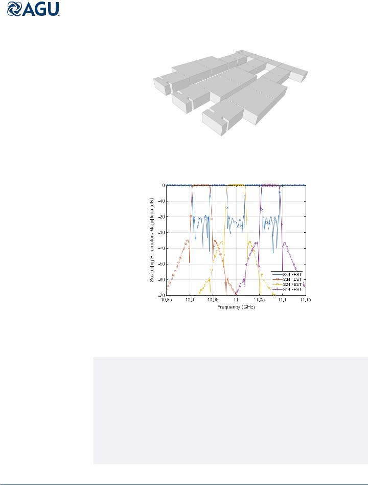
Figure 14. 3-D sketch of the designed H-plane manifold triplexer.
Figure 15. Scattering parameters of the H-plane manifold triplexer.
Table 8. Geometrical Parameters in (mm) of the Three Channel Filters After Applying a Final Optimization Process, for the
H-plane Manifold Triplexera
Parameter |
w1 |
a1 |
d1 |
t2 |
x1 |
a2 |
d2 |
x2 |
Channel 1 |
7.097 |
19.05 |
18.008 |
0.906 |
7.253 |
30.318 |
30.097 |
8.313 |
Channel 2 |
7.397 |
19.05 |
18.126 |
0.813 |
7.292 |
30.527 |
30.302 |
8.434 |
Channel 3 |
7.521 |
19.05 |
18.363 |
0.901 |
7.836 |
30.736 |
30.508 |
8.283 |
Parameter |
t3 |
x3 |
a3 |
d3 |
x4 |
t4 |
d4 |
w5 |
Channel 1 |
1.034 |
8.236 |
30.193 |
30.163 |
7.364 |
0.921 |
17.965 |
7.254 |
Channel 2 |
0.999 |
8.166 |
30.398 |
30.370 |
7.539 |
0.906 |
18.229 |
7.275 |
Channel 3 |
0.992 |
8.429 |
30.607 |
30.580 |
6.316 |
0.860 |
18.471 |
7.487 |
|
|
|
|
|||||
aThese dimensions correspond to Figure 3. Rest of parameters are (in mm): t1 |
= 1.5, a1 = a4 |
= 19.05, w2 |
= w3 = |
|||||
w4 = 3.0, and t5 = 2.0 and are fixed for all three channel filters. |
|
|
|
|
||||
PONS ABENZA ET AL. |
MULTIPLEXER WITH ALL-INDUCTIVE FILTERS |
1078 |
Radio Science |
|
|
10.1002/2016RS005999 |
|||
|
|
|
|
|
|
|
|
|
|
|
|
|
|
|
|
|
|
|
|
|
|
|
|
|
|
|
|
|
|
|
|
|
|
|
|
|
|
|
|
|
|
|
|
|
|
|
|
|
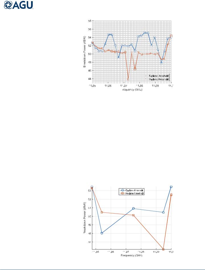
Figure 16. Multipactor thresholds obtained for the most critical filter in E-plane and H-plane manifold triplexers designed in the work (channel 1). Thresholds are shown as a function of frequency inside the passband.
interactions from the rest of the network. Consequently, the tuning of each filter can proceed almost independently, thus simplifying the tuning task of the whole multiplexer.
For space applications, it is also important to assess the behavior of the devices to high power e ects, such as multipactor [Vicente et al., 2005b]. Since the structures proposed are all-inductive, it is expected that multipactor thresholds will be determined essentially by the height of waveguides. Detailed studies have been carried out using the same software tool FEST3D for the two triplexers presented in this paper, using the nominal waveguide height of (b = 9.525 mm) and assuming silver plated walls. For the simulations, an initial population of 500 electrons were used, which usually leads to accurate predictions [Vicente et al., 2005a]. We have verified that in both cases the most critical filter is the one which is closest to the manifold short circuit (channel 1 in Figure 1). In addition, the most critical elements in this filter are the dual-mode cavities. Although multipactor can be triggered in the manifold sections, the thresholds are always higher than in the all-inductive dual-mode cavities. In Figure 16 we present the lowest thresholds obtained for channel 1 filters in both triplexers designed in this paper.
Figure 17. Minimum multipactor thresholds obtained at five selected frequencies, resulting from five experiments conducted with the software FEST3D.
PONS ABENZA ET AL. |
MULTIPLEXER WITH ALL-INDUCTIVE FILTERS |
1079 |

Radio Science |
10.1002/2016RS005999 |
|
|
Acknowledgments
This work was developed with financial support from Spanish Ministry of Education under grant TEC2013-47037-C5-5-R, Fundacion Seneca Region de Murcia with grant 19494/PI/14, and European Feder funding. All data presented in the work are listed in the tables and figures included in the paper. All results can be reproduced from these tables and figures.
It can be observed that both triplexers have similar thresholds in the range 44–50 dBW. The peaks in the curves are due to higher order multipactor. This occurs when multipactor is triggered in electrically large gaps, as it is the case in our filter structures due to the rather large waveguide height used in the standard (b = 9.525 mm).
Since multipactor is a random phenomenon, we have also run five experiments at five frequencies for the critical filter (channel 1). The selected frequencies are the two transmission zeros (11.047 GHz, 11.100 GHz), the 3 dB crossings (11.054 GHz, 11.095 GHz), and the center frequency of the filter (11.075 GHz). Figure 17 shows the minimum thresholds obtained in the five experiments at these five frequencies, for both the E-plane and H-plane manifold triplexers. The statistical analysis shows that the thresholds tend to decrease at the 3 dB crossings. This is related to a higher stored energy in the cavities at these frequencies, as reported in the literature [Kishi and Nakazawa, 1963; Mendoza et al., 2012]. In any case, the statistical analysis confirms the minimum thresholds to be expected in the designed devices. It can be seen that these levels are high due to the all-inductive nature of the implementations introduced in this paper. However, these thresholds should be lowered, if screws are used to tune the resonant frequencies of the cavities as previously commented.
4. Conclusions
In this contribution, a detailed design procedure of manifold multiplexers has been given. The main novelty of the proposed structure is the combination of the manifold configuration with channel filters implemented in all-inductive dual-mode technology. In this way compact and simple structures are obtained, while still being able to implement complex transfer functions. An example is illustrated with the design of a triplexer with high isolation between channels through the use of two transmission zeros in each filter. It is shown that the proposed design strategy leads to an accurate dimensioning of all parts of the structure, which can easily be refined with a final optimization process.
References
Amari, S., G. Tadeson, J. Cihlar, R. Wu, and U. Rosenberg (2004), Pseudo-elliptic microstrip line filters with zero-shifting properties,
IEEE Microwave Wireless Components Lett., 14(7), 346–348.
Brumos, M., S. Cogollos, M. Martinez, P. Soto, V. E. Boria, and M. Guglielmi (2014), Design of waveguide manifold multiplexers with dual-mode filters using distributed models, in IEEE MTT-S International Microwave Symposium Digest, pp. 1–4, IEEE, Tampa, Fla.
Cameron, R. J., and M. Yu (2007), Design of manifold-coupled multiplexers, IEEE Microwave Mag., 8(5), 46–59.
Cameron, R. J., C. M. Kudsia, and R. R. Mansour (2007), Microwave Filters for Communication Systems, pp. 379–386, Wiley, N. J. Carceller, C., F. Perez, J. Gil, C. Vicente, V. Boria, B. Gimeno, and M. Guglielmi (2014), FEST3D a commercial EM solver using the BI-RME
method, in International Conference on Numerical Electromagnetic Modeling and Optimization for RF, Microwave, and Terahertz Applications, pp. 1–4, IEEE MTT-S, Pavia, Italy.
Carceller, C., P. Soto, V. Boria, M. Guglielmi, and J. Gil (2015), Design of compact wideband manifold-coupled multiplexers, IEEE Trans. Microwave Theory Tech., 63(10), 3398–3407.
Garay, J. R. M., J. A. Ruiz-Cruz, and J. M. Rebollar (2005), Full-wave design of H-plane contiguous manifold output multiplexers using the fictitious reactive load concept, IEEE Trans. Microwave Theory Tech., 53(8), 2628–2632.
Guglielmi, M., P. Jarry, E. Kerherve, O. Roquebrun, and D. Schmitt (2001), A new family of all-inductive dual-mode filters, IEEE Trans. Microwave Theory Tech., 49(10), 1764–1769.
Kishi, G., and K. Nakazawa (1963), Relations between reactive energy and group delay in lumped-constant networks, IEEE Trans. Circuit Theory, 10(1), 67–71.
Martinez Martinez, D., A. Alvarez Melcon, and M. Martinez Mendoza (2014), Band-pass waveguide filters and multiplexers design by the structure segmentation technique, Master thesis, Tech. Univ. of Cartagena, Cartagena, Spain.
Martinez Mendoza, M., D. Martinez Martinez, D. Canyete Rebenaque, and A. Alvarez Melcon (2015), Enhanced topologies for the design of dual-mode filters using inductive waveguide structures, Radio Sci., 50, 66–77, doi:10.1002/2014RS005419.
Mendoza, M. M., F. Seyfert, C. Ernst, and A. A. Melcon (2012), Formal expression of sensitivity and energy relationship in the context of the coupling matrix, IEEE Trans. Microwave Theory Tech., 60(11), 3369–3375.
Newell, P., and T. S. Bird (1994), E ects of mutual coupling in the design of high-performance multifeed satellite antennas, Radio Science, 29(1), 145–152, doi:10.1029/93RS02503.
Perez Soler, F., F. Quesada Pereira, D. Canete Rebenaque, J. Pascual Garcia, and A. Alvarez Melcon (2007), E cient integral equation formulation for inductive waveguide components with posts touching the waveguide walls, Radio Sci., 42, RS6002, doi:10.1029/2006RS003591.
Pozar, D. M. (2005), Microwave Engineering, 3rd ed., John Wiley, New York.
Shang, X., Y. Wang, W. Xia, and M. J. Lancaster (2013), Novel multiplexer topologies based on all-resonator structures, IEEE Trans. Microwave Theory Tech., 61(11), 3838–3845.
Tao, Y., Z. Shen, and G. Liu (2009), Equivalent circuit model of square waveguide T-junction for ortho-mode transducers, in IEEE MTT-S International Microwave Symposium Digest, pp. 1013–1016, IEEE, Boston, Mass.
Vicente, C., M. Mattes, D. Wolk, H. Hartnagel, J. Mosig, and D. Raboso (2005a), FEST3D—A simulation tool for multipactor prediction, in International Workshop on Multipactor, Corona and Passive Intermodulation in Space RF Hardware, pp. 1–7, ESA/ESTEC, Noordwijk, Netherlands.
Vicente, C., M. Mattes, D. Wolk, B. Mottet, H. L. Hartnagel, J. Mosig, and D. Raboso (2005b), Multipactor breakdown prediction in rectangular waveguide based components, in IEEE MTT-S International Microwave Symposium Digest, pp. 1055–1058, IEEE, Long Beach, Calif.
Xia, W., X. Shang, and M. J. Lancaster (2014), All-resonator-based waveguide diplexer with cross-couplings, Electron. Lett., 50(25), 1948–1950.
PONS ABENZA ET AL. |
MULTIPLEXER WITH ALL-INDUCTIVE FILTERS |
1080 |