

диафрагмированные волноводные фильтры / f1026e1c-bbbc-4fc8-a4f2-8015fab91e70
.pdfIEEE TRANSACTIONS ON TERAHERTZ SCIENCE AND TECHNOLOGY, VOL. 2, NO. 6, NOVEMBER 2012 |
629 |
WR-3 Band Waveguides and Filters Fabricated Using SU8 Photoresist Micromachining Technology
Xiaobang Shang, Maolong Ke, Yi Wang, Member, IEEE, and Michael J. Lancaster, Senior Member, IEEE
Abstract—This paper demonstrates a two-layer SU8 photoresist micromachining technology that has similar performance to conventionally machined metal. The technology is demonstrated in the WR-3 band (220–325 GHz). Three different WR-3 band circuits, namely a WR-3 band straight through waveguide, a bandpass filter and a dual-band filter are demonstrated. For the measurements, a conventionally precision machined metal block was used for the WR-3 band waveguide and the bandpass filter to achieve good calibration and accurate interconnection with standard waveguide flanges; whereas, for the dual-band filter, two back-to-back right-angle bends are added in order to achieve accurate, reliable waveguide interconnection without using the metal block. A measured average insertion loss of 0.03 dB/mm has been achieved for the 14.97 mm long straight through waveguide. This is comparable to the loss of around 0.02 dB/mm for a standard metal waveguide at this frequency. The fifth-order waveguide filter exhibits an 8% 3 dB bandwidth at a central frequency of around 300 GHz. The minimum passband insertion loss was measured to be around 1 dB and the return loss was better than 10 dB throughout the passband. The filter results showed a notable improvement over those obtained from the separate SU8 layer technique that was also used to make the same devices for comparison. To further demonstrate the advantages of the new two-layer SU8 micromachining technique, the dual-band filter included isolated regions in the waveguide channels that would have not been possible for micromachining using the previous separate single layer technique. The performance of the micromachined dual band filter was excellent in terms of very low insertion losses on both passbands.
Index Terms—Filter, millimeter wave (mm-wave) devices, SU8 micromachining, terahertz filters, waveguide, WR-3 band.
I. INTRODUCTION
T HERE is a growing interest in millimeter-wave (mm-wave) and terahertz components in the frequency range from 100 GHz to 10 THz for potential applications in security scanning, atmospheric monitoring, medical imaging and ultrafast wireless communications [1], [2]. Traditionally, metal
Manuscript received June 02, 2012; revised July 31, 2012; accepted September 07, 2012. Date of publication October 24, 2012; date of current version December 04, 2012. The work was supported by the U.K. Engineering and Physical Science Research Council (EPSRC) under Contract EP/H029656/1.
X.Shang and M. J. Lancaster are with the School of Electronics, Electrical and Computer Engineering, the University of Birmingham, B15 2TT, U.K. (e-mail: x.shang@bham.ac.uk; m.j.lancaster@bham.ac.uk).
M.Ke was with the School of Electronics, Electrical and Computer Engineering, the University of Birmingham, U.K. He is now with the Dynex Semiconductors Ltd., Lincoln LN6 3LF, U.K. (e-mail: mao2011.ke@gmail.com)
Y.Wang was with the School of Electronics, Electrical and Computer Engineering, the University of Birmingham, U.K. He is now with the School of Engineering, University of Greenwich (Medway Campus), Kent ME4 4TB, U.K.
Color versions of one or more of the figures in this paper are available online at http://ieeexplore.ieee.org.
Digital Object Identifier 10.1109/TTHZ.2012.2220136
milling is used to make passive components such as waveguides and filters. However, as the operating frequency continues to increase and device dimensions continue to decrease, traditional metal milling methods are becoming increasingly time-consuming and expensive for making such components. Photolithographic based micromachining technology has therefore attracted growing attention due to its high-dimensional accuracy, high achievable structure aspect ratio and a capability of large scale inexpensive production. Many different micromachining technologies have been reported in literature, among them three have been found most suitable for thick layer or three-dimensional (3D) fabrication, namely: Si deep reactive ion etching (DRIE) [3], [4]; LIGA-based thick layer electroplating [5], [6] and SU8 photoresist [7]–[11]. Previously we have compared these three technologies and found thick layer SU8 photoresist technology affords good dimensional accuracy and at the same time with low capital investment required [12], therefore making it a highly desirable choice for high precision and high performance applications. However, as the operating frequency rises to 300 GHz and above, device performance of micromachined circuits has not been comparable to the precision CNC machined circuits. For example, insertion loss for a precision CNC machined waveguide at 300 GHz frequency is around 0.02 dB/mm, whereas the best reported insertion loss for micromachined waveguides is typically an order of magnitude higher 
 0.2 dB/mm
 , as shown in Table I. Performance improvement is therefore of high priority if the micromachined circuits are to compete with the traditional CNC precision machined circuits. As reported previously, we started our microfabrication investigation with a separate single-layer SU8 processing technique, and produced very good performance for a
  -band waveguide and a waveguide filter [13]. However, as frequency increased to around 300 GHz, the device performance was less impressive [14], [15]. The average sidewall roughness of our micromachined SU8 circuits has been measured with AFM to be very low [16]; of the order of a few tens of nanometers, hence the roughness of the waveguide walls should not be a major factor for the reduced performance. The previous waveguides were formed by joining layers of metal coated SU8, and it is therefore believed that the joins may have an adverse effect on performance. We have therefore developed a fully joined two-layer SU8 process. In this technique two layers are produced in one processing step removing any need for separate joints. Previously, this type of joined SU8 multilayers technique has found some applications in microfluidics [17], [18], its use for millimeter-wave circuits has been reported [10], but for different context circuits at 1.6 THz; and there was no discussion of the attenuation. In
2156-342X/$31.00 © 2012 IEEE

630 |
IEEE TRANSACTIONS ON TERAHERTZ SCIENCE AND TECHNOLOGY, VOL. 2, NO. 6, NOVEMBER 2012 |
TABLE I
COMPARISON OF WR-3 BAND WAVEGUIDE CIRCUITS
[11], a conceptually similar SU8 two-layer process was employed to fabricate three straight through waveguide sections with operating frequencies from 110 to 320 GHz. Among them the WR-3 band waveguide was measured to have an average insertion loss of 0.75 dB/mm. The fabrication process was explained very generally in [11].
In the separate single-layer micromachining process, a WR-3 waveguide device was split into 4 equally thick separate layers. SU8 is spun onto a silicon wafer and all the layers were made by photolithography using a single, one mask processing step. The layers were then released from Si substrate, metal coated and then bonded/assembled together. The drawback of this method is that it is difficult to avoid localized air gaps between the different layers because the SU8 surfaces are not perfectly flat. Typically, thickness non-uniformity is of the order of several micrometers. When two uneven surfaces come into contact, air gaps can form along the joining surface regions. Air gaps have a deleterious effect on device performance, resulting in current leakage and higher loss.
In this paper, a new multilayer SU8 processing technology is developed for 300 GHz components. The previous separate layers processing technique was also used to make the same devices for comparison. We then proceeded to design a dual band filter using the new fully joined SU8 two-layer processing
Fig. 1. A cross-sectional view from either end of the waveguide and the bandpass filter which consists nominally four layers, each layer has a thickness of 432  m,
m, 


 m,
m, 


 m.
m.
technique, which is not possible for the previous technique. The paper is organized as follows: The device design and structure details are presented in Section II, which is followed by a detailed description of fabrication procedure in Section III. Measurements and discussions will be presented in Section IV and finally conclusions in Section V.
II. DEVICE DESIGN AND STRUCTURE DETAILS
Both the WR-3 straight through waveguide and the fifth-order bandpass filter consist of nominally four equally thick layers of 432  m each. Fig. 1 illustrates their cross sectional view. Both devices were split in the E-plane to minimize possible

SHANG et al.: WR-3 BAND WAVEGUIDES AND FILTERS |
631 |
Fig. 2. Illustration of the fifth-order asymmetric-capacitive-iris coupled WR-3 single-band filter. Drawing is not to scale. The turquoise blue part in the middle of the structure represents the hollow channel. The surrounding conductors have been set to be transparent to offer a clearer view. Some critical dimensions of
the filter: |
|
|
|
|
|
|
|
|
|
|
|
|
|
|
|
|
|
|
|
m, |
|
|
|
|
|
|
|
|
|
|
|
|
|
|
|
|
|
|
|
|
|
|
m, |
|
|
|
|
|
|
|
|
|
|
|
|
|
|
|
|
|
|
|
m, |
|
|
|
|
|
|
|
|
|
|
|
|
|
|
|
|
|
|
m, |
|||||||||||||||||||||
|
|
|
|
|
|
|
|
|
|
|
|
|
|
|
|
|
|
|
|
m, |
|
|
|
|
|
|
|
|
|
|
|
|
|
|
|
|
|
|
|
m, |
|
|
|
|
|
|
|
|
|
|
|
|
|
|
|
|
|
|
|
m, |
|
|
|
|
|
|
|
|
|
|
|
|
|
|
|
|
|
m, |
|
|
|
|
|
|
|
|
|
|
|
|
|
|
|
|
m, |
||||||||
|
|
|
|
|
|
|
|
|
|
|
|
|
|
|
|
|
m. |
|
|
|
|
|
|
|
|
|
|
|
|
|
|
|
|
|
|
|
|
|
|
|
|
|
|
|
|
|
|
|
|
|
|
|
|
|
|
|
|
|
|
|
|
|
|
|
|
|
|
|
|
|
|
|
|
|
|
|
|
|
|
|
|
|
|
|
|
|
|
|
|
|
|
|
|
|
|
|
|
|
|
||||
losses. For the bandpass filter, a fifth-order Chebyshev type with a ripple bandwidth of 9% centered at 300 GHz has been designed following the approach in [19]. To meet the filter specification the external  and the coupling coefficients between
resonators are calculated to be: |
|
|
|
|
|
|
|
|
|
|
|
|
|
|
|
|
|
|
, |
|
|
|
|
|
|
|
|
|
|
|
|
|
||||||||||||||||||||||||||||
|
|
|
|
|
|
, |
|
|
|
|
|
|
|
|
|
|
|
|
|
|
|
|
|
|
|
|
|
[19]. In order to be consistent with |
||||||||||||||||||||||||||||||||
|
|
|
|
|
|
|
|
|||||||||||||||||||||||||||||||||||||||||||||||||||||
|
|
|
|
|
||||||||||||||||||||||||||||||||||||||||||||||||||||||||
the micromachining process of this layered structure, all capacitive coupling irises have been adopted here to provide the required external  and coupling coefficients, as shown in Fig. 2. Full-wave modelling was carried out in CST [20], and Fig. 2 illustrates some critical dimensions achieved after optimization.
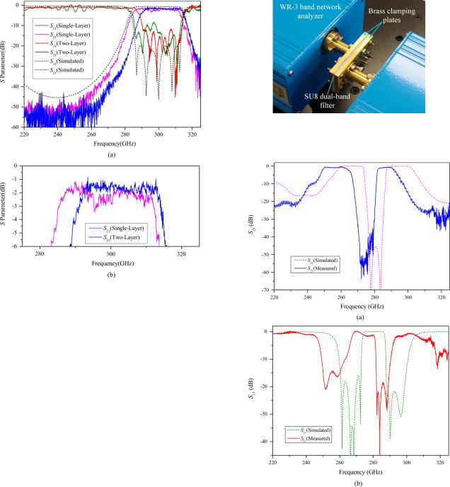
A WR-3 band eighth-order dual-band waveguide filter, as shown in Fig. 3(a), with a center frequency of 280 GHz and a fractional bandwidth of 13%, has also been designed and fabricated using the joined two-layer SU8 micromachining processing technology. The design principles of this WR-3 filter are discussed in terms of the design of an  -band (i.e., WR-90) dual-band waveguide filter, as reported in [21]. A full-wave optimization was performed and the final dimensions are shown in Fig. 3(b). Two H-plane bends, as presented in [15], have been employed here for accurate and secure connection with measurement ports. Note that, there are two isolated parts in the second and third SU8 layer, as highlighted in Fig. 3(b). If the circuit was made using the single layer technique, then these isolated structures would not be connected to the rest of a layer, and would fall away from the circuit once the layer became free standing. This prevents the usage of single SU8 layer fabrication technique for this circuit.
III. FABRICATION DETAILS
Initially the through waveguide and the bandpass filter were fabricated using all four layers, each device was fabricated using one mask and processed in a standard photolithographic procedure. The four separate layers were then released from the Si substrate, silver coated and finally bonded together by applying adhesive at the device edges. As mentioned above, the disadvantage of such a method is that localized air gaps can exist after bonding because the surfaces of the SU8 layers were not perfectly flat. When two uneven surfaces were brought into contact, localized air gaps would form. These air gaps are likely to lead to increased insertion losses due to current leakage. In order
Fig. 3. (a) Illustration of the eighth-order WR-3 band dual-band waveguide filter with two H-plane back-to-back bends. For the sake of clear view, only the hollow waveguide channel (turquoise blue part) is shown in the figure. The topology of the dual-band filter is also shown. (b) A schematic side-view diagram of the dual-band filter. This filter structure is symmetric to the middle
dotted line. Some critical dimensions of the filter: |
|
|
|
|
|
|
|
|
|
|
|
m, |
|
|
|
|
|
|
|
|
|
|
||||||||||||||||||||||||||||||||||||||||||
|
|
|
|
|
m, |
|
|
|
|
|
m, |
|
|
|
|
|
|
|
|
|
|
|
|
m, |
|
|
|
|
|
|
|
|
|
|
|
|
|
|
m, |
|
|
|
|
|
|
|
m, |
|
|
|
|
|
|
|||||||||||
|
|
|
|
|
m, |
|
|
|
|
|
m, |
|
|
|
|
|
|
|
|
|
|
|
|
m, |
|
|
|
|
|
|
|
|
|
|
|
m, |
|
|
|
|
|
|
|
|
|
m, |
||||||||||||||||||
|
|
|
|
|
|
|
|
|
|
|
m, |
|
|
|
|
m, |
|
|
|
|
|
|
|
|
m. |
|
|
|
|
|
|
|
|
|
|
|
|
|
|
|
|
|
|
|
|
|
|
|
|
|
|
|
|
|
||||||||||
to eliminate the air gaps, we have used a two-layer SU8 processing technology. Instead of making four separate layers, and then bonding them together, two layers were processed in succession to form a fully joined one half of the waveguide or the filter. The full processing details are as follows. A 4” Si wafer of around 


 m in thickness was used as a substrate and
5.2 g of SU8 50 photoresist were spun onto the substrate. Prebake was carried out on a precisely leveled hotplate and temperature was stepped from 65  C for about 20 min to 95
  C for 4-1/2 hours. The main purpose of the initial baking step at 65
  C was to assist self-planarization of the SU8 photoresist and improve the uniformity of the final processed layers. This happens because the SU8 photoresist becomes less viscous at the elevated temperature and its mobility enhanced; therefore the self planarization process proceeded on the precision leveled hotplate. The second baking step at 95
  C was to dry out the solvent. The wafer was then exposed under a mercury lamp UV source from a Canon PLA-510 mask aligner. The mercury lamp emits three main lines at 365, 405, and 436 nm in addition to a broad but weak background level. Initially an L39 optical filter was used to filter out lines under 400 nm and the wafer was exposed 5
  40 s in order to expose through the thick SU8 layer. It is well known that long wavelength signal lines such as the 405 nm line can penetrate much deeper into SU8 than the 365 nm line, but it is less effective in generating a strong acid for cross linking [9]. A PL360 optical filter was then used to filter out signals under 360 nm, so the main i-line 365 nm signal

632 |
IEEE TRANSACTIONS ON TERAHERTZ SCIENCE AND TECHNOLOGY, VOL. 2, NO. 6, NOVEMBER 2012 |
Fig. 4. Schematic diagram of some key steps for SU8 two-layer processing.
was used to expose the SU8 photoresist for 3  40 s. Alignment marks are transferred from the first mask onto the first SU8 layer during this exposure stage, which were then used to align with the second mask later. The wafer was then softly baked at 70
  C for 15 min to allow for weak crosslinking to take place, and at the same time avoid too much stress between the crosslinked SU8 and Si substrate. Another 5.2 g of fresh SU8 was then added onto the sample and the fresh solvent was dried out at 70
  C for about 9 hours. Once again this lower temperature baking was designed to reduce the stress between the SU8 and Si substrate. The sample was then carefully aligned under the mask aligner with the help of alignment marks, so that the second layer lay precisely on top of the first. The exposure details are the same as before for the first layer. After the second exposure, the wafer was post-exposure baked at 65
  C for 5 min followed by

 C for 30 minutes to allow for strong crosslinking across all the exposed areas. During the second exposure stage, the long wavelength signal lines from the mercury lamp was able to penetrate all the way through both SU8 layers to reach the Si substrate, hence both layers were crosslinked and joined together during the second post-exposure baking stage. Finally the wafer was developed in EC solvent for 45 min with an in-house designed agitation jig and released from the Si substrate through a sodium hydroxide solution. Fig. 4 displays the schematic diagram of some key steps for the aforementioned SU8 two-layer processing procedure.
The final product is a fully joined two layers SU8 structure forming one half of the waveguide/filter device. After cleaning thoroughly with running de-ionized water for 2 min followed by ultrasonic bath for 15 min, the pieces were then blown dry and loaded into a vacuum chamber for metallization. A Cressington 308 metal coater was used for metallization, which started with oxygen plasma cleaning for 45 s, followed by a thin Cr sputtering layer of around 5 nm for improved adhesion, and finally a 2  m thick silver layer was thermally evaporated onto the device to form the main conducting layer. The sample holder rotated continuously at a tilted angle in order to coat the important sidewalls. Fig. 5 shows photos of one half of the silver coated waveguide (a) and filter (b).
Fig. 5. (a) Photo of one half of a silver-coated waveguide and (b) one half of a silver-coated filter. The size of both halves is 14.97 mm  10 mm
10 mm  0.864 mm.
The alignment between the two halves of the SU-8 circuit is one essential factor for the successful realization of layered micromachined circuits. In this work, four precision metal pins have been utilized to align these two halves. In order to facilitate the fitting operation, the diameter of pinholes is designed to be 20  m larger than their matching pins, allowing a maximum misalignment between the two halves of 20
  m. According to CST simulations, this misalignment will not have a significant impact on the WR-3 band waveguides’ and filters’ performance.
IV. MEASUREMENTS AND DISCUSSION
A conventionally machined metal block comprised of two separate pieces has been employed to mount the micromachined WR-3 band waveguide and the fifth-order bandpass filter, as illustrated in Fig. 6. The metal block is split along the E-plane of a WR-3 waveguide so is in two separated pieces. Four screws and four location pins across both pieces are used to provide an accurate and secure fit between them. The micromachined waveguide and filter are placed in the middle of the block and standard WR-3 waveguide flanges (i.e., UG-387) are connected to the block ends. Two choke rings, with optimized dimensions, as given in Fig. 6, have been adopted at the interfaces between the metal block and micromachined circuits, to reduce the effect of possible interconnection gaps [14].
Measurements were performed using an Agilent E8361A Network Analyzer with OML WR-3 extension modules subject to enhanced response calibration. This is essentially a combination of a one-port calibration and a thru response calibration, as described in detail in [22]. A metal calibration block with a length of 51 mm was measured and had an average insertion loss of 1 dB, corresponding to an attenuation of 0.02 dB/mm. For the measurement transmission responses of the micromachined waveguide and single-band filter, the loss of the

SHANG et al.: WR-3 BAND WAVEGUIDES AND FILTERS |
633 |
Fig. 6. Photograph of the measurement metal block which was split along the E-plane of a WR-3 waveguide. Four screws are employed to achieve intimate contact between Piece I and Piece II. A PTFE screw is used here to push the micromachined circuits towards Piece II. Dimensions of the choke ring are: 


 mm,
mm, 


 mm and the depth of the choke ring is 0.26 mm.
Fig. 7. Measured 

 and
and 

 performance. (a) For the 14.97 mm long WR-3 waveguide with the expanded view of

 shown in (b).
36-mm long metal waveguide of the measurement block has been taken into consideration and removed. It is accomplished by subtracting 36/51 of the loss of the calibration block from the SU8 circuit’s measured 

 magnitude results, at their corresponding frequency points. It should be pointed out that the averaging trigger function has not been used in any of the measurements presented in this paper.
Fig. 7(a) displays the measured  -parameter performance for the through waveguide device obtained through the fully joined two-layer processing procedure discussed here. Similar results
obtained through the separate layer processing technique are also shown for comparison. Both devices exhibited very low insertion loss. As shown clearly in Fig. 7(b), with an expanded scale for 


 , both techniques produced a waveguide circuit with an insertion loss of around 0.5 dB, with the two-layer technique marginally superior. This insertion loss represented a loss of 0.03 dB/mm, which is comparable to the results of between 0.017 to 0.025 dB/mm obtained from gold plated CNC precision machined metal waveguides as given in Table I. This represents, to our knowledge, the best reported insertion loss in this frequency range from any micromachined technique. The return loss


 is better than 15 dB in majority of the band.
Note that all the micromachined circuits presented in this paper are coated with silver, whereas other similar work carried out by other research groups reported in Table I uses a lower conductivity metal gold. According to CST [20] simulations, this difference in conductivities will only lead to around 0.03 dB difference in the insertion loss of a 15-mm long WR-3 band waveguide. Therefore the difference in the conductivity of the coated metal does not adversely affect the device insertion loss performance. It should be noted that, there is a considerable improvement in the performance of the micromachined waveguide obtained from the separate layer process compared to the one reported in [14]. This is attributed to the alteration of the waveguide length from 14.99 mm to 14.97 mm which leaves a


 m gap at each interface. This additional gap relieved the SU8 layers from bending during the tight fitting of the longer waveguide when loading it into the metal block. As discussed in [14], the choke rings at the interfaces reduce the effect of the 15
  m gap significantly.
Reference [11] reports a WR-3 band SU8 waveguide constructed using a similar joined two-layer fabrication process as the one presented here. However, in terms of measured normalized insertion loss, our result is significantly lower than the one presented in [11], as shown in Table I. It is difficult to compare the quality of the SU8 waveguide in [11] with ours since no detailed fabrication process is given, but it is evident that our metal block measurement setup is different. This should contribute part of the difference in the measured average insertion loss. Our block measurement setup has two major advantages: 1) the two choke rings reduce the effects of gaps and misalignments between the SU8 waveguide and the metal block; 2) the PTFE screw, as shown in Fig. 6, is capable of offering a relatively intimate contact between these two waveguide halves, this prevents significant energy leakage through the gaps along the E-plane which is believed to be the major issue of their measurement setup, as claimed by the authors in [11]. More details of our measurement technique using the block are given in [14].
Fig. 8 displays the  -parameter performance for two WR-3 waveguide filters obtained again from the two different fabrication techniques. The simulation data is also shown for comparison. Both measured results exhibited a narrower-than-expected 3 dB bandwidth, which is believed to be due to the inaccuracies among the gaps of the coupling irises. The simulation results predicted a 3 dB bandwidth of around 10%, while experimentally the results were 9% for the separate layer technique and about 8% for the joined two-layer one. The iris gaps were measured to be narrower than designed by around 5% on average,
634 |
IEEE TRANSACTIONS ON TERAHERTZ SCIENCE AND TECHNOLOGY, VOL. 2, NO. 6, NOVEMBER 2012 |
Fig. 9. Photograph of the test setup for the 300 GHz dual-band waveguide filter with two H-plane back-to-back bends.
Fig. 8. Measured 

 and
and 

 performance for the fifth-order waveguide filter obtained from the two different techniques, simulation results are also shown for comparison. (b) is an expanded view of

 . The length of the filter together with connecting SU8 waveguides is 14.97 mm.
which accounts for part of the observed narrowing (less than 0.5%) according to our simulation. The rest is likely due to the inaccuracies in other critical dimensions, from the lengths of resonators to the width of the waveguide. The insertion loss improved from an average of around 2.2 dB for the separate layer technique to about 1.6 dB with the joined two-layer one. The return loss also showed an improvement for the joined two-layer device over the separate layer one and was better than 10 dB throughout the passband. It is believed the improvements in both cases resulted from the fact that the joined layer technique produced more robust coupling irises, where little movement is expected from them during the final bonding and assembly stage. In the separate layer case, the irises can move sideways and/or not adhere well when pressing them together.
For the dual band filter measurement, the micromachined circuits were sandwiched between two brass plates as shown in Fig. 9. Standard waveguide flanges were inserted into the opening region on the clamping brass to connect directly with the micromachined circuits [13]–[15]. Screws on the flanges go straight through the micromachined circuits onto nuts at the opposite plate. The alignment pins provide the accuracy to which the two halves are aligned by going through etched holes in the SU8. These pins also provide the accuracy to which the device is aligned to the external flange. The screws are used to clamp the layers together as well as fixing the external flange to the micromachined circuits. The length of circuits excluding the bends is 15.95 mm, which is made sufficiently long to allow adequate separation between the flanges of measurement
Fig. 10. Measurement and simulation results of the WR-3 band dual-band waveguide filer with two H-plane bends. Compared with the simulated result, the measured center frequency of dual-band filter shifts downwards by around 5 GHz.
equipment to avoid overlapping of pins and screws from the other side. The measurements were again carried out on the Agilent E8361A Network Analyzer with a WR-3 extension T/R module at test port 1 and a receive-only T module at test port 2. Enhanced response calibrations, which combine a one-port calibration and a response calibration were performed before measurements.
The measured performance is displayed in Fig. 10. It can be observed from Fig. 10 that the filter responses have been shifted

SHANG et al.: WR-3 BAND WAVEGUIDES AND FILTERS |
635 |
Fig. 11. Simulated responses of modified dual-band filter model, which agrees better with the measurement results. Compared with originally designed structure, this modified model uses a layer thickness of 452  m, which is 20
  m thicker for each layer than designed.
to the left hand side by around 5 GHz, whereas the measured average passband insertion loss is around 0.8 dB. The frequency shift is likely to be due to the thickness inaccuracy or variation across the device, especially the second layer thickness. In this work, the SU8 layer thickness is controlled through the weight of resist, which could, in theory, offer an accuracy within  9
9  m of the designed value because the weight is accurate up to 0.1 grams, which corresponds to about 8.2
  m thickness for the resist. Unfortunately, in practice it is found that
  20
20  m is more realistic mainly due to variation of the thickness across the wafer. Our simulation shows a 20
  m thicker than the designed 432
  m layer would explain the observed 5 GHz frequency shift, as shown in Fig. 11. This 20
  m thickness inaccuracy is consistent with the estimated measured value obtained by focussing on the various points on the surface using an optical microscope.
It should be pointed out that all-capacitive-irises have been adopted here to provide external and internal couplings for the dual-band filter and the fifth-order single-band filter. Both of these filters show relatively lower rejection in the lower stopband, which is due to the characteristics of capacitive coupling irises. Since capacitive coupling irises are resonant structures with their resonance is centered at 


 mode cut-off of the feeding waveguide [24], [25].
Additionally, as discussed in [21], there is an extra resonance positioned at the upper out-of-band region of the dual-band filter. This is attributed to the first and eighth resonator operating at the unwanted 


 mode. As a result of this resonance, the upper stopband attenuation response of the dual-band filter is driven up and is not as high as expected.
It should be emphasized that the WR-3 band SU8 filters’ performance presented in this paper is obtained without any tuning. This is different to conventional waveguide circuits where the sizes are larger and tuning screws could be used to correct the fabrication errors.
Surface roughness is another important factor related to the insertion loss of the SU-8 micromachined circuits, because it
will increase the conductor loss due to additional scattering of electrons. The additional loss due to surface roughness can be calculated by [26], [27]
(1)
where 
 is the loss (in dB) of a conductor with a rms surface roughness of
  ,
, 

 is the loss [in decibels (dB)] of a conductor with a smooth surface (i.e.,

 ) and
) and  is the skin depth of the conductor,

 is also known as normalised rms surface roughness. In this work, from the surface profiles before and after silver evaporation, it is found that surface roughness of the SU-8 pieces does not have considerable change during metallization process [16]. The root mean square roughness is measured to be around 40–50 nm in both cases. Substituting an average
  value of 45 nm into (1), the loss
 that factors the effect of surface roughness is calculated as 0.014 dB/mm, whereas the loss for a smooth silver-coated surface


 is calculated as 0.012 dB/mm, when the waveguide operating frequency is 300 GHz. Therefore, it can be concluded that in this work SU-8 surface roughness does not have a significant contribution to the measured loss.
V. CONCLUSION
A fabrication technique based on two fully crosslinked SU8 layers is developed and used for the first time to fabricate a WR-3 straight waveguide and filter. The results are compared with the previously developed separate SU8 layer technique and found the technique produced a more robust device structure, which leads to an improved performance, especially for the filter devices where the small iris structures make up the separate layers. This technique eliminates any possible air gaps between the layer 1 and 2, or 3 and 4 due to the inter-layer crosslinking process. The measured insertion loss of around 0.03 dB/mm for through waveguides and around 1.0 dB for the filters are, to the best of the authors’ knowledge, the best performance ever demonstrated for any WR-3 micromachined straight through waveguide and resonator bandpass filter. The SU8 waveguide insertion loss has finally reached a comparable level with the commercially available CNC precision machined metal waveguide 
 0.02 dB/mm
 . This technique is particularly suitable for devices consisting of isolated pieces/regions, such as the dual band filter circuit. The high performance achieved for this dual band filter circuit demonstrated the key advantage of the two-layer process over the previous separate one-layer. The new processing technique offers added flexibility for device designers in their pursuit of ever increased performance by allowing isolated features within the circuits.
Techniques described here will in future allow very complex passive waveguide circuits to be constructed. Because of the photolithographic process there is no cost penalty for increasing complexity. Now that the low loss performance of the waveguide circuits has been proven, and with integration of active circuits, micromachined antennas and the inherent self packaging of the SU8 process, this technology is of considerable interest for terahertz circuits of the future.

636 |
IEEE TRANSACTIONS ON TERAHERTZ SCIENCE AND TECHNOLOGY, VOL. 2, NO. 6, NOVEMBER 2012 |
Future work will be focused on thickness control of SU8 photoresist layers as well as investigating tuning methods for WR-3 band SU8 micromachined filters.
ACKNOWLEDGMENT
The authors would like to thank Rutherford Appleton Laboratory (RAL) for fabricating the measurement and calibration metal blocks.
REFERENCES
[1]I. Hosako, N. Sekine, M. Patrashin, S. Saito, K. Fukunaga, Y. Kasai, P. Baron, T. Seta, J. Mendrok., S. Ochiai, and H. Yasuda , “At the dawn of a new era in terahertz technology,” Proc. IEEE, vol. 95, no. 8, pp. 1611–1623, Aug. 2007.
[2]J. R. Stanec, C. H. Smith, and N. S. Barker, “Integrating micromachined circuits into submillimetre systems,” in Eur. Microw. Conf., 2010, pp. 53–56.
[3]P. Blondy, A. R. Brown, D. Cros, and G. M. Rebeiz, “Low loss micromachined filters for millimeter wave communication systems,” IEEE Trans. Microw. Theory Techn., vol. 46, no. 12, pt. 2, pp. 2283–2288, Dec. 1998.
[4]Y. Li, P. Kirby, and J. Papapolymerou, “Silicon micromachined W band folded and straight waveguides using DRIE technique,” in IEEE MTT-S Int. Microw. Symp. Dig., Jun. 2006, pp. 1915–1918.
[5]Y. S. Liao and Y. T. Chen, “Precision fabrication of an arrayed micrometal probe be the laser-LIGA process,” J. Micomech. Microeng., vol. 15, pp. 2433–2440, 2005.
[6]R. Arnaudov, B. Avdjiiski, A. Kostov, V. Videkov, S. Andreev, and N. Yordanov, “Novel micro-contacts in microwave chip carriers developer by UV-LIGA process,” IEEE Trans. Adv. Packag., vol. 29, no. 1, pp. 122–130, Feb. 2006.
[7]H. Lorenz, M. Despont, N. Fahrni, N. Labianca, P. Vettiger, and P. Renaud, “SU-8: A low-cost negative resist for MEMS,” J. Micromech. Microeng., pp. 121–124, 1997.
[8]C. H. Smith, III, A. Sklavounos, and N. S. Barker, “SU-8 micromachining of millimeter and submillimeter-wave waveguide circuits,” in
IEEE MTT-S Int. Microw. Symp. Dig., 2009, pp. 961–964.
[9]J. D. Williams and W. Wang, “Study on the postbaking process and the effects on UV lithography of high aspect ratio SU-8 microstructures,”
J. Microlitho., Microfab., Microsyst., vol. 3, pp. 563–568, 2004.
[10]C. H. Smith, III, H. Xu, and N. S. Barker, “Development of a multilayer SU-8 process for terahertz frequency waveguide blocks,” in IEEE MTT-S Int. Microw. Symp. Dig., 2005, pp. 439–442.
[11]W. H. Chow, A. Champion, and D. P. Steenson, “Measurements to 320 GHz of millimetre-wave waveguide components made by high precision and economic micro-machining techniques,” in High Freq. Postgrad. Student Colloq., 2003, pp. 90–93.
[12]M. L. Ke, Y. Wang, S. Wei, K. Jiang, and M. J. Lancaster, “Precision microfabrication of millimetre-wave components,” in Proc. 9th Int. Conf. and Exhib. on Laser Metrology, Mach. Tool, CMM and Robot. Perform., London, U.K., Jul. 2009, pp. 397–403.
[13]X. Shang, M. Ke, Y. Wang, and M. J. Lancaster, “Micromachined W-band waveguide and filter with two embedded H-plane bends,” IET Microw. Antennas Propag., vol. 5, pp. 334–339, 2011.
[14]X. Shang, M. J. Lancaster, M. Ke, and Y. Wang, “Measurements of micromachined submillimter waveguide circuits,” in 76th ARFTG Microw. Meas. Conf., Florida, USA, 2010, pp. 1–4.
[15]X. Shang, M. L. Ke, Y. Wang, and M. J. Lancaster, “A micromachined WR-3 waveguide filter with embedded bends,” Electron. Lett., vol. 47, no. 9, pp. 545–547, 2011.
[16]Y. Wang, M. L. Ke, M. J. Lancaster, and J. Chen, “Micromachined 300 GHz SU8 based slotted waveguide antenna,” IEEE Antennas Wireless Propag. Lett., vol. 10, pp. 573–576, 2011.
[17]J. Carlier, S. Arscott, V. Thomy, J. C. Fourrier, F. Caron, J. C. Camart, C. Druon, and P. Tabourier, “Integrated microfluidics based on multi-layered SU-8 for mass spectrometry analysis,” J. Micromech. Microeng., vol. 14, pp. 619–624, 2004.
[18]A. Mata, A. J. Fleischman, and S. Roy, “Fabrication of multi-layer SU-8 microstructures,” J. Micromech. Microeng., vol. 16, pp. 276–284, 2006.
[19]J. Hong and M. L. Lancaster, Microstrip Filters for RF/Microwave Applications. Chichester, U.K.: Wiley, 2001.
[20]CST Microwave Studio Germany, CST GmbH 2006.
[21]X. Shang, Y. Wang, G. L. Nicholson, and M. J. Lancaster, “Design of multiple-passband filters using coupling matrix optimisation,” IET Microw. Antennas Propag., vol. 6, no. 1, pp. 24–30, 2012.
[22]“Enhanced Response Calibration Overview and Procedure,” Agilent Technologies, Inc., Santa Clara, CA [Online]. Available: http://ena.tm.agilent.com/e5071c/manuals/webhelp/eng/measurement /calibration/basic_calibrations/enhanced_response_calibration.htm, Accessed on June 1, 2012
[23]J. R. Stanec and N. S. Barker, “Fabrication and integration of micromachined millimeter-wave circuits,” IEEE Microw. Wireless Compon. Lett., vol. 21, no. 8, pp. 409–411, Aug. 2011.
[24]U. Rosenberg, S. Amari, and J. Bornemann, “Inline TM110 mode filters with high-design flexibility by utilizing bypass couplings of nonrenonating TE10/01 modes,” IEEE Trans. Microw. Theory Techn., vol. 51, no. 6, pp. 1735–1742, Jun. 2003.
[25]G. F. Craven and R. F. Skedd, Evanescent Mode Microwave Components. Reading, MA: Artech House, 1987.
[26]Y. Li, I. Mehdi, A. Maestrini, R. H. Lin, and J. Papapolymerou, “A broadband 900 GHz silicon micromachined two-anode frequency tripler,” IEEE Trans. Microw. Theory Techn., vol. 59, no. 6, pp. 1673–1681, Jun. 2011.
[27]M. V. Lukic and D. S. Filipovic, “Modelling of 3-D surface roughness effects with application to coaxial line,” IEEE Trans. Microw. Theory Techn., vol. 55, no. 3, pp. 518–525, Mar. 2007.
[28]M. Vahidpour and K. Sarabandi, “Micromachined J-band rectangular waveguide filter,” in General Assembly and Sci. Symp., 2011, pp. 1–4.
[29]A. R. Kerr, C. Litton, G. Petencin, D. Koller, and M. Shannon, “Loss of gold plated waveguides at 210-280 GHz,” ALMA MEMO 585, 2009, pp. 1–6.
Xiaobang Shang was born in Hubei, China in 1986. He received the B.Eng. degree in electronic and communication engineering from the University of Birmingham, Edgbaston, U.K., in 2008, the B.Eng. degree in electronics and information engineering from Huazhong University of Science and Technology (HUST), Wuhan, China, in 2008. and the Ph.D. degree in microwave engineering from the University of Birmingham in 2011. His doctoral research concerned micromachined terahertz waveguide circuits and coupling matrix design for
multiple passbands filters.
He is currently a Research Fellow with the School of Electronic, Electrical, and Computer Engineering, the University of Birmingham, Edgbaston, Birmingham, U.K.. His present main research interests are micromachined millimeter-wave and sub-millimeter-wave waveguide circuits, mode-matching technique for waveguide components, the design of multi-band filters and multiplexers and the integration of antenna and filter.
Maolong Ke, photography and biography not available at time of publication.
Yi Wang (M’09–SM’12) was born in Shandong, China, in 1976. He received the B.Sc. degree in physics and the M.Sc. degree in condensed matter physics from the University of Science and Technology, Beijing, China, in 1998 and 2001, respectively, and the Ph.D. degree in electronic and electrical engineering from the University of Birmingham, Edgbaston, Birmingham, U.K., in 2005. His doctoral research concerned microwave superconducting delay lines.
He started his career as a Research Fellow from 2004 in The University of Birmingham, Birmingham, U.K., working on highfrequency device applications of some novel materials and structures, including superconductors, ferroelectric materials, meta-materials, and MEMS. In 2011, he became a Senior lecturer at the University of Greenwich in the UK, teaching electromagnetic theory, antennas and microwave engineering. His present research interests are micromachined millimeter-wave/terahertz devices and multiplexer designs. His minor interests are millimeter-wave measurements and material characterizations.

SHANG et al.: WR-3 BAND WAVEGUIDES AND FILTERS
Michael J. Lancaster (SM’04) was born in U.K., in 1958. He received the degree in physics, and the Ph.D. degree for research into nonlinear underwater acoustics from Bath University, Bath, U.K., in 1980 and 1984, respectively.
After leaving Bath University he joined the surface acoustic wave (SAW) group at the Department of Engineering Science at Oxford University as a Research Fellow. The research was in the design of new, novel SAW devices, including filters and filter banks. In 1987 he became a Lecturer at The University of
Birmingham in the Department of Electronic and Electrical Engineering, lec-
637
turing in electromagnetic theory and microwave engineering. Shortly after he joined the department he began the study of the science and applications of high temperature superconductors, working mainly at microwave frequencies. He was promoted to head the Emerging Device Technology Research Centre in 2000 and head of the Department of Electronic, Electrical and Computer Engineering in 2003. His present personal research interests include microwave filters and antennas, as well as the high frequency properties and applications of a number of novel and diverse materials. He has published two books and over 170 papers in refereed journals.
Prof. Lancaster is Fellow of the IET, U.K., and the U.K. Institute of Physics. He is a Chartered Engineer in the U.K., and Chartered Physicist in the U.K. He has served on the IEEE MTT IMS technical committee.