

диафрагмированные волноводные фильтры / f768d452-4ba5-45cc-be44-d2e0a8908ba4
.pdfThis article has been accepted for inclusion in a future issue of this journal. Content is final as presented, with the exception of pagination.
Enhancing the Performance
of Waveguide Filters Using
Additive Manufacturing
By Paul Booth and Elena Valles Lluch
ABSTRACT | This paper describes the development of resonator and coupling architectures that enhance the insertion loss and far out of band rejection of single-mode waveguide filters. The inherent geometrical freedom of 3-D additive manufacturing techniques is exploited to realize complex geometries monolithically. It also has the added benefit of reduced manufacturing lead time. Resonator and coupling structures using complex geometries are introduced and examples of manufactured direct-coupled-cavity filters are given. Analysis and measurements show excellent agreement. The suitability of the manufacturing process for standard and complex geometries is discussed.
KEYWORDS | Cavity resonators; microwave filters; 3-D manufacturing
One of the drawbacks with current additive manufactur- ing techniques in metal is the poor surface finish compared to machined surfaces. This has a significant impact on the loss of microwave components. To overcome this and fur- ther enhance filter performance the loss mechanism and out-of-band performance of conventional waveguide filters was investigated. Simple methods such as rounding the corners have some benefit which was exploited in the reso- nators of [1]. More advanced shapes have also been investi- gated some of which would be extremely difficult to realize using conventional manufacturing techniques. Details of the investigations on the shaping of single-mode waveguide filters will be presented including results from manufac- tured filters.
|
|
|
II. THE RECTANGULAR WAVEGUIDE |
||
I. INTRODUCTION |
FILTER AS A BASELINE |
||||
Waveguide filters form an important subset of the tech- |
A. Method of Comparison |
||||
niques available to realize filters, particularly at micro- |
The rectangular waveguide, inductive iris coupled cav- |
||||
wave and millimeter-wave frequencies. The majority of |
|||||
ity filter formed the baseline for comparison of the effects |
|||||
these waveguide filters use simple rectangular or circular |
of shaping. During the assessment phase of different geom- |
||||
cross-section guides, particularly for communication sat- |
etries it was essential to have consistency to allow com- |
||||
ellites where insertion loss is important. This has led to |
parison. A simple third-order filter with a center frequency |
||||
a number of efficient solvers being developed to exploit |
of 12.875 GHz and bandwidth of 250 MHz was designed. |
||||
the geometry and accurately predict performance. An |
By keeping a consistent center frequency, bandwidth, and |
||||
increase in computing |
power, available at low cost, allows |
order, a meaningful comparison may be made. A more com- |
|||
more geometric freedom to be investigated using more |
plete description of other structures studied can be found |
||||
generalized EM solvers. Additive manufacturing (AM) |
in [2] with a summary presented herein. All models were |
||||
can enable complex geometries to be realized where tool |
assessed for effective Q-factor using the same conductiv- |
||||
access would limit conventional subtractive manufactur- |
ity because although the exact value is not important for |
||||
ing techniques. |
|
our purposes, a consistent value was needed throughout the |
|||
|
|
|
|||
|
|
|
study. A figure for the conductivity of 3 ≈107 S/m was chosen |
||
|
|
|
as it is approximately what could be expected for the effec- |
||
|
|
|
tive conductivity of silver when surface roughness of additive |
||
|
|
|
manufacturing is considered. This value was chosen based on |
||
Manuscript received June 17, 2016; revised August 19, 2016; accepted October 03, |
|||||
work that had been performed in [2]. An eigenmode analysis |
|||||
2016. This work was supported in part by the European Space Agency (ESA) under |
|||||
Contract AO/1-6776/11/NL/GLC. |
|
was also made for the unloaded resonators, from which it is |
|||
The authors are with Airbus Defence and Space Limited, Stevenage, SG1 2AS, U.K. |
|||||
possible |
to assess the resonant frequency of fundamental and |
||||
(e-mail: paul.booth@airbus.com; elena.valleslluch@airbus.com). |
|||||
|
|
|
|
|
|
0018-9219 © 2016 IEEE. Personal use is permitted, but republication/redistribution requires IEEE permission. See http://www.ieee.org/publications standards/publications/rights/index.html for more information.
PROCEEDINGS OF THE IEEE 1
This article has been accepted for inclusion in a future issue of this journal. Content is final as presented, with the exception of pagination.
Booth and Valles Lluch: Enhancing the Performance of Waveguide Filters
higher order modes. This information can be a useful and easily computed indication of out-of-band performance if the modes are known.
Later, when the complex structures proved promising, more demanding designs have been developed. In these cases, it is useful to simulate a simple rectangular waveguide filter design of the same center frequency and bandwidth as a comparison. It is possible to calculate the loss orQ of an iris as shown in [4]. However, as complex shaping develops, a lower loss iris does not necessarily produce a lower loss filter as the iris structure blends into and becomes part of the reso- nator. It is, therefore, better to consider the filter as a whole.
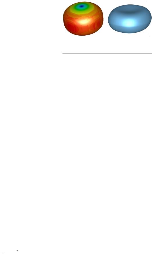
Fig. 1. Surface currents for the fundamental mode in a super-ellipsoid resonator and an example of a depressed super-ellipsoid.
B. The Rectangular Waveguide Filter
The rectangular waveguide filter was chosen to study as it is probably the most common realization of wave- guide filter. They are usually realized with shunt-inductive irises although inductive posts are also popular as they are simple to manufacture. For the resonator, the larger is the b -dimension, the greater the Q, but at the expense of higher order mode suppression. The a-dimension has an optimum for Q when a-dim is equal to the cavity length but this is not optimal for the fundamental mode repeat passband, a larger a-dim giving wider band rejection.
It is possible to increase theQ of a cuboid cavity by intro- ducing radii on the edges. Blending in the E-plane or trans- verse-plane produces the greatest improvement with H-plane blendingbeinglessimportant.Thisshouldbeevidentwhenthe surface currents within a cuboid resonator or filter are studied.
III. COMPLEX GEOMETRIES FOR PERFORMANCE ENHANCEMENT
A. Ellipsoid Cavity
The ellipsoid cavity is an interesting shape to analyze. For such a resonator, a simulated Q of 6400 compares favora- bly with a Q of 5400 for a standalone rectangular waveguide resonator. In addition, the second eigenmode resonance is higher. Comparisons are based on a rectangular resonator using WR75 resonating at 12.875 GHz.
With this resonator, a number of filters were modeled. It became apparent that it was difficult to achieve sufficient coupling. The coupling structures were large which had a det- rimental effect on the filter higher order mode rejection and the overall Q. By allowing the ellipsoids to intersect, the cou- pling structures were reduced in size. This gave an improve- ment in rejection but Q was affected.
B. Super-Ellipsoid Cavity
The improved Q and second eigenmode resonance of the ellipsoid cavity over a cuboid led to the investigation of the super-ellipsoid. The generalized super-ellipsoid is defined by
(|Ax |
|
|
y r |
) |
t |
|
|
| |
r |
r |
t |
|
|||
|
+ |__B| |
+ |Cz | |
|
(1) |
where A, B, and C are scaling factors in each axis and t and r control the flattening or alternatively squareness.
Compared to the ellipsoid, the super-ellipsoid cavity had lower Q for the same higher order eigenmode resonances. However, it is much more amenable for use in a filter allow- ing the coupling structures to be of a more compact size without the need for cavity intersection. This improved the overall filter Q for a given far-out-of band response.
C. Depressed Super-Ellipsoid Cavity
It may be seen from Fig. 1 that the surface currents of the fundamental mode in a super-ellipsoid cavity are at a mini- mum in the center of the resonator. A depression in this area lowers the resonant frequency. If the resonator dimensions are adjusted to recover the original resonant frequency then the higher order resonances increase in frequency. The depression may be created by a simple cosine envelope function to the appropriate axes of the super-ellipsoid.
A parametric study of the resonator was performed to determinetheimprovementinQ andbandwidth.Asanexam- ple it was possible to achieve a 13% improvement in Q and 27% increase in the second eigenmode frequency compared to a cuboid resonator. Of course, it is possible to increase the Q at the expense of reduced bandwidth andvice versa.
D. Elliptic Iris With Hyperbolic Taper
From the studies on the rectangular waveguide filter, the circular iris showed the best performance in terms of bothQ andout-of-bandrejection.However,thereislimitedcoupling bandwidth from a circular iris before it becomes truncated by the waveguide it sits in. This may be overcome by using an elliptic iris in the cases when truncation would occur.
Tapering or rounding of irises in thez-direction (direction of propagation) also helps to improve the Q. This is due to the high surface currents at the edges of the iris which are more evenly distributed when the iris edge is curved rather than sharp. A simple radius blend of the edge is effective in reduc- ing the surface currents. The same radius on each edge of the iris is best for all internal irises. For the input/output iris, it is advantageous to have a larger radius on the cavity side than the external side but the effect is minimal. One effect observed is
2 PROCEEDINGS OF THE IEEE

This article has been accepted for inclusion in a future issue of this journal. Content is final as presented, with the exception of pagination.
Booth and Valles Lluch: Enhancing the Performance of Waveguide Filters
Fig. 2. Cross section through hyperbolic blended elliptic iris.
that there is an ideal thickness for an iris which depends on the frequency and coupling value required. However, thicker irises lead to greater deviation in the filter response when com- pared to one modeled using a frequency-invariant normalized susceptance. Of course, this may be exploited in certain cir- cumstances. Inductive irises gave less rejection above band and morerejectionbelowbandthethickertheiris.Capacitiveirises produce the opposite effect. An elliptic iris could produce close to a frequency-invariant normalized susceptance.
More complex tapering such as elliptic or hyperbolic has little benefit for a rectangular waveguide filter. However, the hyperbolic taper produces a much better blend into a superellipsoid resonator. An example may be seen in Fig. 2.
I V. THIRD-ORDER FILTER
Asatrialofboththeshapingandthemanufacturingprocess,
athird-order filter was designed. There were no require- ments set other than a center frequency of 12.875 GHz and
adesign bandwidth of 250 MHz. This would allow com- parison against the baseline rectangular filter. The resonator cavities were depressed super-ellipsoids with the coupling achieved using circular/elliptic cross-section irises; a circu- lar cross section was preferred but had to be changed to an elliptic cross section for the input and output iris in order to
Fig. 4. View of the third-order filter.
achieve sufficient coupling. The irises had hyperbolic shap- ing to blend into the cavities. The filter internal volume may be seen in Fig. 3.
The filterwasmanufactured usingselective lasermelting (SLM) of Scalmalloy powder, a proprietary aluminium alloy. The flanges were machined flat and drilled before the com- ponent was plated using a standard electrolytic process. An endviewofthefiltermaybeseeninFig.4.Itmaybeobserved that the iris is slightly misshapen. This was expected as the area in question is on the downside of the build which has the least support for the surface. It should be noted that no internal support structures were used during the build.
The unit was measured for radio-frequency (RF) perfor- mance and the results are given in Fig. 5. It may be seen
Fig. 3. CST model of the third-order filter.
Fig. 5. Measured performance of the third-order filter versus theory.
PROCEEDINGS OF THE IEEE 3

This article has been accepted for inclusion in a future issue of this journal. Content is final as presented, with the exception of pagination.
Booth and Valles Lluch: Enhancing the Performance of Waveguide Filters
that there is a slight shift in the center frequency of 25 MHz and reduction in bandwidth of about 10 MHz. There was no tuning performed on the unit. From the measurements, the filter Q was calculated as 4300. This is comparable to a conventional rectangular waveguide filter Q of 4400. This is a good indication that the shaping has compensated for the increased surface roughness of SLM compared to mill- ing. The CST Microwave Studio frequency domain solver was used to simulate performance with a conductivity of 3 ≈ 107 S/m for consistency with the earlier studies. Q from measurements was calculated using the group delay- insertion loss method.
V. FIFTH-ORDER FILTER
A. Breadboard
Aspartofthedevelopmentofaflightfilter,abreadboard was developed to demonstrate the design and manufactur- ing principles. The filter was intended as a drop-in replace- ment for an existing rectangular waveguide filter. The key requirements are given in Table 1. A study was performed to determine if the filter could be realized purely as a band- pass filter. The study concluded that in terms of loss it was better to use a bandpass/low-pass combination if rejection above 30 GHz was required. The simulated performance of the bandpass providing rejection up to 30 GHz is shown in Fig. 6. There is good suppression of all modes up to 30 GHz. To achieve this, the resonator was reduced in size with a sig- nificant depression in the center of the super-ellipsoid. This gave a simulated Q of 2900 for the filter using 3 ≈ 107 S/m conductivity. This equates to an in-band loss of 0.31 dB for this realization which is the same as for a bandpass/lowpass combination giving rejection to 40 GHz. However, the shaped filter is much more compact than the standard reali- zation which is important in many situations.
The coupling structures were also updated compared to the third-order filter. A hyperbolic taper was used but with different parameters for the x- and ydirection.- This gave a better blend of the iris to resonator junction and allowed an increased ysubaxis of the elliptic cross section. This meant that all irises in the filter could be circular cross section with the exception of the input/output irises. A slight increase in
Fig. 6. Simulated performance of the shaped bandpass filter showing rejection of all higher order modes up to 30 GHz.
bothoverallQ andhigherordermoderejectionwasobserved in the electrical model.
The filter was manufactured using SLM and plated. A modeloftheunit’sinternalvolumeandapictureoftheactual filter may be seen in Fig. 7. The unit was then measured and results may be seen in Fig. 8. Insertion loss shows a slight increase compared to theory but some of the increased loss at the edge of band is due to a slightly degraded return loss. The return loss was compliant over the required passband. From the measurements, the filter Q was calculated as 4600
Table 1 Initial Filter Key Requirements
Fig. 7. CST model of breadboard filter internal volume and end view of the manufactured filter.
4 PROCEEDINGS OF THE IEEE

This article has been accepted for inclusion in a future issue of this journal. Content is final as presented, with the exception of pagination.
Booth and Valles Lluch: Enhancing the Performance of Waveguide Filters
Fig. 10. Measured performance of the flight filter.
Fig. 8. Measured performance of the breadboard filter versus theory.
which is an improvement compared to a conventional rec- tangular waveguide filter.
B. Flight Filter for a Satellite Payload
The success of the breadboard and the change of some key requirements lead to a minor redesign of the bandpass filter.Amajorchangetotherejectionrequirementsreplaced the need for rejection up to 40 GHz to only 22 GHz. This allowed a simple bandpass design without the need for a low-pass filter. To ensure good rejection of all modes up to 22 GHz, the cavity depression was increased leading to shorter resonators. This moved the start of the TE10 repeat
Fig. 9. Image generated from CT scan of the qualification filter.
passbandto24GHzwithothermodessuppressedto23GHz. The center frequency and bandwidth were also adjusted to provide more rejection margin.
As the flight filter is a drop-in replacement, it was neces- sary to include extra lengths of waveguide at the input and output. While this means that the filter is heavier than it needs to be, the decision was taken not to attempt a signifi- cant mass reduction exercise. This allowed a much simpler route to flight qualification as there are greater stress and fatigue margins. Even so, the filter weighed less than 60 g, i.e., half the requirement. This is of particular importance for satellite payloads. Although the filter is fifth order, the built length is about the same as for a ninth-order filter.
The filter flanges were machined prior to silver plating. The unit then underwent a proto-flight test regime that included vibration and thermal cycling. A qualification unit built at the same time followed an identical manufactur- ing process but was then subject to more demanding vibra- tion and thermal cycling as well as mechanical and thermal shock. An X-ray scan was performed on the qualification unit and a computed tomography view of the interior may be seen in Fig. 9. Both units were measured extensively and the results of the flight filter may be seen in Fig. 10. The fil- ters met the requirements with significant margin.
V I. THE SUITABILITY OF THE MANUFACTURING PROCESS AND HOW SHAPING MAY HELP
There have been a number of filter designs reported that use SLM. Many of these have poor performance compared to that expected using conventional manufacturing techniques.
PROCEEDINGS OF THE IEEE 5
This article has been accepted for inclusion in a future issue of this journal. Content is final as presented, with the exception of pagination.
Booth and Valles Lluch: Enhancing the Performance of Waveguide Filters
Higher loss, poor return loss, and significant shifts in center frequency and bandwidth compared to predictions are often seen such as in [1], [6], and [7]. However, careful choice of topology, as reported in [8], can help.
Surface roughness is much worse than for convention- ally machined components. However, from our experience, it appears that loss is not affected as much as would be expected. There could be a number of reasons for this. Most of the work on increase in surface resistivity with roughness was performed using milled or extruded components. The roughness tends to have very sharp peaks and troughs due to the manufacturing process. SLM uses a powder whose grains tend to be spherical. It is postulated that when the grains are fused, the surface has more rounded peaks and troughs compared to conventionally manufactured compo- nents. This could form an easier path for the currents with less localized concentration. Also, during the build, there is a downward facing side within the cavity that will be rougher than the upper facing sides. This is the reason for the slightly misshapen irises evident in Figs. 3 and 7. If this rough surface is where there are significant surface currents, then loss will be affected. The orientation of the component during the build can therefore have an impact on loss. Shap- ing of the filter can overcome the increased loss associated with the roughness.
Accuracy of the build determines how well the final fil- ter performs. The laser used to melt the powder can be con- trolled very accurately which means that the build accuracy is determined by other factors. A layer is typically 20 μ m so there is a limit to feature size. However, more important is how well characterized the shrinkage of the build is. The build takes place in an inert atmosphere at elevated temper- atures. There will also be a number of supports around the build that are removed later. When the part is brought back to ambient temperature and support removed, some inbuilt
stress can cause the component to change shape slightly. Relatively large flat areas can be affected by this the most. The more organic form of the shaped filter appears to be less affected by this. Bridging of areas can also occur which is where two surfaces meet. There can be very poor definition in these areas which will also affect filter performance. The shaped filter has fewer of these areas, and they can easily be minimized by choosing the correct build orientation.
V II. CONCLUSION
The work presented demonstrates that additive manufac- turing using SLM can produce RF components that have performance benefits compared to conventionally manufac- tured components. Shaping of the cavities and irises allows the design to overcome the effects on insertion loss of the process and can have a beneficial effect on out-of-band per- formance. The results of filters manufactured by AM show good agreement with predictions and a satellite flight filter was developed and qualified. The manufacturing process has also been discussed and thoughts on how the chosen geometries help have been presented.
Future work will be focused on more complex filters and diplexers along with more integration of components. More shapes may be investigated to further enhance performance.
Acknowledgment
The authors would like to thank C. Ernst, C. M. España, and P. M. Iglesias of ESTEC for their support and technical assistance. They would also like to thank J. Meyer at Airbus Group Innovations for providing useful input and discussion regarding manufacturing.
REFERENCES
[1]J. A. Lorenteet al., “Single part microwave filters made from selective laser melting,” in Proc. Eur. Microw. Conf., Sep. 2009,
pp. 1421–1424.
[2]P. Booth and E. V. Lluch, “Performance enhancement for waveguide filters using addi- tive manufacturing,” in Proc. Int. Workshop Microw., Toulouse, France, 2015.
[3]P. Booth, M. Skeen, and S. Stirland, “Low cost, short lead-time feed chain components for multi-beam antennas,” in Proc. Eur. Conf.
Antennas Propag., Berlin, Germany, Mar. 2009,
pp. 853–857.
[4]J. A. Lorente, C. Ernst, and A. A. Melcon, “Rig- orous derivation of lossy equivalent circuit for narrowband waveguide direct-coupled-cavity filters,” IET Microw. Antennas Propag., vol. 7, no. 4, pp. 251–258, Mar. 2013.
[5]J. A. Lorente,“Techniques for loss reduction in waveguide filters,” Ph.D. dissertation, Poly- techn. Univ. Cartagena, Cartagena, Spain, 2013.
[6]B. Zhang and H. Zirath, “3D printed iris bandpass filters for millimetre-wave applica-
tions,” IET Electron. Lett., vol. 51, no. 22,
pp. 1791–1793, 2015.
[7]V. T. di Crestvolant, P. M. Iglesias, and M. J. Lancaster, “Advances in manufacturing of 4 × 4butler matrices with inherent bandpass filter functions,” in Proc. Int. Workshop Microw., Toulouse, France, 2015.
[8]O. S. Peveriniet al., “Additive manufacturing of Ku/K band waveguide filters for space applications,” inProc. Int. Workshop Microw., Toulouse, France, Mar. 2015.
6 PROCEEDINGS OF THE IEEE
This article has been accepted for inclusion in a future issue of this journal. Content is final as presented, with the exception of pagination.
Booth and Valles Lluch: Enhancing the Performance of Waveguide Filters
ABOUT THE AUTHORS
Paul Booth received the B.Eng. degree in electrical engineering from the University of Leeds, Leeds, U.K., in 1987.
From 1987 to 1994, he worked at BAe Space Systems on LNAs, SSPAs, filters, and multiplexers. From 1994 to 1995, he worked for Phase Devices Ltd. on mobile base station filters and diplexers. From 1995 to 1998, he worked at Matra Marconi Space as Responsible Engineer on a number of filters and multiplexers. In 1998, he moved to Ericsson Radio Access, Stockholm, Sweden, where he was responsible for the design of mobile communication passive RF equipment. Since 2003, he has been at Airbus Defence and Space, Stevenage, U.K., where he is currently working in the Antenna Group. His research interests include filter design, modeling and realization, high-power phenomena, and novel manufacturing techniques.
Mr. Booth is a member of the Institution of Engineering and Technology (IET). He was a recipient of the EuCAP Best Antenna Oral Paper Prize in 2009.
Elena Valles Lluch received the telecommunications engineering degree from Universidad Polit cnica de Valencia (UPV), Valencia, Spain, in 2007.
From 2007 to 2013, she was an Electrical Engineer at the Space Division, RYMSA, Madrid, Spain. During this period, she developed specialization in filters and high-power phenomena. Since 2013, she has been an RF Feeds and Filters Engineer in the Antenna Group, Airbus Defence and Space, Stevenage, U.K. Her research interests are filter and antenna electromagnetic design, advanced manufacturing techniques, and high-power phenomena.
PROCEEDINGS OF THE IEEE 7