

диафрагмированные волноводные фильтры / f5b93fed-84b4-46f6-a3e2-04f229db45b2
.pdfThis article has been accepted for inclusion in a future issue of this journal. Content is final as presented, with the exception of pagination.
IEEE TRANSACTIONS ON MICROWAVE THEORY AND TECHNIQUES |
1 |
Design Methodology of a Tunable Waveguide Filter With a Constant Absolute Bandwidth Using
a Single Tuning Element
Gowrish Basavarajappa , Graduate Student Member, IEEE, and Raafat R. Mansour, Fellow, IEEE
Abstract— This paper presents a novel configuration for a high-Q tunable waveguide (WG) filter with a constant absolute bandwidth (BW). The key feature of this filter is that it is tuned by a single tuning element. This paper investigates the theory of coupling behavior of single septum and double septa to achieve constant absolute BW. The theory is presented for both the coupling matrix-based and inverter-based filter topologies. The filter design methodology is lucidly presented covering the design strategy adopted for interresonator coupling, input–output coupling and tuning element. The tuning mechanism of the proposed filter is explained with measurement results presented for a K u-band tunable WG filter designed at 15 GHz with a 2% BW to achieve 15% tuning range. The filter promises to be useful in emerging 5G millimeter-wave applications, where the filter size is very small to accommodate many mechanical tuning elements. Furthermore, the proposed design methodology is scalable, i.e., the tuning mechanism is independent of the filter order.
Index Terms— High- Q, tunable filter, waveguide (WG) filter.
I. INTRODUCTION
TUNABLE filters are vital components in frequency reconfigurable (or frequency agile) communication systems, which facilitate effective utilization of allotted frequency spectrum [1]. Furthermore, frequency reconfigurable systems can be potentially a cost-effective solution for wireless base stations as well for emerging satellite and aerospace applications [2], [3]. One of the important requirements for tunable filters in such applications is to maintain a constant absolute bandwidth (BW) over the tuning range. This is essential in order to achieve a constant data rate over the tuning range. In addition, almost all of the communication system applications require maintaining a certain out-of-band rejection, which can be achieved if the absolute BW of the filter remains constant over the tuning range. Thus, by maintaining a constant absolute BW over the tuning range, the achievable data rate and the filter isolation requirements remain the same over the entire tuning range, which is highly desirable. Hence, one of the focus areas in microwave filter design is to design and develop high-Q (Quality factor) tunable filters with a
constant absolute BW over the tuning range [4], [5].
Manuscript received May 2, 2018; revised August 27, 2018; accepted September 19, 2018. This paper is an expanded version from the 2018 International Microwave Conference, Philadelphia, PA, USA, June 10–15, 2018.
(Corresponding author: Gowrish Basavarajappa.)
The authors are with the Electrical and Computer Engineering Department, University of Waterloo, ON N2L 3G1, Canada (e-mail: gowrish.biit@gmail.com; rrmansour@uwaterloo.ca).
Color versions of one or more of the figures in this paper are available online at http://ieeexplore.ieee.org.
Digital Object Identifier 10.1109/TMTT.2018.2873383
This has led to significant research in recent years in developing high-Q tunable filters, typically focused on MEMS-based and motor-based tunability [4], [5]. References [6] and [7] have addressed the design of high-Q tunable dielectric resonator filters at Ku-band using MEMS actuation. MEMS-based high-Q tunable filters at C- and at K -bands have also been developed [8]–[10]. MEMS-based tunable filters have an inherent advantage of being compact; however, they have lower Q compared to filters tuned using motors. An attempt to improve Q using a combination of MEMS and piezomotors is reported at S-band to minimize the insertion loss (IL) [11]. It should be noted predominantly that filters reported in the literature employ tuning elements at least equal to the number of resonators.
The objective here is to design a high-Q tunable filter with a constant absolute BW using only one tuning element. In general, any filter of order “N” can be readily tuned for a constant absolute BW using “2N + 1” independent tuning elements. Over the past years, significant research has resulted in reducing the number of tuning elements [4]–[11] to 50% by using tuning elements only for N-resonators. However, with the emerging 5G millimeter-wave applications, it is quite challenging to accommodate “N” tuning elements, especially in high-order high-Q filters. Furthermore, the complexity of the control mechanism for tuning elements also increases with the filter order.
In this paper, an effort is made to address this important emerging challenge, by proposing a waveguide (WG) filter that can be tuned using a single tuning element only. A brief description of the concept has been recently presented in [12]. In this paper, we present the details of the theory of interresonator (IR) and input–output (IO) couplings to achieve constant absolute BW using both coupling matrix (CM)- based topologies and inverter-based topologies. This paper investigates the coupling behavior of both the single septum and double septa over the tuning range, describing the design methodology adopted to realize a constant absolute BW over the tuning range with only one tuning element. The tuning mechanism is explained with measurement results presented for a Ku-band tunable WG filter designed with a 2% BW to achieve 15% tuning range.
II. THEORY FOR CONSTANT ABSOLUTE BW
The IR and IO couplings play a vital role in designing filters with a constant absolute BW. In this section, theoretical requirements for the same are explored in detail for both
0018-9480 © 2018 IEEE. Personal use is permitted, but republication/redistribution requires IEEE permission. See http://www.ieee.org/publications_standards/publications/rights/index.html for more information.
This article has been accepted for inclusion in a future issue of this journal. Content is final as presented, with the exception of pagination.
2 |
IEEE TRANSACTIONS ON MICROWAVE THEORY AND TECHNIQUES |
the types of filter topologies, namely, CM-based and inverterbased topologies.
A. Coupling Matrix-Based Filter Topology
In this topology, the entire filter design can be divided into two major steps, namely, the IR coupling and IO coupling. The following equations relate the physical couplings to the normalized couplings [13]:
|
|
ki j × fr = Mi j × BW |
(1) |
|
|
|
τs11_max = 4/(2π ×BW × Ms21) |
(2) |
|
where ki j |
is |
the |
physical coupling coefficient |
between the |
resonators, |
fr |
is |
the center frequency, Mi j is |
the normal- |
ized coupling coefficient between the resonators, BW is the absolute BW, Ms1 is the normalized coupling coefficient at IO, and τs11_max is the peak IO reflection group delay. The normalized coupling coefficients (Mi j and Ms1) depend only on the filter type and its order and not on the center frequency and BW. As a result, the key requirements to design a filter with a constant absolute BW are: 1) a constant peak IO reflection group delay (τs11_max) with respect to fr (center frequency) over the tuning range and 2) a constant ki j × fr product over the tuning range. Similar observations have been made in [14].
B. Inverter-Based Filter Topology
In this topology, the filter design involves designing appropriate impedance (or admittance) inverters between the resonators. The following equations relate the impedance inverter to the normalized filter coefficients:
|
|
Kn,n+1 |
fr |
= |
|
|
π BW |
(3) |
||||||||
|
|
Z0 |
|
|
|
|
2√ |
|
|
|
||||||
|
|
|
|
|
|
gn gn+1 |
|
|||||||||
|
|
β × ln = π + 0.5 × (φn + φn+1) |
(4) |
|||||||||||||
|
|
|
|
|
|
|
|
|
|
|
|
|
|
|||
|
|
K0,1 |
|
|
|
|
|
= |
|
|
π BW |
|
(5) |
|||
|
|
f |
r |
|
||||||||||||
|
|
|
|
|
2g0g1 |
|||||||||||
|
|
Z0 |
|
|
|
|
|
|
|
|||||||
where |
Kn,n+1 is the value of impedance inverter, fr is |
the |
||||||||||||||
center |
frequency, |
β |
|
|
is |
the propagation phase constant |
of |
|||||||||
the WG at center frequency, gn is the normalized low-pass g-values, φn is the phase contribution from the impedance inverter in degrees, BW is the absolute BW, and Z0 is the characteristic impedance of the WG. The normalized low-pass g-values, (i.e., gn) depend only on filter type and its order, and hence, they are independent on center frequency and BW. As a result, from the model based on impedance inverter, the key requirements to design a filter with a constant absolute BW are follows.
1)A constant (Kn,n+1/Z0) × fr product over the tuning range for IR coupling.
2)A constant (K0,1/Z0)( fr )0.5 product over the tuning range for IO coupling.
3)A constant phase contribution (φn) from the impedance inverter over the tuning range.
To the best of the authors’ knowledge, these observations on inverter-based filter topology are being reported for the first time. It is worth mentioning here that the requirement for IO coupling is not the same as that for IR coupling.
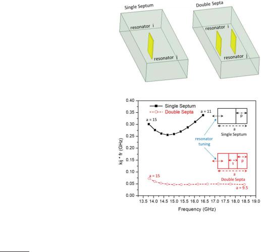
Fig. 1. Schematic: single septum and double septa coupling.
Fig. 2. CM-based filter topology: single septum and double septa coupling.
III. COUPLING BEHAVIOR: E-PLANE
METALLIC SEPTUM
The E-plane metal septum filter is widely used in aerospace applications due to its superior performance like low IL, highpower handling capacity, and higher fabrication yield [15]. Interestingly, the E-plane metal septum also offers superior electrical performance in designing tunable filters, as will be discussed in this section. Furthermore, the E-plane septum is physically isolated from the tuning element, and hence, it significantly simplifies the tuning mechanism.
Fig. 1 shows a schematic of two WG resonators coupled by a single septum and double septa. As the resonator frequency is tuned, ANSYS HFSS is used to extract coupling and inverter values from 3-D structure [13]. Fig. 2 depicts the ki j × fr product for the single septum and double septa over the tuning range. The resonance frequency is tuned by varying the width of the cavity, i.e., “a” dimension as shown in Fig. 2. It can be observed that the double septa have a significantly wider tuning range, where ki j × fr product is constant.
Fig. 3 depicts the impedance inverter values and the corresponding phase contribution of the single septum and double septa. It can be observed that double septa offer wider tuning range over which (Kn,n+1/Z0) × fr product is constant. The observation becomes even more convincing from phase contribution (φn) plot, where double septa have nearly the same phase contribution over the tuning range. It can be seen that the impact of phase loading (φn) of the septa on the adjacent resonator remains constant over a wider tuning range if double septa are employed for the coupling.

This article has been accepted for inclusion in a future issue of this journal. Content is final as presented, with the exception of pagination.
BASAVARAJAPPA AND MANSOUR: DESIGN METHODOLOGY OF A TUNABLE WG FILTER |
3 |
Fig. 5. Assembly view of the proposed tunable WG filter.
Fig. 3. Impedance inverter-based filter topology for IR coupling: single septum ( p = 7.4 mm) and double septa coupling ( p = 3.75 mm and s = 5 mm).
Fig. 6. 3-D schematic of the proposed tunable WG filter.
Fig. 4. IO coupling: single septum and double septa coupling.
dimensions of “a = 13 mm” and “b = 6.5 mm”. It consists of two body halves, two septa, and a spacer. The IO couplings to the filters are realized using coaxial probes. The filter is tuned using a metal insert moving inside one of the body halves. Fig. 6 depicts the internal 3-D schematic of the filter.
Double septa offer wider tuning range than single septum for IO coupling as well, as depicted in Fig. 4. The (K0,1/Z0)× ( fr )0.5 value for double septa is constant over a wider tuning range than that of single septum. The phase contribution (φn) is not shown to avoid duplication.
The double septa offer wider tuning range compared to single septum, since it has additional degrees of freedom. The single septum coupling structure has only two variables: width and position of the septum, whereas the double septa have three variables: width, position, and spacing between the septa. This provides flexibility in optimizing the structure to realize the coupling behavior shown in Fig 2. It is worth mentioning here that following a similar argument, metallic septa higher than two are expected to provide further wider tuning range.
IV. DESIGN METHODOLOGY: A HIGH-Q TUNABLE
FILTER WITH SINGLE TUNING ELEMENT
A fifth-order Chebyshev all-pole filter is designed for the proof of the proposed concept. The filter is designed at 15 GHz with a fraction BW of 2%. Fig. 5 depicts the assembly view of the proposed tunable WG double septum filter with WG
A. InterResonator Coupling
The IR coupling is implemented using the E-plane double metal septa owing to its superior performance for realizing tunable filters as explored in Section III. The double septabased coupling has 3 degrees of freedom to realize the required constant ki j × fr product over the tuning range, namely, “s” (spacing between the septum), “ p” (position within the WG), and “w” (septum width). It is observed that the width of the septa determines the coupling value, whereas position and spacing determine the tuning range. Fig. 7 depicts the impact of position and spacing on the tuning range. Thus, the design of IR coupling is performed in two sequential steps. To start with, suitable values of position and spacing of the double septa are searched to maximize the tuning range over the band of interest. Once the position and spacing are finalized (s = 5 mm and p = 3.75 mm for the particular design), the width of septa are determined based on the desired coupling values of the filter. Fig. 8 depicts the flowchart adopted to realize IR coupling. From Fig. 9, it can be observed that the ki j × fr product is nearly constant from 14.7 to

This article has been accepted for inclusion in a future issue of this journal. Content is final as presented, with the exception of pagination.
4
Fig. 7. IR coupling using double septa: “s” and “ p” effect on tuning range.
Fig. 8. Flowchart of IR coupling design for constant absolute bandwidth.
17.7 GHz. The desired ki j × fr values are 0.2596 GHz (M12 and M45) and 0.1907 GHz (M23 and M34).
B. Input–Output Coupling
The IO coupling is realized using a SubMiniature version A (SMA) probe. Alternatively, double septa can also be used for IO coupling as discussed in Fig. 4. However, in such a case, the transition from fixed WG adaptor to the movable sidewall in the filter needs to be considered. In the proposed design, the SMA probe is used for its simplicity. In addition, the SMA probe coupled filter is compact. Fig. 10 depicts the peak group delay, which is nearly constant from 14.6 to 16.6 GHz. From the model of the filter shown in Fig. 6, it can be observed that IO coupling has 3 degrees of freedom:
“ p_len” (pin |
length), “d_z” (distance from shorting wall), |
and “ p_pin” |
(position within the WG). It is observed that |
pin length determines the IO coupling value whereas distance
IEEE TRANSACTIONS ON MICROWAVE THEORY AND TECHNIQUES
Fig. 9. IR coupling with constant ki j × fr product over the tuning range with s = 5 mm and p = 3.75 mm.
Fig. 10. IO coupling with constant peak group delay with respect to fr .
(“d_z”) and position (“ p_pin”) determine the tuning range. To start with, the distance and position are tuned to maximize the tuning range, following which the pin length is altered to obtain the required IO coupling. Fig. 11 depicts the flowchart adopted to realize IO coupling. It is interesting to observe from Figs. 8 and 11 that the design of IR and IO couplings can be completely automated using powerful 3-D electromagnetic simulators, such as HFSS, which also provide interface for programing tools.
C. Tuning Mechanism
Tunability of the filter is achieved by moving the sidewall of the WG filter, i.e., by changing the “a” dimension. In the proposed filter, this is achieved by linearly moving the patterned single-metal insert in the proximity of one of the septa as shown in Fig. 5. The metal insert is designed to have a gap of 0.25 mm on both the sides (top and bottom) to facilitate friction-free movement.
The shape of the metal insert tuning element is selected to eliminate undesired modes (gap resonances) resulting from having a gap between the metal insert and the WG wall. Fig. 12 shows the undesired gap resonance generated when the movable metal insert has no pattern. It can be observed from Fig. 13 that suitable patterning of movable metal insert helps to eliminate these modes from the band of interest. Two support rods are used to minimize the skewing of the metal insert tuning element within the WG. A single motor is used to drive the two supporting rods. It is worth mentioning here that the

This article has been accepted for inclusion in a future issue of this journal. Content is final as presented, with the exception of pagination.
BASAVARAJAPPA AND MANSOUR: DESIGN METHODOLOGY OF A TUNABLE WG FILTER
Fig. 13.
Fig. 11. Flowchart of IO coupling design for constant absolute BW.
Fig. 14.
5
Movable metal insert with pattern: undesired mode at 21.1 GHz.
EM-Simulated transmission coefficient (S21) of the tunable filter.
Fig. 12. Movable metal insert without pattern: undesired mode at 12.2 GHz.
shape of the metal insert tuning element provides additional degrees of freedom, especially for the IO coupling where the coupling requirements are different from that of IR coupling.
Figs. 14 and 15 depict the EM-simulated response of the proposed tunable filter obtained by varying the position of the metal insert tuning element. Fig. 16 illustrates the variation of BW and IL over the tuning range. BW variation is observed to be within 10% while the center frequency is tuned from 14.65 to 17.15 GHz, corresponding to the tuning range of 15.7%. The IL of the filter is around 0.3 dB over the entire tuning range. The philosophy adopted in this paper is rapid prototyping for the proof of concept. Certainly, the filter return loss can be improved by rigorous optimization of the parameters “s”, “ p”, and “w”. The simulated unloaded quality factor of the resonator is around 5000–15 GHz.
V. MEASUREMENT AND DISCUSSION
Fig. 17 shows a photograph of a prototype unit developed as a proof of concept. The photograph in Fig. 18 shows the
Fig. 15. EM-Simulated reflection coefficient (S11) of the tunable filter.
individual WG components of the filter prior to assembly. Copper is used for the two WG halves, two septa, and for the tuning element. The IO resonators are realized using a single metallic piece. Aluminum rather than copper is used for these single metallic pieces since it is easier to minimize the corner radius during machining. Support rods have been built with a provision to be moved inside one of the WG halves

This article has been accepted for inclusion in a future issue of this journal. Content is final as presented, with the exception of pagination.
6 |
IEEE TRANSACTIONS ON MICROWAVE THEORY AND TECHNIQUES |
Fig. 16. EM-Simulated BW and IL variation over the tuning range.
Fig. 19. Motor-based tuning station with the proposed tunable filter.
Fig. 17. Photograph of the fabricated prototype unit: assembled.
Fig. 20. Measured transmission coefficient (S21) of the tunable filter.
Fig. 18. Photograph of the fabricated prototype unit: individual waveguide components.
Fig. 21. Measured reflection coefficient (S11) of the tunable filter.
(fixed side wall-2) using a single motor. Fig. 19 shows the photograph of the motor-based tuning station. The mechanism allows changing the penetration of the metal insert inside the filter with micrometer resolution. It should be noted that the tuning station shown in Fig. 19 employs only one motor. It is built as a generic tuning station for testing prototype tunable filters of any size. The unit is interfaced to a computer that controls the vertical movement with steps of few microns
to allow for continuous tuning. In the actual applications, a similar miniature mechanism can be connected directly to the metal insert and integrated with the filter housing to realize an overall compact tunable filter.
Figs. 20 and 21 depict the measured response of the filter. Tuning range of the filter is 1.4 GHz (from 14.8 to 16.2 GHz), where the BW variation is within 5%. The measured variations

This article has been accepted for inclusion in a future issue of this journal. Content is final as presented, with the exception of pagination.
BASAVARAJAPPA AND MANSOUR: DESIGN METHODOLOGY OF A TUNABLE WG FILTER |
7 |
Fig. 22. Measured BW and IL variation over the tuning range.
deviations from the simulated response, it is, indeed, very promising as a proof of concept. Furthermore, the methodology used for the design of the proposed tunable filter is easily scalable, i.e., the tuning mechanism is independent of the order of filter. This is one of the key features of the proposed tunable filter.
VI. CONCLUSION
This paper has presented a novel configuration for a high- Q tunable WG filter with a constant absolute BW. The key feature of this filter is that it is tuned by a single tuning element. The variation of the IO coupling and IR coupling of the single septum and double septa filters with filter center frequency has been investigated using both CMbased and inverter-based topologies. The analysis has revealed that double septa with optimized dimensions are optimum to realize a constant absolute BW over a relatively wide tuning range. A detailed design methodology has been presented for proper selection of the optimum offset dimensions of the double septa. An investigation of the shape of the metal insert tuning element on the filter spurious performance has been also presented. Measured results are presented for a Ku-band tunable filter achieving a constant absolute BW over a tuning range of 15%. The filter promises to be useful in emerging 5G millimeter-wave applications where the filter size is very small to accommodate many mechanical tuning elements.
Fig. 23. Measured group delay response of the tunable filter at 15.6 GHz.
ACKNOWLEDGMENT
Fig. 24. Wide span response of the tunable filter at 15.6 GHz: measured and simulated.
of BW and IL over the tuning range are shown in Fig. 22. The increase in the measured IL of around 0.6 dB is attributed predominantly to the fact that the first and last cavities are made of aluminum and to the use of stainless steel rods that hold the metal insert tuning element in this initial prototype. Silver plating the whole filter including the support rods will certainly help in improving the IL of the filter. The group delay response and spurious performance of the filter are shown in Figs. 23 and 24, respectively.
The filter has |
a spurious free response up to 20 GHz. |
It is important to |
note that though the prototype has some |
The authors would like to thank K. Janzen, M. Kuntz, and R. Forgett, Engineering Machine Shop, University of Waterloo, Waterloo, ON, Canada, for their assistance in fabricating the prototype unit.
REFERENCES
[1]H. Arslan, Cognitive Radio, Software Defined Radio, and Adaptive Wireless Systems. Dordrecht, The Netherlands: Springer, 2007.
[2]R. R. Mansour, “High-Q tunable dielectric resonator filters,” IEEE Microw. Mag., vol. 10, no. 6, pp. 84–98, Oct. 2009.
[3]C. Miller, “How and why commercial high-capacity satellites offer superior performance and survivability in the future space threat,” in Proc. 32nd Space Symp., Colorado Springs, CO, USA, Apr. 2016, pp. 1–12.
[4]R. R. Mansour, F. Huang, S. Fouladi, W. D. Yan, and M. Nasr, “High-Q tunable filters: Challenges and potential,” IEEE Microw. Mag., vol. 15, no. 5, pp. 70–82, Jul./Aug. 2014.
[5]D. Peroulis, E. Naglich, M. Sinani, and M. Hickle, “Tuned to resonance: Transfer-function-adaptive filters in evanescent-mode cavityresonator technology,” IEEE Microw. Mag., vol. 15, no. 5, pp. 55–69, Jul./Aug. 2014.
[6]W. D. Yan and R. R. Mansour, “Tunable dielectric resonator bandpass filter with embedded MEMS tuning elements,” IEEE Trans. Microw. Theory Techn., vol. 55, no. 1, pp. 154–160, Jan. 2007.
[7]F. Huang, S. Fouladi, and R. R. Mansour, “High-Q tunable dielectric resonator filters using MEMS technology,” IEEE Trans. Microw. Theory Techn., vol. 59, no. 12, pp. 3401–3409, Dec. 2011.
[8]X. Liu, L. P. B. Katehi, W. J. Chappell, and D. Peroulis, “A 3.4–6.2 GHz continuously tunable electrostatic MEMS resonator with quality factor of 460–530,” in IEEE MTT-S Int. Microw. Symp. Dig., Boston, MA, USA, Jun. 2009, pp. 1149–1152.
[9]S.-J. Park, I. Reines, C. Patel, and G. M. Rebeiz, “High-Q RF-MEMS 4–6-GHz tunable evanescent-mode cavity filter,” IEEE Trans. Microw. Theory Techn., vol. 58, no. 2, pp. 381–389, Feb. 2010.
[10]L. Pelliccia, F. Cacciamani, P. Farinelli, and R. Sorrentino, “High-Q tunable waveguide filters using ohmic RF MEMS switches,” IEEE Trans. Microw. Theory Techn., vol. 63, no. 10, pp. 3381–3390, Oct. 2015.

This article has been accepted for inclusion in a future issue of this journal. Content is final as presented, with the exception of pagination.
8
[11]S. Fouladi, F. Huang, W. D. Yan, and R. R. Mansour, “High-Q narrowband tunable combline bandpass filters using MEMS capacitor banks and piezomotors,” IEEE Trans. Microw. Theory Techn., vol. 61, no. 1, pp. 393–402, Jan. 2013.
[12]B. Gowrish and R. R. Mansour, “A tunable waveguide filter designed with a constantan absolute bandwidth U sing a single tuning element,” in IEEE MTT-S Int. Microw. Symp. Dig., Philadelphia, PA, USA, Jun. 2018, pp. 1360–1362.
[13]R. J. Cameron, C. M. Kudsia, and R. R. Mansour, Microwave Filters for Communication Systems: Fundamentals, Design and Applications. Hoboken, NJ, USA: Wiley, 2007.
[14]N. Zahirovic, S. Fouladi, R. R. Mansour, and M. Yu, “Tunable suspended substrate stripline filters with constant bandwidth,” in IEEE MTT-S Int. Microw. Symp. Dig., Baltimore, MD, USA, Jun. 2011, pp. 1–4.
[15]R. R. Mansour and A. Zybura, “Superconducting millimeter-wave E-plane filters,” IEEE Trans. Microw. Theory Techn., vol. 39, no. 9, pp. 1488–1492, Sep. 1991.
Gowrish Basavarajappa (GS’17) is currently pursuing the Ph.D. degree at the Electrical and Computer Engineering Department, University of Waterloo, Waterloo, ON, Canada.
He was a Systems Engineer with Cypress Semiconductors, San Jose, CA, USA. From 2014 to 2017, he was a Scientist/Engineer with the Communication Systems Group, Indian Space Research Organization Satellite Center, Bengaluru, India. He was involved in NRD guide at 60 GHz, power combiners for Doherty power amplifiers, and PCB antennas at
2.4 GHz. He has authored or co-authored over 14 publications, 10 conference, and 4 journals. His current research interests include design of dielectric resonator-based filters, coaxial cavity-based filters, passive system design using waveguide, and rect-ax and microstrip technologies.
Mr. Basavarajappa is a student member of the IEEE Microwave Theory and Techniques and the Antennas and Propagation Societies. He was a recipient of the IETE Student Journal Award in 2016 and 2018.
IEEE TRANSACTIONS ON MICROWAVE THEORY AND TECHNIQUES
Raafat R. Mansour (S’84–M’86–SM’90–F’01) received the B.Sc. (Hons.) and M.Sc. degrees in electrical engineering from Ain Shams University, Cairo, Egypt, in 1977 and 1981, respectively, and the Ph.D. degree in electrical engineering from the University of Waterloo, Waterloo, ON, Canada, in 1986.
From 1986 to 1999, he was with COM DEV Cambridge, Cambridge, ON, Canada, where he held various technical and management positions with COM DEV’s Corporate Research and Development Department. He is currently a Professor with the
Electrical and Computer Engineering Department, University of Waterloo, where he is the Founding Director of the Center for Integrated RF Engineering Facility and a Tier 1-Canada Research Chair of Micro-Nano Integrated RF Systems. He has co-authored the most comprehensive book Microwave Filters (Wiley), more than 350 refereed publications, and numerous publications in the areas of filters and multiplexers, high-temperature superconductivity, and microelectromechanical systems (MEMS). He holds 37 U.S. and Canadian patents (35 awarded and 2 pending patents). His current research interests include MEMS technology and miniature tunable RF filters for wireless and satellite applications.
Dr. Mansour is a Fellow of the Engineering Institute of Canada and the Canadian Academy of Engineering. He was an NSERC Industrial Research Chair for two terms from 2001 to 2005 and from 2006 to 2010. He was a recipient of COM DEV’s Outstanding Achievement Award in 1991, COM DEV’s CEO Special Award in 1994, the 2014 Professional Engineers Ontario Engineering Medal for Research and Development, several best paper awards, and the outstanding research performance awards from the University of Waterloo.