

диафрагмированные волноводные фильтры / cb67d4c6-b688-4969-8320-9e8453115af4
.pdfThis article has been accepted for inclusion in a future issue of this journal. Content is final as presented, with the exception of pagination.
IEEE TRANSACTIONS ON MICROWAVE THEORY AND TECHNIQUES |
1 |
Rectangular Waveguide Filters With
Meandered Topology
Fernando Teberio , Member, IEEE, Jon M. Percaz
 , Ivan Arregui, Member, IEEE,
Petronilo Martin-Iglesias, Member, IEEE, Txema Lopetegi, Member, IEEE,
Miguel A. G. Laso, Member, IEEE, and Israel Arnedo, Senior Member, IEEE
Abstract— In this paper, a new topology for rectangular waveguide bandpass and low-pass filters is presented. A simple, accurate, and robust design technique for these novel meandered waveguide filters is provided. The proposed filters employ a concatenation of ±90° E-plane mitered bends (±90° EMBs) with different heights and lengths, whose dimensions are consecutively and independently calculated. Each ±90° EMB satisfies a local target reflection coefficient along the device so that they can be calculated separately. The novel structures allow drastically reduce the total length of the filters and embed bends if desired, or even to provide routing capabilities. Furthermore, the new meandered topology allows the introduction of transmission zeros above the passband of the low-pass filter, which can be controlled by the free parameters of the ±90° EMBs. A bandpass and a low-pass filter with meandered topology have been designed following the proposed novel technique. Measurements of the manufactured prototypes are also included to validate the novel topology and design technique, achieving excellent agreement with the simulation results.
Index Terms— Bandpass filter, impedance matching, low-pass filter, routing, stepped impedance, waveguide filter.
I. INTRODUCTION
RECTANGULAR waveguide filters are the key components in multiple practical applications, with special presence in the fields of radar and communications [1]–[5]. The choice of the final implementation technology depends on the specific application and its needs in terms of insertion loss, weight, or power handling. Rectangular waveguide technology is widely used in satellite communication payloads when low insertion loss and high-power handling capability are required, despite its mass and volume. Therefore, the reduction of both troublesome characteristics in any application, but specifically in the satellite ones, is considered highly advantageous.
Manuscript received December 30, 2017; revised May 12, 2018; accepted May 31, 2018. This work was supported in part by ESA’s Networking/ Partnering Initiative under Contract 4000114859/15/NL/HK, in part by the Gobierno de Navarra under Project 0011-1365-2017-000130, and in part by MINECO (Spain) under Project TEC2014-51902-C2-2-R, Project TEC2014-55735-C3-R, and Project TEC2017-85529-C3-2-R. This paper is an expanded version from the IEEE MTT-S International Microwave Workshop Series on Advanced Materials and Processes (IMWS-AMP 2017), Pavia, Italy, September 20–22, 2017. (Corresponding author: Fernando Teberio.)
F.Teberio, J. M. Percaz, I. Arregui, T. Lopetegi, M. A. G. Laso, and I. Arnedo are with the Electrical, Electronic, and Communications Engineering Department, Public University of Navarre, E-31006 Pamplona, Spain (e-mail: fernando.teberio@unavarra.es).
P.Martin-Iglesias is with the European Space Agency ESA-ESTEC, 2201 AZ Noordwijk, The Netherlands.
Color versions of one or more of the figures in this paper are available online at http://ieeexplore.ieee.org.
Digital Object Identifier 10.1109/TMTT.2018.2845872
The trends of a greater number of filters that must be accommodated in the payload, particularly in multibeam satellites [6], and the increase of the carrier frequencies are already a reality. Similarly, the industry is demanding reductions in manufacturing costs pursuing to eliminate tuning screws and guarantee successful first-shot fabrications. Finally, in such applications, waveguide bends can often be found after the filters [6], [7], misusing the available volume/mass budget, and increasing the insertion loss. Moreover, when two different structures are used (screwed by their flanges), an additional negative impact is produced on the passive intermodulation (PIM) parameter [8], [9]. Therefore, the development of new bandpass filters (BPFs) and low-pass filters (LPFs) is in the spotlight, as well as accurate and robust design techniques to allow designers to obtain structures that: 1) do not require postmanufacturing tuning; 2) are compact; and 3) provide routing capabilities.
To the authors’ knowledge, all efforts to fold waveguide filters have remained focused on BPFs. An early attempt to achieve curved filters was published in [10], where the design of curved inductively coupled BPFs starts from the same in-line prototype and the deviations caused by the curvature of the cavities are afterward compensated by means of a full-wave optimization procedure. Then, the folded topology was intensively utilized to miniaturize BPFs in the lower gigahertz frequency range with the development of waveguide combline filters [11], [12] and ridge waveguide filters [13]. After that, based also on the folded structures, design procedures for H -plane filters and diplexers were also proposed [14]–[17]. The common feature of all the above structures is that they all have a symmetry in the H -plane and, therefore, the main current lines are broken when they are manufactured following the standard procedure in two halves, which deteriorates the measured insertion loss and PIM [18]. Recently, folded BPFs with E -plane symmetry have been proposed [18]–[20]. In [18] and [19], a folded topology was presented as a flexible alternative to implement trisections. Then, the technique in [18] was extended to implement transmission zeros above and below the passband [20]. Although very high-performance structures can be obtained with the above methods, they might not be suitable for the design and manufacture of tuning-less inexpensive filters with stringent specifications for the emerging Q–V-bands (assuming standard milling as the fabrication technique) since they all use coupled resonant cavities to obtain the desired frequency response.
0018-9480 © 2018 IEEE. Personal use is permitted, but republication/redistribution requires IEEE permission. See http://www.ieee.org/publications_standards/publications/rights/index.html for more information.

This article has been accepted for inclusion in a future issue of this journal. Content is final as presented, with the exception of pagination.
2 |
IEEE TRANSACTIONS ON MICROWAVE THEORY AND TECHNIQUES |
Although compact high-power LPFs have been obtained in [21]–[23] an E -plane bend cannot be embedded in these types of filters. Hence, if an E -plane bend is required before or after the LPF, two different structures will be needed (with their corresponding flanges and screws). This issue will have a negative impact on the insertion loss, volume/weight, and PIM products due to the mandatory presence of extra junctions.
Stepped-impedance waveguide structures have widely been used for LPFs [24]–[34], and also for BPFs [24]–[28], [35], always featuring an in-line (straight) topology, and they still remain a very common solution for the implementation of waveguide LPFs. Fortunately, stepped-impedance BPFs are very good candidates as it was demonstrated in [35], where a straight BPF with reduced sensitivity to manufacturing tolerances was proposed. However, although the manufacturing yield of the structure was clearly enhanced, the price to pay was the total size of the final device.
In this paper, we extend [33] where the idea of meandering a stepped-impedance LPF was presented. Now, a detailed modular methodology with a clear physical insight, extended also to BPFs, allows us to design tuning-free compact filters, with the flexibility of embedding bends and providing routing capabilities in the filter structure. Furthermore, due to their modular design methodology, cascading ±90° E -plane mitered bends (±90° EMBs), the design procedure can be easily implemented in a software tool to directly obtain a bended filter with the required routing specifications. Last but not least, the novel meandered filters have E -plane symmetry, reducing the measured insertion loss and the PIM due to the fabrication assembly. The design method (Section II) has been demonstrated with two examples (Section III): a meandered BPF of order 13 (implemented with multiple topologies) with the same frequency specifications as in [35] and a meandered LPF of order 11, with transmission zeros, fulfilling the same specifications as in [33]. The LPF and two BPF topologies have been fabricated and measured, showing a very good agreement between simulation and measured results.
II. DESIGN METHOD
The novel meandered filters presented in this paper (of order N for both the bandpass and low-pass responses) consist of the concatenation of N + 1 ±90° E -plane mitered bends (±90° EMBs) with the same width, a, but different heights (input bi−1 and output bi ), lengths (input li,in and output li,out ), and tilts of the chamfer (input di,in and output di,out), where subindex i identifies the i th EMB (see Fig. 1). The “+” or the “−” of the ±90° EMB is in accordance with Fig. 2.
The design method begins by calculating the steppedimpedance prototype (distributed transmission line model) (see Fig. 3), which consists of N + 2 commensurate transmission lines with electrical lengths θ and characteristic impedances Zi , (which produces N + 1 impedance steps) for a chosen all-pole frequency response of order N such as Butterworth, Chebyshev, Zolotarev, and Chained Function. As it is well known, the commensurate lines have the same frequency behavior, since they are commensurate and homogeneous.
Fig. 1. Sketch view of the i th ±90° EMB. (a) 3-D view. (b) Side view.
Fig. 2. Orientation of the bend and sign notation.
Fig. 3. Stepped-impedance prototype with commensurate transmission lines with electrical length θ and characteristic impedances Zi .
In fact, all lines have ideally the same physical length l, and show the same wavelength λg at any frequency. These properties allow us to define the frequency behavior of the prototype as a function of the electrical length of a line, θ
θ = βl = |
2π |
· l. |
(1) |
λg |
Each commensurate line has a different characteristic impedance Zi whose value can be calculated by applying the well-known Richards’ transformation and the iterative extraction procedure fully detailed in [3]. Then, as it was explained in [32], a local reflection coefficient, i , is produced at each junction between two commensurate lines by the characteristic-impedance mismatch, whose value is given by
|
Zi − Zi−1 |
. |
(2) |
i = |
Zi + Zi−1 |
|
|
The combination of all these local reflections placed θ rad apart produces the aimed frequency response of the filter (see Fig. 4).
The synthesis technique proposed in this paper utilizes a modular design strategy. Thus, instead of paying attention to the final structure as a whole, each constituent ±90° EMB (with its physical dimensions labeled in Fig. 1) will be designed separately and consecutively to resemble the electrical behavior of the transmission line model in terms of

This article has been accepted for inclusion in a future issue of this journal. Content is final as presented, with the exception of pagination.
TEBERIO et al.: RECTANGULAR WAVEGUIDE FILTERS WITH MEANDERED TOPOLOGY |
3 |
||||||||
|
|
|
|
|
|
|
|
|
|
|
|
|
|
|
|
|
|
|
|
|
|
|
|
|
|
|
|
|
|
|
|
|
|
|
|
|
|
|
|
|
|
|
|
|
|
|
|
|
|
|
|
|
|
|
|
|
|
|
|
Fig. 6. Sketch of the S11 and S21 parameters corresponding to the section of the stepped-impedance prototype implemented by the i th-EMB.
Fig. 4. Fifth-order commensurate-line stepped-impedance prototype response for the LPF and BPF. |S11| (gray line) and |S21| (black line) parameters.
Fig. 7. Side-view (same scale) of (a) classical straight waveguide BPF of order 13 [35] and (b) novel meandered topology applied to the same filter.
Fig. 5. (a) Section of the stepped-impedance prototype. (b) Implemented by the i th-EMB.
its local reflection coefficients, i , and electrical separations, θ , to subsequently assemble the final structure. Thus, the i th-EMB will implement a θ /2-transmission line subsection cascaded with another θ /2-transmission line subsection and the reflection coefficient, i , that appears between them (see Fig. 5). This i depends mainly on the contrast between the bi−1 and bi dimensions, taking into account that i > 0 requires bi−1 < bi , while i < 0 needs bi−1 > bi . On the other hand, the electrical lengths θ /2 implemented by the i th EMB will be dominated by the physical lengths li,in and li,out . To ensure the full equivalence between the transmission line model and the i th EMB, the dimensions of the i th EMB are adjusted in such a way that its S11-parameter satisfies |S11,i | = | i | (see Fig. 6) and its S-parameter phases
(see Fig. 6) verify |
(3) for |
a |
positive |
reflection |
coefficient |
( i > 0) |
|
|
|
|
|
φi,S11 |
= −θ |
and |
φi,S21 |
= −θ |
(3) |
and (4) for a negative reflection coefficient ( i < 0) |
|
φi,S11 = −θ + π and φi,S21 = −θ . |
(4) |
It is important to note that the dimensions that directly define the chamfer of the bend, di,in and di,out, provide extra degrees of freedom in our design technique.
A. Meandered BPF
The novel meandered BPF (see Fig. 7) is designed utilizing the first inherent passband replica of the classical steppedimpedance low-pass prototype, centered at θ = π (see Fig. 4), [35]. The synthesis procedure begins by fixing the order of the filter, N , the required in-band return loss, and its lower and upper frequencies, f1 and f2, corresponding to θ = π − θc and θ = π + θc , respectively, see Fig. 4, where θc is computed in the following:
θ |
c = |
π |
· |
λg, f1 |
− λg, f2 |
. |
(5) |
|
|
||||||
|
|
λg, f1 + λg, f2 |
|
||||
It is worth noting that the maximum rejection of the lower and upper stopbands takes place at θ = π/2 and θ = 3π/2, respectively. Then, we compute the transmission line model for the selected all-pole filtering function, extracting the commensurate lines or unit elements [3] (the collection of N + 2 characteristic impedances Zi ) which will satisfy the required frequency specification, see Fig. 3. Now, the required local reflection coefficients, i , can be calculated using (2).
The procedure for obtaining the dimensions of each
±90° EMB starts by fixing the width, a. Typically, this parameter is fixed as the standard port width. However, it can be reduced to enhance the fabrication yield of the filter as it was demonstrated in [35]. This is due to the fact that the electrical bandwidth of the filter will be wider for reduced widths.

This article has been accepted for inclusion in a future issue of this journal. Content is final as presented, with the exception of pagination.
4 |
IEEE TRANSACTIONS ON MICROWAVE THEORY AND TECHNIQUES |
Thus, a higher value of θc will be needed, and the impedance ratios required for the same frequency specifications will be reduced. Consequently, more relaxed fabrication tolerances are attained. This is particularly relevant for high-frequency bands and for applications where narrow fractional bandwidths are required. However, it is important to note that this waveguide width reduction will produce a shifting toward the passband of the maximum rejection frequencies of the lower and upper stopbands.
The design method continues by mapping the i th local reflection coefficient, i , calculated by (2), with the physical dimensions of the i th EMB, see Figs. 1 and 5. Initially, b0 is fixed. Then b1 is computed to satisfy that |S11,1( fπ )| provides the reflection value prescribed by | 1|, where |S11,1( fπ )| is the magnitude of the S11-parameter of the first 90° EMB at fπ , which is calculated in the following:
fπ |
= |
2 |
· |
|
a2 + |
λ2 |
1 + |
λ2 |
2 |
|
. |
(6) |
||
|
|
c |
|
1 |
|
(λg, f |
|
λg, f |
|
)2 |
|
|
|
|
|
|
|
|
|
|
|
g, f1 · |
g, f2 |
|
|
|
|
||
The previous magnitude value mainly depends on the heights b0 and b1 and, since b0 has been already fixed, b1 can be easily obtained by means of an EM software tool and taking into account that i > 0 requires bi−1 < bi , while i < 0 needs bi−1 > bi . There is also a slight, but appreciable, dependence on the shape of the chamfer through the d1,in and d1,out. This extra degree of freedom is used to reduce the height excursion. Then, proceeding consecutively with the rest of the ±90° EMBs, once a certain bi−1 is known, bi is calculated to ensure that
|S11,i ( fπ )| = | i | |
(7) |
taking advantage also of the di,in and di,out. When i = N + 1, all bi , di,in, and di,out in the final structure have been calculated. It is important to note that the maximum height bi of the structure must be equal or smaller than the maximum allowed height, bmax, calculated through (8) to avoid the resonance of the TE011 mode inside the structure up to a selected maximum frequency, fmax. This is fulfilled by selecting appropriately the starting b0
bmax = |
|
|
|
1/2 |
|
|
. |
(8) |
|
|
|
|
|
|
|
|
|||
|
c |
|
2 |
|
|
||||
|
− |
λ2g, fπ |
|
||||||
|
|
|
fmax |
|
|
1 |
|
|
|
Next, we calculate the lengths li,in |
and li,out of the i th EMB |
||||||||
(see Fig. 1). Following (3) and (4), depending on the type of step that we have in the transmission-line model, i.e., either positive or negative i , the lengths li,in and li,out will be adjusted to satisfy (9) or (10), respectively,
φi,S11 |
( fπ ) = −π |
and |
φi,S21 ( fπ ) = −π |
|
|
(9) |
||
φi,S11 |
( fπ ) = −π + π = 0 and |
φi,S21 ( fπ ) = −π |
(10) |
|||||
being |
φi,S11 ( fπ ) |
and |
φi,S21 ( fπ ), |
the |
phase |
of |
the |
|
S11- |
and S21-parameters, respectively, of |
the |
i th |
EMB |
||||
at fπ . Since the i th and the (i + 1)th EMB share the height of their output and input ports, respectively, it is convenient
to add the lengths li,out and li+1,in to obtain a single li |
value |
following: |
|
li = li,out + li+1,in for i = 1 : N |
(11) |
Fig. 8. Side view (same scale) of (a) classical straight waveguide LPF of order 29 [32] and (b) novel meandered topology applied to the same filter.
where the special cases for the global input and output lengths are calculated as l0 = 2 · l1,in and lN +1 = 2 · lN +1,out.
Many possible topologies can be obtained depending on the sequence of ±90° EMBs employed without the need of redesigning from scratch. If the selected sequence is −90° EMB, +90° EMB, +90° EMB, −90° EMB, −90° EMB, +90° EMB, and +90° EMB, the most compact structure is obtained. This example is presented in Fig. 7(b) in comparison with the in-line classical topology that is depicted in Fig. 7(a).
B. Meandered LPF
The design method for the novel meandered LPF (see Fig. 8) begins by fixing the maximum frequency of the passband, fc , the required in-band return loss, the frequency of maximum rejection, f0, and the order, N , of the all-pole filtering function that will be employed. From the guided wavelength, λg , corresponding to fc and f0, the value of θc will be obtained (see Fig. 4)
θc = |
π |
· |
λg, f0 |
(12) |
|
|
|
. |
|||
2 |
λg, fc |
||||
Then the low-pass stepped-impedance prototype is computed by extracting the commensurate lines (unit elements) with their corresponding characteristic impedances Zi (see Fig. 3) which will satisfy the required frequency specifications. Next, the local reflection coefficients, i , are calculated using (2).
The design procedure continues by mapping each i with the physical dimensions corresponding to the i th EMB (see Figs. 1 and 5). Initially, b0 is set according to the desired stopband performance and the minimum mechanical gap allowed in the filter (related to the power handling capability of the filter). Then, b1 is calculated to satisfy |S11,1( fc )| = | 1|, where |S11,1( fc )| is the magnitude of the S11-parameter of the first EMB at fc , also taking into account that b0 < b1 for1 > 0 and b0 > b1 for 1 < 0. After that, we proceed iteratively in such a way that once a certain bi−1 is known, bi is computed to guarantee that
|S11,i ( fc )| = | i | |
(13) |
where |S11,i ( fc )| is the magnitude of the S11-parameter of the i th EMB at fc . When i = N + 1, all bi have been calculated. Although the effect of the bi over the magnitude of the frequency response of the ±90° EMBs is dominant, the effect of the di,in and di,out cannot be neglected. In the previous procedure for the separated calculation of the bi ,

This article has been accepted for inclusion in a future issue of this journal. Content is final as presented, with the exception of pagination.
TEBERIO et al.: RECTANGULAR WAVEGUIDE FILTERS WITH MEANDERED TOPOLOGY |
5 |
two different strategies can be followed with respect to the di,in and di,out. The first one is to a priori fix di,in and di,out in all the ±90° EMBs to a constant value. The second one is to use, in each ±90° EMB, di,in and di,out along with bi (recalling that bi−1 is fixed in the previous ±90° EMB) to obtain the required | i |. The advantage of this second option is that it allows the designer to control the required excursion for the bi .
Finally, it just rests to compute the lengths li,in and li,out of the ±90° EMBs (see Fig. 1). For doing so, the phase response of the i th EMB should be considered and, following
(3) and (4), depending on the type of step that we have, i.e., either positive or negative i , the lengths li,in and li,out will be adjusted to satisfy (14) or (15), respectively,
φi,S11 |
( fc ) = −θc and |
φi,S21 ( fc ) = −θc |
(14) |
|
φi,S11 |
( fc ) = −θc + π |
and |
φi,S21 ( fc ) = −θc |
(15) |
being φi,S11 ( fc ) and φi,S21 ( fc ) the |
phase response of |
the |
||
S11- and S21-parameters, respectively, of the i th EMB at |
fc . |
|||
Finally, the li are computed |
by |
means of (16), |
where |
the |
special cases for the global |
input and output lengths are |
|||
calculated as l0 = 2 · l1,in and lN +1 = 2 · lN +1,out |
|
|
||
li = li,out + li+1,in, |
for i = 1 : N . |
(16) |
||
One remarkable property of the meandered LPFs proposed in this paper is the ability to introduce transmission zeros with this topology. It allows us to obtain very steep slopes between the passband and the stopband with a filter order reduction that will produce a substantial size reduction in comparison with the classical in-line structure [32] and with the meandered structure presented in [33], as it will be shown in the Section III. These transmission zeros are obtained by the interference between the fundamental TE10 operation mode and evanescent higher order modes which are excited at the bends. When we have two consecutive −90° EMBs (or +90° EMBs), and the distance between the resulting input and output ports is small, see Fig. 9(a), the evanescent higher order modes excited can provide an alternative “path” for the signal to go from the input to the output port. When the electromagnetic fields that propagate through the main “path” (fundamental TE10 mode) interfere with the fields propagating through the alternative “path” (higher order modes) with the same strength but opposite phasing, then a cancelation occurs. This physical phenomenon produces a transmission zero at the cancelation frequency [15]. In order to obtain the transmission zero at a frequency close to the passband, the strength of the higher order mode fields that reach the output port must be high. To achieve it, the distance between the input and output ports must be small [15]. This can be accomplished by increasing f0 (frequency of maximum rejection) to achieve a reduction in θc , see (12), since this variable is directly connected to the length of each line and finally to the distance between the ports li . As a general rule, if the distance between the ports li is decreased, the frequency of the transmission zero is also decreased, getting closer to the passband of the filter. In addition, a fine tuning in the position of the zero can be achieved by changing the shape of the two bends through the
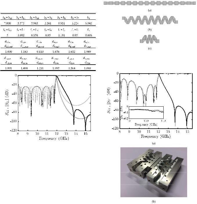
Fig. 9. (a) Structure formed by two consecutive −90° EMBs, responsible for the introduction of a transmission zero. Frequency response of the structure for the three examples with dimensions detailed in Table I: Tx zero 13 GHz (black line), Tx zero 14 GHz (thick gray line), and Tx zero 15 GHz (thin gray line). (b) Magnitude and (c) phase.
adjustment of all their parameters, see Fig. 9. To demonstrate the control that can be exerted over the position of the transmission zero, the two consecutive −90° EMBs structure of Fig. 9(a) has been designed for three examples, to provide the same frequency response (magnitude and phase) for a passband up to 11 GHz approximately, while introducing a

This article has been accepted for inclusion in a future issue of this journal. Content is final as presented, with the exception of pagination.
6 IEEE TRANSACTIONS ON MICROWAVE THEORY AND TECHNIQUES
|
|
TABLE I |
|
|
|
|
|
|
|
|
|
TABLE II |
||||||||||||||
DIMENSIONS FOR THE THREE EXAMPLES OF TWO CONSECUTIVE |
|
i AND DIMENSIONS (mm) OF THE Q-BAND MEANDERED BPFs |
||||||||||||||||||||||||
|
|
−90° EMBs STRUCTURES WITH DIFFERENT |
|
|
|
|
|
|
|
|
|
|
|
|
|
|
|
|
|
|
|
|
|
|
|
|
|
|
TRANSMISSION ZEROS (mm) |
|
|
|
|
|
|
|
|
|
|
|
|
|
|
|
|
|
|
|
|
|
|
|
|
|
|
|
|
|
|
|
|
|
|
|
|
|
|
|
|
|
|
|
|
|
|
|
|
|
|
|
|
|
|
|
|
|
|
|
|
|
|
|
|
|
|
|
|
|
|
|
|
|
|
|
|
|
|
|
|
|
|
|
|
|
|
|
|
|
|
|
|
|
|
|
|
|
|
|
|
|
|
|
|
|
|
|
|
|
|
|
|
|
|
|
|
|
|
|
|
|
|
|
|
|
|
|
|
|
|
|
|
|
|
|
|
|
|
|
|
|
|
|
|
|
|
|
|
|
|
|
|
|
|
|
|
|
|
|
|
|
|
|
|
|
|
|
|
|
|
|
|
|
|
|
|
|
|
|
|
|
|
|
|
|
|
transmission zero at 13, 14, and 15 GHz, respectively. The physical parameters of the three examples are given in Table I and the frequency responses obtained are shown in Fig. 9. As it can be seen, the transmission zero can be shifted toward lower and higher frequencies around 2 GHz (for these examples), while keeping the frequency response unaltered for the lower frequencies of the passband. Unfortunately, these transmission zeros cannot be achieved in the meandered BPFs, since the distance between the input and the output ports of the two consecutive −90° EMBs structure of Fig. 9 is around li ≈ λg, fπ /2 for the BPFs, and cannot be reduced as in the novel meandered LPFs case.
Finally, it is important to note that the aim of the proposed meandered filters is to operate with the fundamental TE10 mode in the required passband and stopband. If the suppression of higher order modes is also desired in the stopband, a waveguide width modification (in the x -axis) following [34] could be also included.
The design methods presented in this paper are based on a simple modular procedure which can be easily introduced in a software tool. In fact, the ±90° EMBs which compose the different structures are very simple, and the dimensions of each ±90° EMB are obtained in a negligible computing time. At this point, it is important to note that the same kind of optimizations are necessary in the classical design process of in-line corrugated waveguide LPFs due to the effect of higher-order mode excitation at the discontinuities between the adjacent waveguides of different heights [30]. Moreover, the routing of the structure can be easily achieved with the proposed meandered filters, avoiding the use of subsequent bends, reducing the insertion loss, mass, and PIM. In addition, the proposed techniques open the door to more complex routing structures with different angles.
III. DESIGN EXAMPLES
Two different filter specifications have been defined to demonstrate the performance of the proposed design techniques for the novel rectangular waveguide meandered filters: a Q-band BPF and a Ku-band LPF.
A. Q-Band Meandered BPF
The novel meandered topology for rectangular waveguide BPFs has been proven by targeting the same state-of-the-art frequency specifications as in [35]. The meandered filter will have a passband between 37.5 and 42.5 GHz, with in-band return loss better than 20 dB. The minimum attenuation required for the upper stopband (47–50 GHz) will be 65 dB. In addition, a rejection level of 65 dB will also be required for the lower stopband (34–35 GHz).
In order to fulfill the previous frequency specifications, a meandered BPF will be designed using the novel technique explained in Section II-A. After including the usual design margin, a 13th-order Chebyshev function is chosen, with a return loss level of 25 dB on the passband defined between f1 = 37 GHz and f2 = 43 GHz. The width of the rectangular waveguide is fixed to a = 4.65 mm. The input port height has been set to b0 = 1.4 mm, to avoid the coupling to the resonant TE011 mode inside the structure up to fmax = 50 GHz. Finally, the free parameters that adjust the shape of the bends di,in and di,out (see Fig. 1) have been fixed to 0.5 mm for all the ±90° EMBs, since they have no influence to obtain transmission zeros which are not possible in the BPF case.
Thus, using (5), the electrical length results in θc = 0.6938 rad for our design, and applying the unit element extraction procedure the characteristic impedance list is obtained: Z0 = Z14 = 1, Z1 = Z13 = 0.67, Z2 = Z12 = 1.84,
Z3 = Z11 = 0.41, Z4 = Z10 = 2.35, Z5 = Z9 =
0.37, Z6 = Z8 = 2.46, and Z7 = 0.36. Next, using (2), the target reflection coefficients i are calculated, and then the physical dimensions of each ±90° EMB (bi , li,in, and li,out) are computed to satisfy (7), (9), and (10). FEST3D is employed for the electromagnetic simulation and adjustment of each
±90° EMB. The final dimensions of the ±90° EMBs are given in Table II [after applying (11)]. To demonstrate the equivalence between the designed ±90° EMBs and their corresponding sections of the stepped-impedance prototype (see Fig. 5), their frequency responses are compared in Fig. 10 for the first (initial) and the seventh (central) ±90° EMBs. A remarkable wideband agreement is achieved between the frequency responses and the theoretical required values: | 1| = 0.201,
| 7| = 0.743, see Table II, and φ1,S11 ( fπ ) = φ7,S11 ( fπ ) = 0 and φ1,S21 ( fπ ) = φ7,S21 ( fπ ) = −π , see (10) and (4).
If the ±90° EMBs are cascaded following a compact arrangement (− + + − − + + · · · − −+) in accordance with Fig. 7(b), the frequency response of the resulting meandered BPF (with no final optimization) is shown in Fig. 11.

This article has been accepted for inclusion in a future issue of this journal. Content is final as presented, with the exception of pagination.
TEBERIO et al.: RECTANGULAR WAVEGUIDE FILTERS WITH MEANDERED TOPOLOGY |
7 |
|||||
|
|
|
|
|
|
|
|
|
|
|
|
|
|
|
|
|
|
|
|
|
|
|
|
|
|
|
|
|
|
|
|
|
|
|
Fig. 11. (a) CST MWS simulated (gray thick line) and measured (black line) frequency response of the novel meandered BPF designed with the technique in Section II-A, and simulated frequency response of the in-line BPF (gray thin line). |S11| in dotted line and |S21| in solid line. Inset: side view of the simulated meandered BPF. (b) Photograph of the unassembled prototype.
Fig. 10. (a) Magnitude and (b) phase of the frequency response of the first and seventh EMBs designed for the Q-band meandered BPF (black thick line) versus the frequency response of their corresponding sections of the steppedimpedance prototype (gray thin line).
Its equivalent in-line BPF has been also designed following [35]. As it can be seen in Fig. 7, the total length of the structure has been significantly reduced. The length of the novel meandered BPF is only 37.6 versus 81 mm for the in-line BPF (more than 50%-length reduction). Finally, as it can be seen in Fig. 11, the simulated frequency response of both filters is in very good agreement. The novel meandered BPF has been fabricated in clam-shell configuration, in bare aluminum, by standard milling with a radius of the drill equal to 200 μm. A photograph of the prototype is shown in Fig. 11. In order to reach the standard WR22 ports for the measurements, two-impedance transformers have been added to the input and output ports of the structure. The measurement results are also given in Fig. 11. A very good agreement between the simulation and the measured results is obtained.
One of the most remarkable features of the novel design method proposed in this paper is that, since it is a modular design procedure, once all the ±90° EMBs are calculated, they can be connected as the designer desires. In order to demonstrate the high versatility and great flexibility of the meandered structures proposed, different topologies have been simulated, fabricated, and measured. Using the ±90° EMBs
Fig. 12. Simulated frequency response of a different topology of meandered BPF designed with the technique in Section II-A. FEST3D simulation in gray line and CST MWS in black line. |S11| in dotted line and |S21| in solid line. Inset: side-view of the simulated BPF.
designed for the example in Fig. 11 without any final optimization in their physical parameters (the physical dimensions employed are exactly those given in Table II), different ad hoc layouts are proposed in Figs. 12 and 13. As it is shown in Figs. 12 and 13, the frequency response of both structures fulfills the specifications. In addition, the meandered BPF of Fig. 13 has been fabricated and measured employing the same procedures detailed above. The measurement results are also given in Fig. 13. A good agreement between the simulations and the measurements is achieved, proving that filters with

This article has been accepted for inclusion in a future issue of this journal. Content is final as presented, with the exception of pagination.
8 |
IEEE TRANSACTIONS ON MICROWAVE THEORY AND TECHNIQUES |
TABLE III
DIMENSIONS OF THE Ku-BAND MEANDERED LPF (mm)
Fig. 13. (a) CST MWS simulated (gray thick line) and measured (black line) frequency response of the novel meandered BPF designed with the technique in Section II-A. |S11| in dotted line and |S21| in solid line. Inset: side-view of the simulated meandered BPF. (b) Photograph of the unassembled prototype.
flexible routing capabilities can be obtained using the novel design technique and structures proposed in this paper.
B. Ku-Band Meandered LPF
In order to demonstrate the novel meandered topology for rectangular waveguide LPFs proposed in Section II-B, a compact LPF for Ku-band will be designed. The frequency specifications will be the same as in [33]: passband defined between 10.7 and 11.7 GHz, with in-band return loss better than 20 dB, and stopband defined between 13.75 and 14.5 GHz, with attenuation level higher than 60 dB.
To fulfill the previous frequency specifications, a 11th-order Chebyshev function will be employed. The maximum frequency of the passband, fc , and the frequency of maximum rejection, f0, are set equal to fc = 11.85 GHz and f0 = 17 GHz. The in-band return loss will be 25 dB. The slope between the passband and the stopband will be reinforced by the introduction of three transmission zeros close to the passband. The width of the filter is fixed to a = 19.05 mm, and the input port height is b0 = 7 mm. Now, using (12), the electrical length results in θc = 0.9236 rad for our design. Next, applying the unit element extraction procedure, the list of the characteristic impedances for the stepped-impedance prototype is obtained: Z0 = Z12 = 1, Z1 = Z11 = 0.75, Z2 = Z10 = 1.32, Z3 = Z9 = 0.60, Z4 = Z8 = 1.62, Z5 = Z7 = 0.53, and Z6 = 1.69. Then, the required local reflection coefficients i are calculated using (2). Now, as explained
Fig. 14. FEST3D simulated frequency response comparison between the novel LPF designed with the technique in Section II-B (gray line) and after the final adjustment of the filter parameters (black line). |S11| in dotted line and |S21| in solid line.
in Section II-B, each ±90° EMB is sequentially computed. For the i th ±90° EMB, di,in, di,out, and bi are computed to satisfy (13) (taking into account that bi−1 is fixed in the previous ±90° EMB), while li,in and li,out are computed to satisfy (14) and (15). In addition, as explained in Section II-B, each two consecutive −90° EMBs (or +90° EMBs) can produce a transmission zero, and it will be possible to generate three transmission zeros close to the passband in our design. FEST3D is used as electromagnetic simulator for the previous calculations and parameter adjustments. The dimensions obtained are listed in Table III [after applying (16)]. The frequency response of the filter designed is shown in Fig. 14. Although a clear passband is achieved, its matching must be improved (obtained return loss better than 15 dB) and a frequency shift appears. To solve those problems, a fine adjustment over the di ’s and li ’s is run. The final dimensions of the filter are detailed in Table IV. The frequency response of the filter obtained after the adjustment fully satisfies the prescribed specifications and is also shown in Fig. 14. Unlike in the previous meandered BPFs, a final quick optimization over the di ’s and li ’s has been required. This is due to the interaction of the transmission zeros with the implemented Chebyshev frequency response. That interaction cannot be neglected in our case of transmission zeros close to the passband, but it
This article has been accepted for inclusion in a future issue of this journal. Content is final as presented, with the exception of pagination.
TEBERIO et al.: RECTANGULAR WAVEGUIDE FILTERS WITH MEANDERED TOPOLOGY |
9 |
TABLE IV
DIMENSIONS OF THE Ku-BAND MEANDERED LPF AFTER THE
ADJUSTMENT OVER THE di ’s AND li ’s (mm)
Fig. 15. FEST3D simulated frequency response comparison between the classical straight LPF designed following [32] (gray thin line), the LPF with meandered topology in [33] (gray thick line), and the LPF with transmission zeros designed in this paper (black line), all fulfilling the same frequency specifications. |S11| in dotted line and |S21| in solid line.
is easily compensated with the final quick optimization over the di ’s and li ’s explained. The novel filter designed in our example has three transmission zeros in the required stopband. The first zero is located at 13.75 GHz (produced by the sixth–seventh consecutive −90° EMBs), and a double zero is located at 15 GHz (produced by the fourth–fifth consecutive +90° EMBs, and their symmetrical eighth–ninth consecutive +90° EMBs). In addition, two transmission zeros (a double zero) located at higher frequencies (not used in our design) are produced by the second–third consecutive −90° EMBs, and their symmetrical 10th–11th consecutive −90° EMBs.
As a general rule, a filter of order N (odd for simplicity) will feature N + 1 ±90° EMBs. Each two consecutive −90° EMBs (or +90° EMBs) can produce a transmission zero. Assuming that the topology selected is the most compact like in our example (i.e., + − − + + − − + + · · · − −+), there will be (N − 1)/2 two consecutive −90° EMBs (or +90° EMBs) which can produce a transmission zero. Finally, assuming symmetry in the stepped-impedance prototype (as it happens for Butterworth or Chebyshev functions) the transmission zeros will be grouped in pairs except for a possible single transmission zero.
Fig. 16. Side view (same scale) of (a) classical straight LPF designed following [32] (b) filter with meandered topology in [33], and (c) filter with transmission zeros designed in this paper, all fulfilling the same frequency specifications.
Fig. 17. (a) Comparison between the CST MWS simulated frequency response (gray line) of the meandered LPF with transmission zeros and measurements of the fabricated prototype (black line). |S11| in dotted line and |S11| in solid thick line. (b) Photograph of the unassembled fabricated prototype. Inset: detail of the insertion loss.
It is worth noting that the minimum mechanical gap of the final structure obtained in our design example is larger than 3.5 mm, which will provide high-power handling capability as customarily needed. The high-power behavior of the novel filter has been estimated by means of SPARK3D, using the EM fields previously calculated with CST MWS. The highpower simulation has been performed at 11.7 GHz (upper passband edge, where the EM fields are maximum and the
This article has been accepted for inclusion in a future issue of this journal. Content is final as presented, with the exception of pagination.
10
input power threshold will be minimum), using the SEY of silver (ECSS, [36]). The input power theshold level of the proposed LPF is higher than 20 kW, which is a very high value comparable with those that can be found in [23] and [37].
The novel meandered LPF with transmission zeros designed has been compared with the classical inline LPF designed following [32], and the meandered LPF structure proposed in [33]. Their simulated frequency responses are compared in Fig. 15, and a side view of the filters is shown in Fig. 16. As it can be seen, all the filters fulfill the frequency specifications, but the novel filter proposed in this paper is more compact than its counterparts. Actually, the novel filter is only 29.3-mm long, while the filter in [33] is 104.5-mm long and the inline filter is 180.1-mm long (more than 70% and 83% of length reduction, respectively).
The novel meandered LPF with transmission zeros has been fabricated in clam-shell configuration, in bare aluminum, by standard milling with a radius of the drill equal to 1 mm. A photograph of the prototype is shown in Fig. 17. In order to reach the standard WR75 ports for the measurements, two impedance transformers of 1 step have been added to the input and output ports of the structure. The measurement results are also given in Fig. 17. A remarkable agreement between the simulated (including the impedance transformers) and the measured results is obtained. A detail with the insertion loss of the filter at the passband is shown in Fig. 17 inset. As it can be seen, the measured insertion loss for the LPF is below 0.1 dB.
IV. CONCLUSION
In this paper, a new meandered topology for rectangular waveguide LPFs and BPFs is proposed. The novel filters cascade ±90° EMBs whose physical dimensions are calculated in a simple modular manner that can be easily integrated in an electromagnetic software tool. Furthermore, due to its modular nature, different lay-out configurations can be achieved without further optimizations, allowing us to obtain ad hoc designs with routing capabilities to adapt to specific circuit footprints. In addition, in the case of the novel meandered LPFs, transmission zeros can be introduced, producing very steep slopes between the passband and the stopband. Moreover, the novel meandered topology allows for more compact structures in comparison with the state-of-the-art filters. Several examples, three BPFs and one LPF, have been designed and simulated to demonstrate the aforementioned characteristics. Two BPFs and one LPF have been also fabricated by milling, and the measurements of the prototypes show an excellent agreement with the simulation results, confirming the robustness of the novel filter topology and its design method.
ACKNOWLEDGMENT
The authors would like to thank the help of Microlan S. L., Huarte, Spain, with the fabrication of the Q-band prototypes.
REFERENCES
[1]J. Uher, J. Bornemann, and U. Rosenberg, Waveguide Components for Antenna Feed Systems: Theory and CAD. Norwood, MA, USA: Artech House, 1993.
IEEE TRANSACTIONS ON MICROWAVE THEORY AND TECHNIQUES
[2]V. E. Boria and B. Gimeno, “Waveguide filters for satellites,” IEEE Microw. Mag., vol. 8, no. 5, pp. 60–70, Oct. 2007.
[3]R. J. Cameron, C. M. Kudsia, and R. R. Mansour, Microwave Filters for Communication Systems: Fundamentals, Design and Applications. Hoboken, NJ, USA: Wiley, 2007.
[4]M. Skolnik et al. Radar handbook, Electronics Electrical Engineering, 3rd ed. New York, NY, USA: McGraw-Hill, 2008.
[5]S. Ceccuzzi, C. Ponti, G. L. Ravera, and G. Schettini, “Physical mechanisms and design principles in mode filters for oversized rectangular waveguides,” IEEE Trans. Microw. Theory Techn., vol. 65, no. 8, pp. 2726–2733, Aug. 2017.
[6]H. Wolf, M. Schneider, S. Stirland, and D. Scouarnec, “Satellite multibeam antennas at airbus defence and space: State of the art and trends,” in Proc. 8th Eur. Conf. Antennas Propag. (EuCAP), The Hague, The Netherlands, Apr. 2014, pp. 182–185.
[7]H. Moheb, C. Robinson, and J. Kijesky, “Design & development of co-polarized Ku-band ground terminal system for very small aperture terminal (VSAT) application,” in IEEE Antennas Propag. Soc. Int. Symp. Dig./USNC/URSI Nat. Radio Sci. Meeting, Orlando, FL, USA, vol. 3, Jul. 1999, pp. 2158–2161.
[8]X. Zhao et al., “Analytic passive intermodulation model for flange connection based on metallic contact nonlinearity approximation,” IEEE Trans. Microw. Theory Techn., vol. 65, no. 7, pp. 2279–2287, Jul. 2017.
[9]C. Vicente, D. Wolk, H. L. Hartnagel, and D. Raboso, “An experimental investigation on passive intermodulation at rectangular waveguide interfaces,” in IEEE MTT-S Int. Microw. Symp. Dig., San Francisco, CA, USA, Jun. 2006, pp. 242–245.
[10]A. Morini, T. Rozzi, and M. Mongiardo, “Curved filters in rectangular waveguide,” in Proc. 26th Eur. Microw. Conf., Prague, Czech Republic, Sep. 1996, pp. 153–154.
[11]C. Wang, K. A. Zaki, A. E. Atia, and T. G. Dolan, “Dielectric combline resonators and filters,” IEEE Trans. Microw. Theory Techn., vol. 46, no. 12, pp. 2501–2506, Dec. 1998.
[12]M. Yu, W.-C. Tang, A. Malarky, V. Dokas, R. Cameron, and Y. Wang, “Predistortion technique for cross-coupled filters and its application to satellite communication systems,” IEEE Trans. Microw. Theory Techn., vol. 51, no. 12, pp. 2505–2515, Dec. 2003.
[13]T. Shen and K. A. Zaki, “Folded evanescent-mode ridge waveguide bandpass filters,” in Proc. 31st Eur. Microw. Conf., London, U.K., Sep. 2001, pp. 1–4.
[14]E. Ofli and R. Vahldieck, “A novel compact millimeter wave diplexer,” in IEEE MTT-S Int. Microw. Symp. Dig., Seattle, WA, USA, vol. 1, Jun. 2002, pp. 377–380.
[15]M. Guglielmi, F. Montauti, L. Pellegrini, and P. Arcioni, “Implementing transmission zeros in inductive-window bandpass filters,” IEEE Trans. Microw. Theory Techn., vol. 43, no. 8, pp. 1911–1915, Aug. 1995.
[16]C. Tomassoni, L. Marcaccioli, M. Dionigi, M. Mongiardo, R. V. Gatti, and R. Sorrentino, “CAD of folded filters and diplexers by the generalized scattering matrix of the single step discontinuity,” in IEEE MTT-S Int. Microw. Symp. Dig., vol. 3, Jun. 2004, pp. 1843–1846.
[17]J. Bornemann, S. Amari, and R. Vahldieck, “A flexible S-matrix algorithm for the design of folded waveguide filters,” in Proc. Eur. Microw. Conf., Oct. 2005, p. 4.
[18]C. Carceller, P. Soto, V. Boria, M. Guglielmi, and D. Raboso, “New folded configuration of rectangular waveguide filters with asymmetrical transmission zeros,” in Proc. 44th Eur. Microw. Conf., Rome, Italy, Oct. 2014, pp. 183–186.
[19]U. Rosenberg, M. Knipp, and S. Amari, “Compact diplexer design using different E-plane triplets to serve contiguous passbands with high interband selectivity,” in Proc. Eur. Microw. Conf., Manchester, U.K., Sep. 2006, pp. 133–136.
[20]C. Carceller, P. Soto, V. E. Boria, and M. Guglielmi, “Design of hybrid
folded rectangular waveguide filters |
with transmission zeros |
below |
the passband,” IEEE Trans. Microw. |
Theory Techn., vol. 64, |
no. 2, |
pp. 475–485, Feb. 2016.
[21]F. Teberio et al., “Chirping techniques to maximize the power-handling capability of harmonic waveguide low-pass filters,” IEEE Trans. Microw. Theory Techn., vol. 64, no. 9, pp. 2814–2823, Sep. 2016.
[22]I. Arregui et al., “High-power low-pass harmonic filters with higherorder TEn0 and non-TEn0 mode suppression: Design method and multipactor characterization,” IEEE Trans. Microw. Theory Techn., vol. 61, no. 12, pp. 4376–4386, Dec. 2013.
[23]O. A. Peverini et al., “Enhanced topology of E -plane resonators for high-power satellite applications,” IEEE Trans. Microw. Theory Techn., vol. 63, no. 10, pp. 3361–3373, Oct. 2015.