

диафрагмированные волноводные фильтры / b6559dde-c6f4-46a2-81d3-1e6ab0ecf96a
.pdf4376 |
IEEE TRANSACTIONS ON MICROWAVE THEORY AND TECHNIQUES, VOL. 61, NO. 12, DECEMBER 2013 |
High-Power Low-Pass Harmonic Filters With Higher-Order 

 and Non-

 Mode Suppression: Design Method and Multipactor Characterization
Ivan Arregui, Fernando Teberio, Israel Arnedo, Aintzane Lujambio, Magdalena Chudzik, David Benito, Txema Lopetegi, Rolf Jost, Franz-Josef Görtz, Jordi Gil, Carlos Vicente, Benito Gimeno, Vicente E. Boria, David Raboso, and Miguel A. G. Laso
Abstract—In this paper, a method to design high-power low-pass harmonic filters in rectangular waveguide technology is proposed. The new filters consist of a collection of smooth E-plane bandstop elements along the propagation direction and a smooth variation of the filter width. This yields to a broad rejected band for the fundamental 


 mode, together with higher-order (


 and non-

 ) mode suppression. Two different examples with stringent requirements of the space industry are provided to demonstrate the capabilities of the new methodology. By means of high-power simulations and an extensive measurement campaign, it will be shown that the smoothness of the filter profile guarantees high-power operation even with small minimum mechanical gaps. Moreover, unlike classical techniques, our method is not restricted to filters with small gaps. Hence, filters with larger gaps (always fulfilling the demanding frequency specifications) are fabricated for even higher power-handling performance.
Index Terms—High-power, low-pass harmonic filter, multipactor, radio-frequency (RF) breakdown threshold, rectangular waveguide.
I. INTRODUCTION
M ICROWAVE filters are essential devices employed in many fields, such as the communications satellite industry. When low insertion loss and high power-handling
Manuscript received July 05, 2013; revised October 10, 2013; accepted October 16, 2013. Date of publication November 06, 2013; date of current version December 02, 2013. This work was supported in part by the Spanish CICYT under the project TEC2011-28664-C02-01. This paper is an expanded paper from the IEEE MTT-S International Microwave Symposium, Seattle, WA, USA, June 2013.
I.Arregui, F. Teberio, I. Arnedo, A. Lujambio, M. Chudzik, D. Benito, T. Lopetegi, and M. A. G. Laso are with the Electrical and Electronic Engineering Department, Public University of Navarre, Pamplona 31008, Spain (e-mail: ivan.arregui@unavarra.es).
R.Jost and F.-J. Görtz are with Tesat-Spacecom GmbH & Co. KG, 71522 Backnang, Germany.
J.Gil and C. Vicente are with Aurora Software and Testing, S. L., 46022 Valencia, Spain.
B.Gimeno is with the Departamento de Física Aplicada y Electromagnetismo, Instituto de Ciencia de Materiales (ICMUV), Universitat de València, Valencia 46022, Spain.
V.E. Boria is with the Departamento de Comunicaciones, Instituto de Telecomunicaciones y Aplicaciones Multimedia (iTEAM), Universidad Politécnica de Valencia, Valencia 46022, Spain.
D.Raboso is with the Payloads System Division, European Space Agency (ESA), 2200 AG Noordwijk, The Netherlands.
Color versions of one or more of the figures in this paper are available online at http://ieeexplore.ieee.org.
Digital Object Identifier 10.1109/TMTT.2013.2288208
capability are required, waveguide technology is used. The design of low-pass filters in rectangular waveguide to handle high-power, featuring a wide rejected band simultaneously, is of great interest for some applications, such as the output section of a satellite payload. The classical solutions for implementing low-pass filters in rectangular waveguide technology, such as the E-plane corrugated filters [1], [2], present a trade-off between the minimum mechanical gap and the highest rejected frequency. This limitation is overcome in [3]–[5], where high-power filters with wide rejected band for the fundamental 


 mode have been proposed. In [3], [4], a high-power non-wide rejection band E-plane corrugated filter is cascaded with several quasi-periodic E-plane sinusoidally-shaped waveguide sections, the former being responsible for the large minimum mechanical gap in the whole structure (which determines the maximum power handled by the total device) and the latter achieving the spurious rejection through an appropriate tuning of the sinusoidal perturbation periods (Bragg reflection). In [5], an integrated design methodology of compact high-power low-pass filters is proposed, where the filters consist of multiple E-plane bandstop elements of sinusoidal profile (although other profiles are also possible [6]) and the tuning of the rejected frequencies is achieved through the height of the bandstop elements and not through the period of the structure. Unlike [3], [4], the proposal in [5] is not based on the Bragg phenomenon and no corrugated filter is required with this methodology. A windowing of the quasi-periodic structure height allows the implementation of low-pass filters with deep levels of out-of-band rejection in a broad band and with good in-band return loss.
When the rejection of higher-order 


 modes is also required, devices based on evanescent-mode propagation [7]–[11] or the waffle-iron filters [12]–[14] have been proposed in the literature. For high-power operation, a design method has been developed in [15]. This technique is based on the method presented in [5] and the suppression of the higher-order


 modes is achieved by means of a quasi-periodic two-dimen- sional arrangement of E—plane bandstop elements. Another proposal has been presented in [16] to achieve the suppression of these higher-order modes through composite filters also designed using [5]. In [16], classical rectangular

 stubs as it is suggested in [6] are employed.
0018-9480 © 2013 IEEE

ARREGUI et al.: HIGH-POWER LOW-PASS HARMONIC FILTERS |
4377 |
In this paper, the design technique of [5] is also employed, but the suppression of the higher-order 


 modes is accomplished following the idea previously proposed in [17] to improve the frequency behavior of the classical corrugated filters. Following [17], an ad-hoc variation in the width of the filter of [5] is done, which leads to a simpler structure than the one presented in [15], showing even better insertion loss, and achieving much larger attenuation for the


 modes than the one obtained in [17]. The variation in the width is performed along one filter, avoiding the use of two filters with different width as it is proposed in [16]. Moreover, the non-


 modes can be rejected too since the minimum gap is an independent parameter in our design method. Even in this case, the minimum gap is still much larger than the one needed in the classical filters.
An important issue to be considered during the design of highpower microwave filters for communications satellites is the multipactor phenomenon [18]. Multipactor is a breakdown discharge occurring in microwave devices operating at high-power levels and in vacuum conditions, which is caused by the formation of an electron avalanche [19]. In order to estimate the maximum RF input power that a device is able to handle before multipactor occurs, several theoretical approaches are usually used [18], which can be summarized basically in two: the parallel-plate waveguide model and the particle-in-cell (PIC) algorithm. Although the par- allel-plate model provides an estimation of the RF input power threshold, in many occasions it is too restrictive and conservative. In order to make an accurate multipactor analysis, itis crucial to know the real electromagnetic field distribution inside the microwave device as well as the electron dynamics evolution, as the numerical PIC codes do. These methods can be used to estimate the threshold power of the multipactor from some input parameters, such as the operation frequency, the device geometry, and the material secondary emission yield (SEY) properties. Both the parallel-plate model and the PIC algorithm will be compared for our filters showing that the parallel-plate model yields very poor estimations due to the smoothness of the filter profiles (far from the parallel-plate assumption).
In [20], the possibility of using small minimum mechanical gaps but smooth profiles to get high multipactor threshold levels was validated, showing the interest of our structures with smooth profile for high-power applications. Since the method explained in this paper is not limited to small minimum mechanical gaps, devices with larger gaps have been now also characterized to fully demonstrate the potential of these devices in very high-power applications.
This paper is organized as follows. Section II details the proposed technique for the design of high-power low-pass harmonic filters with wide-band rejection of the 


 mode and higher-order (

 and non-

 ) mode suppression. In Section III, two examples are provided to validate the different possibilities of the design method. Moreover, the high power-handling capability of the new devices is proven by means of high-power simulations and an extensive measurement campaign in Section IV. Finally, the conclusions of this work are presented in Section V.
II. DESIGN METHOD
In the high-power low-pass filters proposed in [5], the 


and the higher-order 

 modes are only rejected in some fre-
Fig. 1. Frequency response of the fundamental 


 mode (solid line) and higher-order


 -mode behavior (dashed line) of the high-power filters presented in [5]: a) filter width equal to
 (waveguide-port width), b) filter width equal to

 , lower than
 , and c) two filters with different width (
 and
and 

 , respectively) cascaded.
quency ranges, as it happens with the classical E-plane corrugated filters [15]. Actually, the high-power filters in [5] and the classical corrugated filters have the same 


 -mode behavior. In [17], the following expression is used to predict the spurious responses:
|
|
|
|
|
|
|
|
|
|
|
|
|
|
|
|
|
|
|
|
|
|
|
|
|
|
|
|
|
|
|
|
|
|
|
|
|
|
|
|
|
|
|
|
|
|
|
|
|
(1) |
|||||||
where |
|
|
|
is the maximum frequency of the pass band of each |
||||||||||||||||||||||||||||||||||||||||||||||||||||
|
|
|||||||||||||||||||||||||||||||||||||||||||||||||||||||
|
|
|
|
|
mode and |
|
|
|
|
|
|
|
|
|
|
is the cutoff frequency of the |
|
|
|
|
|
|
|
mode. |
||||||||||||||||||||||||||||||||
Considering an example of a filter like in [5] with a constant width equal to the rectangular waveguide port, 
 , its frequency behavior is depicted in Fig. 1(a). Pass bands are observed, for each

 mode, between its cutoff frequency,
 , and the
maximum frequency of the pass band,  . A filter with the same
frequency response for the fundamental |
|
|
|
|
mode but a con- |
|||||||||
|
||||||||||||||
|
|
|
||||||||||||
stant width |
|
|
|
|
, lower than |
|
|
|
, can be also designed. In this |
|||||
|
|
|||||||||||||
|
|
|
|
|
|
|||||||||
|
|
|
|
|
|
|
|
|
|
|
|
|
|
|
case, shown in Fig. 1(b), the pass bands of the higher order 

 modes will be located at higher frequencies since the cor-
responding cutoff frequencies, |
|
|
|
|
|
|
, and |
|
|
|
|
|
are higher. |
|
||||
|
|
|
||||||||||||||||
Therefore, a filter to reject all |
|
the |
higher-order |
|
|
|
|
modes |
||||||||||
|
|
|
|
|
||||||||||||||
can be achieved if two filters with different width, like the ones with the frequency responses shown in Fig. 1(a) and Fig. 1(b), are cascaded. The use of at least two filters with a different width guarantees that the pass bands of the higher-order 

 modes
modes
of one filter are forced to coincide with the frequencies where these modes are rejected in the other filter. This is achieved if 


 (Fig. 1(c)). This condition is enough when the
filters present side-by-side symmetry, such as the filters proposed in this paper. However, in order to prevent the degradation of the higher-order 

 -mode suppression due to, for in-
stance, asymmetries created during the manufacturing process that produce mutual coupling between the higher-order 


4378 |
IEEE TRANSACTIONS ON MICROWAVE THEORY AND TECHNIQUES, VOL. 61, NO. 12, DECEMBER 2013 |
Fig. 2. Schematics showing a high-power low-pass filter with width reduction and suppression of the high-order modes: a) 3D view, b) side view, and c) top view.
modes, 


 should be also fulfilled (Fig. 1(c)). Actually, the same idea can be implemented using only one filter if different widths (in a stepwise or continuous way) are used along the device. Now, the pass bands of the higher-order

 modes are forced to coincide with the frequencies where these modes are rejected by other sections with a different width of the same filter. This concept was already used in [17] to design inhomogeneous stepped-impedance corrugated low-pass filters, not intended for high-power. Reference [17] extends the design of classical E-plane corrugated filters to reject higher-order modes and, although an improvement in the rejection of the higher-order

 modes is achieved, the attenuation obtained
for these modes is actually not very high. In this paper, much higher rejection levels will be obtained when the variation in the width is applied (in a continuous way) to the high-power filters explained in [5].
In order to implement this concept of a varying filter width to the high-power filters of [5], the next steps must be followed. First of all, a filter has to be designed with the aid of the method proposed in [5], taking into account the frequency specifications for the fundamental 


 mode only. Sinusoidal band-
stop elements are first disposed along the z axis, giving rise to
three different filter sections: |
|
|
|
, which mainly determines the |
|||||||||||||||||||||||||||||||||
|
|
||||||||||||||||||||||||||||||||||||
|
|
|
|||||||||||||||||||||||||||||||||||
filter rejected band, and |
|
|
and |
|
|
|
|
, which mainly determine the |
|||||||||||||||||||||||||||||
|
|
|
|||||||||||||||||||||||||||||||||||
|
|
|
|
||||||||||||||||||||||||||||||||||
in-band return loss (Fig. 2). Specifically, in |
|
|
we set the heights |
||||||||||||||||||||||||||||||||||
|
|||||||||||||||||||||||||||||||||||||
|
|
||||||||||||||||||||||||||||||||||||
of the highest |
|
|
|
|
|
|
|
|
|
|
and shortest |
|
|
|
|
|
|
|
|
|
|
E-plane bandstop el- |
|||||||||||||||
|
|
|
|
|
|
||||||||||||||||||||||||||||||||
|
|
|
|
|
|
|
|
|
|
|
|
|
|
|
|
|
|
|
|
||||||||||||||||||
ements, which |
are around |
|
|
|
|
|
-long at the rejected-band lowest |
||||||||||||||||||||||||||||||
|
|
|
|
|
|||||||||||||||||||||||||||||||||
|
|
|
|
|
|
|
|
|
|
|
|
|
|
|
|
|
|
|
|
|
|
|
|
|
|
|
|
|
|
|
|
|
|
|
|
|
|
|
|
|
|
|
|
|
|
|
|
|
|
|
|
|
and highest |
|
|
|
|
|
|
|
|
|
|
|
|
|
|
|
frequency, respectively. Be- |
||||||
|
|
|
|
|
|
|
|
|
|
|
|||||||||||||||||||||||||||
|
|
|
|
|
|
|
|
|
|
|
|
|
|
||||||||||||||||||||||||
|
tween |
|
|
|
|
|
|
|
|
|
|
and |
|
|
|
|
|
, |
|
several bandstop elements with inter- |
|||||||||||||||||
|
|
|
|
|
|
|
|
|
|
||||||||||||||||||||||||||||
|
|
|
|
|
|
|
|
|
|
|
|
|
|
|
|
|
|||||||||||||||||||||
mediate heights are used to reject the intermediate frequencies. As the number of bandstop elements between the highest and the shortest increases, the attenuation in the rejected band can be made higher. Moreover, if we include in section 
 several
additional bandstop elements with the largest height, the slope between the pass and the rejected bands can be made steeper, since these additional elements reinforce the suppression of the lowest frequencies in the rejected band. 
 and
and 
 consist of
several bandstop elements that are windowed to achieve the height, 
 , of the port standard being used. If we increase the
number of bandstop elements in section |
|
|
and |
|
|
|
, the filter |
|
|
||||||
|
|
|
|||||
|
|
is better matched (higher in-band return loss). As explained in [5], since the rejection is achieved through the bandstop element height,  , and not through its length,
  , and no distance between the bandstop elements is needed, very compact devices can be
designed. Afterwards, the minimum width of the filter, |
|
|
|
|
|
|
|
|
|
, |
||||||||||||||||||||||||||||||||||||||||||||||||||||||
must be fixed low enough to guarantee that |
|
|
|
|
|
|
|
|
|
|
|
|
|
|
|
|
|
|
and |
|||||||||||||||||||||||||||||||||||||||||||||
|
|
|
|
|
|
|
|
|
|
|
|
|
|
|
|
|
|
are satisfied (except, of course, |
|
|
|
for the funda- |
||||||||||||||||||||||||||||||||||||||||||
|
mental |
|
|
|
|
mode, |
|
|
|
|
|
). A trade-off exists for the minimum |
||||||||||||||||||||||||||||||||||||||||||||||||||||
value of |
|
|
|
|
, since the cutoff frequency of the fundamental |
|||||||||||||||||||||||||||||||||||||||||||||||||||||||||||
|
|
|
|
|
|
|
|
mode must be low enough to keep the intended |
|
|
|
|
|
|
|
|
|
|
pass |
|||||||||||||||||||||||||||||||||||||||||||||
|
|
|
|
|
|
|
|
|
|
|
|
|
|
|
||||||||||||||||||||||||||||||||||||||||||||||||||
band, i. e., |
|
|
|
|
|
|
|
|
must fulfill |
(2) |
||||||||||||||||||||||||||||||||||||||||||||||||||||||
|
|
|
|
|
|
|
|
|
|
|
|
|
|
|
|
|
|
|
|
|
|
|
|
|
|
|
|
|
|
|
|
|
|
|
|
|
|
|
|
|
|
|
|
|
|
|
|
|
|
|
|
|
|
|
||||||||||
|
|
|
|
|
|
|
|
|
|
|
|
|
|
|
|
|
|
|
|
|
|
|
|
|
|
|
|
|
|
|
|
|
|
|
|
|
|
|
|
|
|
|
|
|
|
|
|
|
|
|
|
|
|
|
||||||||||
|
|
|
|
|
|
|
|
|
|
|
|
|
|
|
|
|
|
|
|
|
|
|
|
|
|
|
|
|
|
|
|
|
|
|
|
|
|
|
|
|
|
|
|
|
|
|
|
|
|
|
|
|
|
|
||||||||||
where 


 is the lowest frequency of the pass band,
 is the permeability of vacuum, and
 is the permittivity of vacuum. The length of the section with the minimum width,
  , must be large enough to avoid that the evanescent mode propagation could be significant. Once the minimum width is fixed, the transition between the standard waveguide ports,
 , and the minimum width,


 , must be defined. In order to preserve the good return loss of the filter, a slow variation of the width must be performed, for instance, by means of a Hanning window with length
 . Hence, unlike in [17], the width variation is continuous and not stepwise. The longer the window used the lower influence it has on the return loss of the designed filter. Finally, the height of the bandstop elements whose width values have been noticeably reduced may need to be finely tuned to larger values to fulfill the required rejected band of the fundamental


 mode. However, this is a slight tuning process as the response of the bandstop element is mainly determined by its height and not by its width [5].
If the rejection of the other higher non-


 modes is also a requirement, we must ensure during the design process that the minimum gap of the filter,


 , is fixed to avoid the propagation of the first higher-order non-


 mode, i. e., the


 mode. In other words, the cutoff frequency of the


 mode must be larger than the highest frequency of the rejected band,


 . This happens when


 fulfills
(3)
This can be made possible since 


 is an independent parameter for the fundamental


 mode and the higher-order

 modes in the design technique in which this method is based [5].

ARREGUI et al.: HIGH-POWER LOW-PASS HARMONIC FILTERS
TABLE I
DIMENSIONS OF THE NOVEL HIGH-POWER LOW-PASS HARMONIC WAVEGUIDE
FILTER WITH WIDTH REDUCTION AND SUPPRESSION OF THE HIGHER-ORDER


 MODES (WR75 PORTS:


 ,
, 


 )
)
 : 3.825 mm and total filter length
  : 218 mm
Fig. 3. Simulated frequency response of the novel filter with minimum gap of 5 mm using CST Microwave Studio: fundamental 


 mode behavior and higher-order


 mode suppression. Cutoff frequencies of the higher-order modes at the WR75 waveguide ports are shown in dotted line.
III. DESIGN EXAMPLES
|
Following the |
aforementioned method, two WR75 de- |
|||||||||||||||||||||||||||||||||||||||||
vices have been |
designed fulfilling a pass band between |
||||||||||||||||||||||||||||||||||||||||||
|
|
|
|
|
|
|
|
|
|
|
|
|
|
|
|
|
|
and |
|
|
|
|
|
|
|
|
|
|
|
|
|
|
|
|
|
|
|
|
|
|
|
|
with |
a return loss better than 20 dB. Moreover, a rejected band
from |
|
|
|
|
|
|
|
|
|
|
|
|
|
|
|
|
|
|
|
|
|
|
|
|
|
|
|
|
|
|
up to the third harmonic |
|||||
|
|
|
|
|
|
|
|
|
|
|
|
|
|
|
|
|
|
|
|
|
|
|
|
|
|
|
|
|
|
|
with attenuation higher than 60 dB |
|||||
is imposed. Specifically, the first example will be designed
to achieve the suppression of the fundamental |
|
|
|
|
|
|
|
and the |
||||||||||||||||||
|
|
|
|
|||||||||||||||||||||||
|
|
|
|
|
|
|||||||||||||||||||||
|
|
|
||||||||||||||||||||||||
higher-order |
|
|
|
|
modes whereas the second one will reject |
|||||||||||||||||||||
|
||||||||||||||||||||||||||
|
|
|
|
|||||||||||||||||||||||
all the higher-order ( |
|
|
|
|
and non- |
|
|
|
|
|
|
|
) |
modes. These |
||||||||||||
|
|
|
||||||||||||||||||||||||
specifications have been also used in [5] and [15] to validate the design methods. Less stringent specifications (specifically, a poor transition between the pass and the rejected bands) are employed in [16].
A. Suppression of the Higher-Order 


 Modes
Modes
The dimensions of the filter designed for the suppression of the higher-order 

 modes with a minimum mechanical gap equal to 5 mm are shown in Table I. As it can be seen in its simulated frequency response, see Fig. 3, the specifications for the fundamental mode are fulfilled, while a large attenuation is also achieved for the higher-order

 modes. The filter has been fabricated by electroforming in copper (see Fig. 4—inset—). In Fig. 4, the measured


 -mode frequency response of the novel filter (black line) is shown, fulfilling the specifications with an in-band insertion loss better than 0.30 db, along with the measured frequency response of the filter proposed in [5]. More-
4379
Fig. 4. Measured frequency response of the 


 mode (obtained without 90
 H-plane bends in the measurement set-up) for the novel high-power filter with minimum gap of 5 mm (black line) and for the high-power filter in [5] (grey
line): |
|
|
|
|
|
|
|
|
|
is given in dashed line and |
|
|
|
|
|
|
|
|
|
in solid line. The frequency speci- |
||||||||||||||||
fication |
|
|
|
mask for |
|
|
|
|
|
|
|
and |
|
|
|
|
|
|
|
is also given in dotted line. Inset: photograph |
||||||||||||||||
of the fabricated |
prototype. |
|
|
|
|
|
|
|
|
|
|
|
|
|
|
|
|
|
|
|||||||||||||||||
Fig. 5. Measured |
|
|
|
|
|
|
|
|
|
frequency response of the |
|
|
|
|
|
|
|
mode (obtained with |
90 H-plane bends |
|
|
in the measurement set-up) for the novel high-power filter |
|||||||||||||||
with minimum gap of 5 mm (black line) and for the high-power filter in [5] (grey line).
over, following [21], 90 H-plane bends have been employed in our experimental set-up to validate with a single measurement the rejection of all the higher-order

 modes, as predicted in simulation in Fig. 3. If asymmetric discontinuities such as 90
 H-plane bends are connected at the filter input and output ports, then the


 -mode input power will be partially coupled to the higher-order

 modes. If these modes are not rejected by the filter, they will be coupled back to the


 mode at the output discontinuity, thus producing spurious pass-bands in the frequency response of the


 mode measured by a Vector Network Analyzer (VNA). Using this measurement set-up, the filter of [5] shows spurious bands that correspond with the regions where it is not able to suppress the higher-order

 modes, while now the novel filter features excellent higherorder

 -mode suppression, as expected (see Fig. 5). Even higher rejection levels could be obtained if the spuriously excited non-

 modes in the measurement set-up were also suppressed in the filter, as we do in our next example.
B. Suppression of All the Higher-Order Modes
As it has been explained in the previous Section, the minimum mechanical gap of the filter, 
 , must be fixed to en-

4380 |
IEEE TRANSACTIONS ON MICROWAVE THEORY AND TECHNIQUES, VOL. 61, NO. 12, DECEMBER 2013 |
Fig. 6. Simulated frequency response of the novel filter with minimum gap of 3 mm using CST Microwave Studio: (a) fundamental 


 mode behavior and higher-order


 mode suppression, and (b) suppression of the non-


 higher-order modes. Cutoff frequencies of the higher-order modes at the WR75 waveguide ports are shown in dotted line.
Fig. 7. Measured frequency response of the 


 mode (obtained without 90
 H-plane bends in the measurement set-up) for the novel high-power filter with minimum gap of 3 mm (black line) and the high-power filter in [5] (grey line):
|
|
|
|
|
|
|
|
|
is given in dashed line and |
|
|
|
|
|
|
|
|
|
in solid line. The frequency specification |
|||||||||||||||||||||||||
|
mask |
|
for |
|
|
|
|
|
|
|
|
|
and |
|
|
|
|
|
|
|
|
|
is also |
|
given in dotted line. Inset: photograph of the |
|||||||||||||||||||
fabricated |
|
|
prototype. |
|
|
|
|
|
|
|
|
|
|
|
|
|
|
|
|
|
|
|
|
|
|
|||||||||||||||||||
sure that the cutoff frequency of the |
|
|
|
|
mode is larger than |
|||||||||||||||||||||||||||||||||||||||
|
||||||||||||||||||||||||||||||||||||||||||||
|
|
|
||||||||||||||||||||||||||||||||||||||||||
|
|
|
|
|
|
|
|
|
|
|
|
|
|
|
|
|
|
|
|
|
|
|
|
|
|
|
|
|
|
|
|
|
|
|
|
|
|
|
|
|
|
|
|
|
the highest frequency of the rejected band. In this case, a value
of |
|
|
|
|
|
|
|
|
|
|
|
|
|
has been chosen since it leads to a cutoff |
||||||||||||
|
|
|
|
|
|
|
|
|
|
|||||||||||||||||
frequency of the |
|
|
|
|
|
|
|
mode equal to 49 GHz. It is interesting |
||||||||||||||||||
|
|
|
|
|||||||||||||||||||||||
|
|
|
|
|
|
|||||||||||||||||||||
to highlight that |
|
|
|
|
|
|
|
|
|
|
|
|
|
|
|
implies that, in our case, the |
||||||||||
|
|
|
|
|
|
|
|
|
|
|
||||||||||||||||
minimum gap is still 5 times larger than the one needed in the classical corrugated or waffle-iron filters designed for the same specifications [15].
Fig. 8. Measured |
|
|
|
|
|
|
|
|
|
frequency response of the |
|
|
|
|
|
|
|
mode (obtained with |
90 H-plane bends |
|
|
in the measurement set-up) for the novel high-power filter |
|||||||||||||||
with minimum gap of 3 mm (black line) and the high-power filter in [5] (grey line).
TABLE II
DIMENSIONS OF THE NOVEL HIGH-POWER LOW-PASS HARMONIC
WAVEGUIDE FILTER WITH WIDTH REDUCTION AND SUPPRESSION OF ALL THE HIGHER-ORDER MODES (WR75 PORTS: 


 ,
, 


 )
)
 : 3.825 mm and total filter length
  : 218 mm
The dimensions of the filter are shown in Table II and its simulated frequency response in Fig. 6. Specifically, the suppression of the higher-order 


 modes (see Fig. 6(a)) and the higher-order non-


 modes (see Fig. 6(b)) whose cutoff frequencies are between 13.75 GHz and 38.1 GHz (i. e.,


 ,
, 


 ,
, 


 ,
, 


 ,
, 


 ,
, 


 ,
, 


 ,
, 


 ,
, 


 ,
, 


 ,
, 


 ,
, 


 ,
, 


 , and
, and 


 modes) is shown. The filter has been fabricated by electroforming in copper (see Fig. 7—inset—). In Fig. 7, the measured


 -mode frequency response of the novel filter (black line) is shown, fulfilling the specifications with an in-band insertion loss better than 0.32 dB, along with the measured frequency response of the filter proposed in [5]. Moreover, when H-plane bends are included at the filter input and output ports to measure the high-order

 -mode filter behavior, the novel filter features an excellent higher-order mode suppression (black line in Fig. 8), as predicted. The comparison of Figs. 5 and 8 shows that all modes (including the non-

 -modes that are spuriously excited in the set-up with the 90
 H-plane bends) are well suppressed.
IV. HIGH-POWER BEHAVIOR
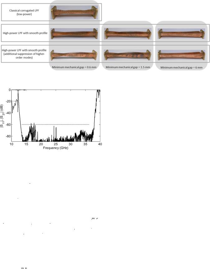
In order to prove the power-handling capability of the filters designed with the method proposed in this paper, multipactor measurements have been performed at the European High Power RF Space Laboratory of the European Space Agency—Val Space Consortium (ESA-VSC). Specifically, we have tested the filters depicted in Fig. 9: i) a classical E-plane corrugated filter designed with FEST3D [22]; ii)
ARREGUI et al.: HIGH-POWER LOW-PASS HARMONIC FILTERS |
4381 |
Fig. 9. Test campaign: seven prototypes specifications for the fundamental 


have been designed and fabricated to measure their power-handling capability. All devices feature the same frequency mode.
Fig. 10. |
|
Measured frequency response of the |
|
|
|
|
|
|
|
mode for the classical |
||||||||||||||||||||||||||||||||||||
|
|
|||||||||||||||||||||||||||||||||||||||||||||
E-plane corrugated filter fabricated for the multipactor test campaign. |
|
|
|
|
|
|
|
is |
||||||||||||||||||||||||||||||||||||||
given in dashed line and |
|
|
|
|
|
|
|
|
|
in solid line. The frequency specification |
|
|
|
mask |
||||||||||||||||||||||||||||||||
for |
|
|
|
|
|
|
|
|
|
and |
|
|
|
|
|
|
|
|
|
is also |
|
|
given in dotted line. |
|
|
|
|
|
|
|
|
|
|
|
|
|
|
|
|
|||||||
three low-pass filters with different minimum mechanical
gaps ( |
|
|
|
|
|
|
|
|
|
|
|
|
|
|
|
, 1.5 mm, and 6 mm) for the sup- |
|
|
|
|
|
|
|
|
|
|
|||||||
pression of the |
|
|
|
|
|
mode designed following [5]; and iii) |
||||||||||
|
|
|
|
|
||||||||||||
|
|
|
|
|
||||||||||||
|
|
|
|
|
|
|
|
|
|
|
|
|
|
|
|
|
three low-pass filters with different minimum mechanical gaps
( |
|
|
|
|
|
|
|
|
|
|
|
|
|
|
|
, 1.5 mm, and 6 mm) for the suppression of |
|
|
|
|
|
|
|
|
|
|
|||||||
the |
|
|
|
|
|
|
and higher-order modes designed using the method |
|||||||||
|
|
|
|
|
|
|||||||||||
|
|
|
|
|
|
|||||||||||
|
|
|
|
|
|
|
|
|
|
|
|
|
|
|
|
|
proposed in Section II.
Considering the facilities of the ESA-VSC laboratory, the devices are designed to feature a pass band between 


|
|
|
|
|
|
|
|
|
|
and |
|
|
|
|
|
|
|
|
|
|
|
|
|
|
|
|
|
|
|
|
|
|
|
|
|
|
|
with a return loss better |
|||||||||||||||||||||
|
|
|
|
|
|
|
|
|
|
||||||||||||||||||||||||||||||||||||||||||||||||||
|
|
|
|
|
|
|
|
|
|
||||||||||||||||||||||||||||||||||||||||||||||||||
than 20 dB and 60 dB rejection level from |
|
|
|
|
|
|
|
|
|
|
|
|
|
|
|
|
|
|
|||||||||||||||||||||||||||||||||||||||||
and up to |
|
|
|
|
|
|
|
|
|
|
|
|
|
|
|
|
|
|
|
|
|
|
|
|
|
|
(third harmonic). Moreover, |
||||||||||||||||||||||||||||||||
since the classical corrugated filter needs a minimum mechanical gap equal of 0.6 mm to reject the frequencies up to the third harmonic, this value has been also used in the examples of our devices with smooth profile. This will prove the intrinsic benefits for high-power applications of simply using smooth patterns. Moreover, since our design method is not restricted to small gaps, 
 will be made larger. In particular, two other
values of minimum mechanical gap (1.5 mm and 6 mm) have been also used and the RF power threshold of the resulting filters compared. The measured frequency responses of the filters are depicted in Fig. 10–Fig. 12.
A. Multipactor Estimation
In order to estimate the power-handling capability of the designed devices, two approaches have been followed: a method based on the parallel-plate waveguide model [23], and the PIC software tool SPARK3D. The method based on the parallelplate waveguide model provides an estimation of the RF input power threshold that is, in many occasions, very conservative and restrictive. This is due to the fact that the infinite parallelplate approach results in the worst scenario possible, just providing the lowest RF breakdown power threshold. For the calculation of the RF input power threshold, the most critical gap region (where the maximum electric field occurs) must be identified in each filter. Next, the minimum RF input power threshold is calculated in this critical area at the highest operation frequency. For such purpose, we have used copper as conductor. We get similar values in all devices with a minimum mechanical gap of 0.6 mm: 190 W for the classical corrugated filter, 140 W for the low-pass filter with 


 -mode suppression designed following [5], and 210 W for the novel low-pass filter with


 and all higher-order mode suppression. When the minimum mechanical gap of the devices with smooth profile is increased, the values predicted are higher (see Table III). If the real electromagnetic field distribution inside the microwave device is considered, it will lead to a more accurate multipactor analysis. By means of the SPARK3D simulator tool and making use of the full-wave electromagnetic software CST MWS to obtain the electromagnetic field distribution, estimations of the power-handling capability of the filters have been performed. In this case, a value of 260 W has been obtained for the classical corrugated filter, whereas much larger values are estimated for the filters with smooth profile and the same minimum mechanical gap: 4300 W for the low-pass filter designed following [5] with only


 -mode suppression, and 5600 W for the novel low-pass filter with


 and all higher-order mode suppression. Therefore, in light of the comparison between the results of the parallel-plate model approach and SPARK3D, it is apparent the importance of considering the real geometry of the device in the high-power analysis of this kind of filters. Moreover, the PIC tool results show the high improvement that is achieved in the multipactor threshold level if smooth profiles

4382 |
IEEE TRANSACTIONS ON MICROWAVE THEORY AND TECHNIQUES, VOL. 61, NO. 12, DECEMBER 2013 |
Fig. 11. Measured frequency response of the |
|
|
|
|
|
|
|
|
|
mode for the low-pass fil- |
||||||||||||||||||||||||||||||||||||||||||||||||||||||||||||||||
|
|
|
||||||||||||||||||||||||||||||||||||||||||||||||||||||||||||||||||||||||
ters designed following [5]: a) |
|
|
|
|
|
|
|
|
|
|
|
|
|
|
|
|
|
|
|
|
|
, b) |
|
|
|
|
|
|
|
|
|
|
|
|
|
|
|
|
|
|
|
|
|
|
|
|
|
, and |
||||||||||||||||||||||||||
c) |
|
|
|
|
|
|
|
|
|
|
|
|
. |
|
|
|
|
|
|
|
|
|
is given in dashed line and |
|
|
|
|
|
|
|
|
|
|
|
|
|
|
|
in solid line. The |
|||||||||||||||||||||||||||||||||||
frequency specification mask for |
|
|
|
|
|
and |
|
|
|
|
|
|
|
is also given in dotted line. |
||||||||||||||||||||||||||||||||||||||||||||||||||||||||||||
|
|
|
|
|
|
|
|
|
|
|
|
|
|
|
|
|
|
|
|
|
|
|
|
|
|
|
|
|
|
|
|
|
|
|
|
|
|
|
|
|
|
|
|
|
|
|
|
|
|
|
|
|
|
|
|
|
|
|
|
|
|
|
|
|
|
|
|
|
|
|
|
|
|
|
Fig. 12. Measured frequency response of the |
|
|
|
|
|
|
|
|
|
|
mode for the low-pass fil- |
|||||||||||||||||||||||||||||||||||||||||||||||||||||||
|
|
|
|
|||||||||||||||||||||||||||||||||||||||||||||||||||||||||||||||
ters designed following the method proposed in Section II: a) |
|
|
|
|
|
|
|
|
|
|
|
|
|
|
|
|
|
, |
||||||||||||||||||||||||||||||||||||||||||||||||
|
|
|
|
|
|
|
|
|
|
|
||||||||||||||||||||||||||||||||||||||||||||||||||||||||
b) |
|
|
|
|
|
|
|
|
|
|
|
|
|
|
, and c) |
|
|
|
|
|
|
|
|
|
|
|
|
|
|
. |
|
|
|
|
|
|
|
|
|
is given |
in |
dashed line and |
||||||||||||||||||||||||
|
|
|
|
|
in solid line. The frequency specification |
|
mask for |
|
|
|
|
|
|
and |
|
|
|
|
|
is also |
||||||||||||||||||||||||||||||||||||||||||||||
|
given |
in dotted line. |
|
|
|
|
|
|
|
|
|
|
|
|
|
|
|
|
|
|
|
|
|
|
|
|
|
|
|
|
|
|
|
|
|
|
|
|
|
|
|
|
|
|
|
|
|
|
|
|
|
|||||||||||||||
are used, even maintaining the small minimum mechanical gap of the classical alternatives. Finally, when the filters with larger minimum mechanical gaps are analyzed with the PIC software tool, very high values are predicted, such as 15 kW for the filter designed following the method proposed in this paper with a minimum mechanical gap equal to 6 mm.
B. High-Power Measurements
In order to validate the simulation results, multipactor tests have been performed at the ESA-VSC laboratory by means of the test bed described in [20]. Several multipactor detection methods have been used: electron probe, nulling of the forward/reverse power at the carrier frequency, and second harmonic detection.
In order to have enough electrons in the critical gap area, a beta emitting radioactive source was placed near the device under test (DUT) aiming at the most critical areas, and an optical fiber connected to an ultraviolet lamp was also used (for photo-elec- tron emission). Moreover, the following parameters have been employed during the multipactor test: operation frequency equal to 12.1 GHz, pressure lower than 


 , ambient temperature, pulse width of 20
 , and pulse duty cycle equal to 2%.
For the classical corrugated filter, no events were observed up to 210 W, when the discharge occurred. It was detected by the nulling system, the electron monitoring, and also the harmonic detection system. When the low-pass filters designed following [5] or following the technique proposed in this paper

ARREGUI et al.: HIGH-POWER LOW-PASS HARMONIC FILTERS |
4383 |
Fig. 13. Schematic of the RF breakdown test bed configuration including the ring resonator.
were tested, no discharge was observed up to the maximum power provided by the amplifier (5.5 kW). Therefore, a ring resonator or travelling wave resonator was designed [24]–[26] and integrated into the test bed explained in [20], giving rise to the test bed configuration depicted in Fig. 13 and Fig. 14. The ring resonator permits to reinforce the field levels of the travelling wave created in the ring structure, which includes the critical gap area of the DUT. This allows us to increase the field levels inside the device and perform the multipactor tests at larger values than the one provided by the Travelling Wave Tube Amplifier (TWTA), making possible to fully characterize the filters with smooth profile. In the design of the ring resonator, three issues had to be taken into account:
1)The length of the ring should be an integer number of times the wavelength at the operation frequency (12.1 GHz). This ensures that the wave entering the ring and the wave that is propagating along it add in phase. This is guaranteed by including a phase shifter in the set-up.
2)The coupling to the ring should be variable to compensate for losses in the ring and control the magnitude of the wave travelling along it. Therefore, a variable directional coupler, which consists of two directional couplers and a phase shifter, has been employed.
3)A method to match out any backward wave should be provided [27]. In this case, two waveguide transformers have been used at the input and output of the DUT.
As it can be seen in Table III, although the high-power measurements coincides with the value estimated by the parallelplate model for the classical corrugated filter, the differences are very large in the devices with smooth profile. However, the multipactor discharges occurred at similar values to the ones predicted with the PIC software tool in all cases. This confirms that the smoothness of our filters has far reaching implications in terms of high-power and that the real geometry has to be considered for reliable multipactor estimations. Moreover, these results also confirm the high power-handling capability of the devices with smooth profile designed following [5] for the suppression of the fundamental 


 mode as well as of the novel filters proposed in this paper for the suppression of the higher-order modes too, even using very small minimum mechanical gaps. Finally, unlike classical design methods, our method is not restricted to the use of small minimum mechanical gaps, and the power-handling capability is even higher using larger mechanical gaps.
Fig. 14. Photographs of the Ku-band multipactor test bed including the ring resonator: (a) detail inside the vacuum chamber and (b) whole test bed.
TABLE III
HIGH-POWER RESULTS [W]
V. CONCLUSION
A method to design high-power low-pass filters with a wide spurious-free frequency response has been presented. These filters also achieve the suppression of all the higher-order (both 

 and non-

 ) modes in the rejected band. Due to the smooth profile of the novel devices, much higher multipactor threshold values have been obtained for our filters, even using the same minimum mechanical gap as their classical counterparts. Moreover, our method is actually not restricted to the small minimum gaps of the classical alternatives, since this is an independent parameter in our design process. Thus, for the same stringent specifications, the gap of our devices can be much larger than the one needed in classical filters. This provides even

4384 |
IEEE TRANSACTIONS ON MICROWAVE THEORY AND TECHNIQUES, VOL. 61, NO. 12, DECEMBER 2013 |
more possibilities to increase the high-power handling capabilities of our filters as we have shown with our measurement campaign at the ESA-VSC laboratory.
ACKNOWLEDGMENT
The authors would like to thank the second tier partnership program of the ESA-VSC European High Power RF Space Laboratory and its staff for the high-power measurements in the paper.
REFERENCES
[1]R. Levy, “Tapered corrugated waveguide low-pass filters,” IEEE Trans. Microw. Theory Tech., vol. 21, no. 8, pp. 526–532, August 1973.
[2]R. J. Cameron, C. M. Kudsia, and R. R. Mansour, Microwave Filters for Communications Systems: Fundamentals, Design, Applications. Hoboken, NJ, UDS: Wiley, 2007.
[3]I. Arnedo, J. Gil, N. Ortiz, T. Lopetegi, M. A. G. Laso, M. Sorolla, M. Thumm, D. Schmitt, and M. Guglielmi, “Ku-band high-power lowpass filter with spurious rejection,” Electron. Lett., vol. 42, no. 25, pp. 1460–1461, Dec. 2006.
[4]I. Arregui, I. Arnedo, A. Lujambio, M. Chudzik, M. A. G. Laso, T. Lopetegi, and M. Sorolla, “Design method for satellite output multiplexer low-pass filters exhibiting spurious-free frequency behavior and high-power operation,” Microw. Opt. Technol. Lett., vol. 52, no. 8, pp. 1724–1728, Aug. 2010.
[5]I. Arregui, I. Arnedo, A. Lujambio, M. Chudzik, D. Benito, R. Jost, F.-J. Görtz, T. Lopetegi, and M. A. G. Laso, “A compact design of high-power spurious free low-pass waveguide filters,” IEEE Microw. Wireless Compon. Lett., vol. 20, no. 11, pp. 595–597, November 2010.
[6]I. Arregui, I. Arnedo, T. Lopetegi, M. A. G. Laso, and A. Marcotegui, “Low-Pass Filter for Electromagnetic Signals,” U.S. Patent US 2010/ 0308938, European Patent EP 2 244 330, Jan. 21, 2008.
[7]G. F. Craven, “Waveguide bandpass filters using evanescent modes,” Electron. Lett., vol. 2, no. 7, pp. 251–252, July 1966.
[8]G. F. Craven and C. K. Mok, “The design of evanescent mode waveguide bandpass filters for a prescribed insertion loss characteristic,” IEEE Trans. Microw. Theory Tech., vol. 19, no. 3, pp. 295–308, March 1971.
[9]R. V. Snyder, “New application of evanescent mode waveguide to filter design,” IEEE Trans. Microw. Theory Tech., vol. 25, no. 12, pp. 1013–1021, Dec. 1977.
[10]H. F. Chappelle, “Waveguide low pass filters using evanescent mode inductors,” Microw. J., vol. 2A, no. 12, pp. 71–72, Dec. 1978.
[11]A. M. K. Saad, “Novel harmonic filters for satellite application,” in Proc. IEEE MTT-S Digest, San Francisco, CA, USA, 1984, pp. 292–294.
[12]G. Matthaei, L. Young, and E. M. T. Jones, Microwave Filters, Impedance-Matching Networks, Coupling Structures. Norwood, MA, USA: Artech House, 1980.
[13]F. Arndt, R. Beyer, W. Hauth, D. Schmitt, and H. Zeh, “Cascaded wide stop band waffle-iron filter designed with a MM/FE CAD method,” in
Proc. Eur. Microw. Conf. (EuMC 1999), Munich, Germany, Oct. 2005, pp. 186–189.
[14]M. B. Manuilov and K. V. Kobrin, “Field theory CAD of waffle-iron filters,” in Proc. Eur. Microw. Conf. EuMC, Munich, Germany, Oct. 1999, pp. 1227–1230.
[15]I. Arregui, F. Teberio, I. Arendo, A. Lujambio, M. Chudzik, D. Benito, R. Jost, F.-J. Görtz, T. Lopetegi, and M. A. G. Laso, “High-power low-
pass harmonic waveguide filter with 


 -mode suppression,” IEEE Microw. Wireless Compon. Lett., vol. 22, no. 7, pp. 339–341, Jul. 2012.
[16]F. De Paolis, R. Goulouev, J. Zheng, and M. Yu, “CAD procedure for high-performance composite corrugated filters,” Trans. Microw. Theory Tech., vol. 61, no. 9, pp. 3216–3224, September 2013.
[17]R. Levy, “Inhomogeneous stepped-impedance corrugated waveguide low-pass filters,” in Proc. IEEE MTT-S Digest, 2005, pp. 123–126.
[18]M. Yu, “Power-handling capability for RF filters,” IEEE Microw. Mag., vol. 8, no. 5, pp. 88–97, Oct. 2007.
[19]J. Vaughan, “Multipactor,” IEEE Trans. Electron Devices, vol. 35, pp. 1172–1180, Jul. 1988.
[20]I. Arregui, F. Teberio, I. Arnedo, A. Lujambio, M. Chudzik, D. Benito, T. Lopetegi, R. Jost, F.-J. Görtz, J. Gil, C. Vicente, B. Gimeno, V. E. Boria, D. Raboso, and M. A. G. Laso, “Multipactor-resistant lowpass harmonic filters with wide-band higher-order mode suppression,” presented at the IEEE Int. Microw. Symp. Digest, Seattle, WA, USA, Jun. 2013.
[21]K.-L. Wu and G. McDonald, “Coping with hidden spurious harmonic modes in the design of low pass corrugated waveguide filters,” Microw. J., vol. 44, no. 11, pp. 180–183, Nov. 2001.
[22]O. Monerris, P. Soto, S. Cogollos, V. E. Boria, J. Gil, C. Vicente, and B. Gimeno, “Accurate circuit synthesis of low-pass corrugated waveguide
filters,” in Proc. Eur. Microw. Conf. (EuMC 2010), Paris, France, Oct. 2010, pp. 1237–1240.
[23]P. Sarasa, A. González, H. Esteban, P. Mader, K. Tossou, and P. Lepeltier, “Comparative study of the power handling capability of space broadband antenna filters in Ku-band,” in Proc. 5th ESA Int. Workshop Multipactor, Corona and Passive Intermodulation in Space RF Hardware, Noordwijk, Sep. 12–14, 2005.
[24]F. J. Tischer, “Resonant properties of ring circuits,” IRE Trans. Microw. Theory Tech., vol. 5, no. 1, pp. 51–56, Jan. 1957.
[25]L. J. Milosevic and R. Vautey, “Traveling wave resonators,” IRE Trans. Microw. Theory Tech., vol. 6, pp. 136–143, Apr. 1958.
[26]S. J. Miller, “The travelling wave resonator and high power microwave testing,” Microw. J., vol. 9, no. 3, pp. 50–68, Sep. 1960.
[27]K. Tomiyasu, “Effect of a mismatched ring in a travelling-wave resonant circuit,” IRE Trans. Microw. Theory Tech., vol. 5, no. 4, p. 267, Oct. 1957.
Ivan Arregui (S’08–M’12) received the Telecommunication Engineering, M.Sc. and Ph.D degrees from the Public University of Navarre, Navarre, Spain, in 2005, 2008, and 2013, respectively.
He is currently an Assistant Professor in the Electrical and Electronic Engineering Department of the Public University of Navarre. His research interests include periodic structure devices for microwave, millimeter wave and terahertz frequency ranges, numerical techniques for the inverse scattering synthesis, and design of passive components for
communications satellites.
Dr. Arregui was the recipient of a grant from the Spanish Ministry of Science and Innovation and is cofounder of the spin-off company TAFCO Metawireless.
Fernando Teberio received the Telecommunication Engineering degree and the M.Sc. degree from the Public University of Navarre, Navarre, Spain, in 2009 and 2011, respectively. He is currently working towards the Ph. D. degree at the Electrical and Electronic Engineering Department of the Public University of Navarre.
His research interests include periodic structure devices and design of passive components for communications satellites.
Israel Arnedo (S’05–M’11) was born in Tudela, Navarre, Spain, in 1980. He received the Telecommunication Engineering, M.Sc., and Ph.D. degrees from the Public University of Navarre, Pamplona, Spain, in 2004, 2007, and 2010, respectively.
He is currently an Assistant Professor with the Electrical and Electronic Engineering Department, Public University of Navarre, where he has collaborated in research projects supported by the Spanish Government, the Natural Sciences and Engineering Research Council of Canada (NSERC), and the
European Commission. He is cofounder of the spin-off company TAFCO Metawireless. He is a Reviewer for several international scientific journals. His research interests of the microwave, millimeter-wave, and terahertz fields include periodic structure devices, coupled-mode theory, inverse-scattering synthesis, and their applications in ultra-wideband (UWB) systems, space and satellite technology, and biomedical engineering research.
Dr. Arnedo was the recipient of a Formación de Profesorado Universitario (FPU) grant of the Spanish Ministry of Education and Science to support his doctoral research. In 2012 he was awarded with a José Castillejo grant of the Spanish Ministry of Education to support his postdoctoral research stay at the Institut d’Électronique de Microélectronique et de Nanotechnologie (IEMN), Villeneuve D’Ascq, France.

ARREGUI et al.: HIGH-POWER LOW-PASS HARMONIC FILTERS
Aintzane Lujambio was born in San Sebastián (Guipúzcoa), Spain in 1982. She received the Telecommunication Engineering degree and M.Sc. degree from the Public University of Navarre, Navarre, Spain, in 2006 and 2010, respectively, and is currently working toward the Ph.D. degree in electrical and electronic engineering at the Public University of Navarre.
She is currently working as a researcher with the Electrical and Electronic Engineering Department, Public University of Navarre. She has collaborated
in research projects supported by the Spanish Government and the European Commission. Her research interests include algorithms for microwave filter design, inverse-scattering synthesis methods and UWB systems.
Magdalena Chudzik (S’08) was born in Warsaw, Poland, in 1984. She received the B.Sc. and M.Sc. degrees in electrical and computer engineering from the Warsaw University of Technology, Warsaw, Poland, in 2007 and 2009, respectively. Currently she is working toward the Ph.D. degree at the Electrical and Electronic Engineering Department of the Public University of Navarre, Spain.
Her research interests include coupled-mode theory, periodic structure devices, and passive devices in microwave, millimeter-wave and terahertz
technologies.
Mrs. Chudzik was the recipient of a Formación de Profesorado Universitario (FPU) grant from the Spanish Ministry of Education and Science to support her doctoral research.
David Benito was born in Huesca, Spain, in 1965. He received the M.Sc. and Ph.D. degrees in electrical engineering from the Polytechnic University, Madrid, Spain, in 1992 and 1999, respectively.
Since 1992, he has been an Associate Professor, and since 2010 he is Full Professor, both at the Electrical Engineering Department of the Public University of Navarre in Spain. His main research interests include the analysis/synthesis techniques of photonic/electromagnetic-bandgap structures and microwave/photonic metamaterials, and their
applications to microwave and photonics communication subsystems. He has authored or coauthored over 80 international papers and conference contributions. He has coordinated several research projects supported by the Spanish Government and European Union concerning fiber-optic communications and microwave engineering. He is also co-founder of the spin-off company Tafco Metawireless S.L.
Txema Lopetegi (S’99–M’03) was born in Pamplona, Navarre, in 1973. He received the M.Sc. and Ph.D. degrees in telecommunication engineering from the Public University of Navarre, Navarre, Spain, in 1997 and 2002, respectively.
Since 1997 he has been with the Electrical and Electronic Engineering Department, Public University of Navarre, first as Assistant Professor and since 2006 as Associate Professor. In 1999 and 2000, he was awarded a grant from the Spanish Ministry of Education to support the research in his doctoral
thesis. During 2002 and 2003 he was with the Payload Systems Division, European Space Research and Technology Center (ESTEC), European Space Agency (ESA), at Noordwijk, The Netherlands, as post-doctoral researcher. He is also co founder of the spin off company TAFCO Metawireless. His current research interests include metamaterials and synthesized structures in microwave and THz technologies, as well as coupled mode theory and synthesis techniques using inverse scattering.
4385
Rolf Jost was born in 1952 in Mönchengladbach, Germany. He received his Diploma in Physics from the University of Stuttgart, Stuttgart, Germany, in 1986.
From 1986 to 2000 he was responsible for the development of passive microwave components for space application at ANT Nachrichtentechnik respectively at Bosch Telecom GmbH Backnang, Germany. Since 2001 he is program manager for the design and development of active and passive microwave equipment for space at TESAT Spacecom
GmbH in Backnang, Germany.
Franz-Josef Görtz was born in Hückelhoven, Germany, on October 08, 1954. He received the degree in electrical engineering Dipl.-Ing. (TH) from the Technical University RWTH Aachen, Germany, in 1982.
He is currently with Tesat-Spacecom GmbH & Co. KG, before Bosch Satcom, ANT Nachrichtentechnik, ATN and AEG-Telefunken, involved in development of passive products, filters and multiplexers. Since 1982 he designed, developed and implemented microwave flight hardware for several satellite programs covering L- to Ka-band
frequencies. Actually he is working on input multiplexers for Ka-Band and his special interest is computer aided modelling, design and tuning of microwave filters. He has authored or coauthored several papers in technical journals and conferences and holds 5 patents in the area of microwave filters and multiplexers.
Jordi Gil received the Licenciado degree in physics from the Universidad de Valencia, Spain, in 2000, and the Ph.D. degree in telecommunications engineering from the Universidad Politécnica de Valencia, Valencia, Spain, in 2010.
From 2001 to 2004, he was Researcher with the Aerospatiale Italian Company, Ingegneria Dei Sistemi-S.p.A., under the frame of the V European Framework Programme. From 2004 to 2006, he joined the Microwave Applications Group, Universidad Politécnica de Valencia, under the frame
of a European reintegration grant funded by the VI European Framework Programme. In 2006, he cofounded the company Aurora Software and Testing S.L. which is devoted to the space sector. He is currently the Managing Director of the company, where he also continues his research activities. His current research interests include numerical methods in computer-aided techniques for the analysis of microwave and millimeter passive components based on waveguide technology, and nonlinear phenomena appearing in power microwave subsystems for space applications.
Dr. Gil was awarded in 2011 with the Ph.D. Thesis Extraordinary Award at the Universidad Politécnica de Valencia.
Carlos Vicente was born in Elche, Spain, in 1976. In 1999, he received the Dipl. degree in physics from the University of Valencia, Valencia, Spain, and the Dr.-Ing degree in Engineering in 2005 from the Technical University of Darmstadt, Germany.
From 1999 until the beginning of 2001, he worked as a Research Assistant at the Department of Theoretical Physics of the University of Valencia. From 2001 until 2005 he was Assistant Professor at the Institute of Microwave Engineering at the Technical University of Darmstadt. From 2005 he is with the Mi-
crowave Applications Group, from the Technical University of Valencia, Spain. In 2006, he co-founded the company Aurora Software and Testing S. L. devoted to the telecommunications sector. His research concerns the analysis and design of passive components for communications satellites with special emphasis in high power practical aspects such as Passive Intermodulation, Corona Discharge and Multipaction.