

диафрагмированные волноводные фильтры / b3654f4f-bfea-4a4a-b04b-55b145da8db2
.pdfJOURNAL OF AERONAUTICAL MATERIALS |
Vol. 43, Issue-01, 2023 |
ISSN: 1005-5053 |
pp. 411-418 |
|
DESIGN AND ANALYSIS OF A COMPACT FILTENNA FOR BLUETOOTH, WI-
MAX, WLAN & 5G-MID BAND APPLICATIONS
B. Ramesh1, K. Koteswara Rao2, K.P. Vinay3, K. Hema Divya4, G. Deepika5, M.K.
Prudhvi6, D.S. Vaishnavi7
1Ph. D Scholar, School of Electronics, KIIT University, Bhubaneswar, Odessa 1,2Assistant Professor, Dept. of ECE Raghu Engineering College, Dakamarri, Andhra Pradesh
3Professor, Dept. of ECE, Raghu Engineering College, Dakamarri, Andhra Pradesh 4, 5, 6&7Student, Dept. of ECE, Raghu Engineering College, Dakamarri, Andhra Pradesh
Abstract: In order to provide an efficient, low cost, and small size radiating structure that passes a certain frequency band with negligible amount of interference, the combination of filters and antennas isproposedtoformasingle elementcalledfiltenna.Toenhancetheoverall system performancebyreducing theimpedancemismatch,circuit size,losses,etc., theantenna and the filter could be integrated. The integrated device will serve as a multi-function module that performs, simultaneously, filtering and radiating functions is called filtenna. This combination filter and antenna achieves many important advantages of wide bandwidth, small electrical size and an improved performance for frequency selectivity. This paper presents a filtenna element with compact size that can radiate in the frequency range (1.9-5.5 GHz). The proposed filtenna radiates in the 5G mid band frequency range (3.6 GHz) and perfectly rejects all the frequenciesoutsidethisrange.The filtenna iscomposed ofa printed circuit antenna that is terminated with a crescent shaped stub that is coupled electromagnetically with a miniaturizedsharpband-passfilter.Moreover,thestructurehasanomnidirectionalpatternwith reasonable gain value within the band of interest, and this makes the antenna very suitable for portable 5G devices.
KEYWORDS: band-pass, dual-band, filtenna, monopole antenna.
I.INTRODUCTION
In the field of communication systems, whenever the need for wireless communication arises, thereoccursthe necessityofanantenna. Antenna hasthe capabilityofsendingorreceiving the electromagnetic waves for the sake of communication, where you cannot expect to lay down a wiring system. Antenna is the key element of this wireless technology.[1] Antennas have undergone many changes, in accordance with their size and shape. There are many types of antennas depending upon their wide variety of applications.[2] hexagon slotted circular monopole antenna [3], 9-shaped monopole antenna [4], star shaped antenna [5], dumbbell shapedslot antenna[6].Each shapecan beusedfor differentapplicationslikeSingle-band[7], [8], dual band [9], and single-dual band [10]. However, given the nature of most bands and extent interferers, antennas need a tight controller to suppress the interference and to eliminate the unwanted signals where other system exists.
The filtenna is a special device whose distinguishing feature provides a complete or partial suppression of some aspects of the signal, that is, the removal of some undesired frequencies orfrequencybands.Itismodifiedtocovertheintendedrangbyusingmany techniquesofstubloaded multiple mode resonator [11], This combination (Filter + antenna) achieves many
411

DESIGN AND ANALYSIS OF A COMPACT FILTENNA FOR BLUETOOTH, WI-MAX, WLAN & 5G-MID BAND APPLICATIONS
important advantages of wide bandwidth, small electrical size, and an improved performance for frequency selectivity. There are several technics to give filtering antenna, of two edgecoupled filters andtwo hairpinfilters [12],a C-shaped narrow band resonator and an E-shaped wideband resonator [13], and customdesigned coupling probe structures [14], a pair of parasitic elements and pair of slits [15-16]. This new filtering antenna combination is called Filtenna.
In this paper, a compact and sharp printed circuit filter is combined with a printed circuit antenna that is terminated with a crescent shaped stub to form a filtenna with large selectivity. The resulted filtenna perfectly covers the 5G mid-band that occupies the frequency range 3.6- 3.7 GHz and perfectly rejects all the frequencies outside the intended range of frequencies. Structure of a filtenna is designed by using coupled electromagnetically to the proposed antenna to attain the compactness in the structure. The simulation results verify the perfect frequency coverage for the 5G mid-band applications in term of the reflection coefficient and transmissioncoefficient. In addition, the results also show an omnidirectional radiation pattern with reasonable gain value. It is clear that the current is mainly concentrated over all antenna arms and the top part of CLL element at 3.6GHz. The omnidirectional radiation pattern of the proposed design and its compact size make the filtenna to be a superior selection for portable 5G mid-band gadgets.
II.FILTENNA DESIGN
The design of the proposed filtenna is described in this section. The main design goals are: inserting a filtering element that determines the operation frequency range of the antenna with highselectivity, providinga flat gain, and providinggoodradiationpattern characteristics.The designstructureconsistsoftwo-squareCapacitivelyLoadedLoop(CLL)Basedbandpassfilter similar to that presented in [21]. The composite design is depicted in Fig. It is printed on a Rogers RT5880 substrate with dielectric constant ( ) of 2.2, a loss tangent (δ) of 0.009 and thickness (h) of 0.8 mm, and half ground, and overall size 27 mm*24.2 mm as demonstrated in Fig. The design starts with a circular monopole antenna, then it is modified to moon shaped radiatingantennaat 3.6 GHzwithradiusof (R).Byreplacingthe second halfoftheCLL based filter with antenna as a parasitic element, the proposed filtenna is presented. It is fed by a 50 Ω microstrip feed line whose characteristic impedance is given by the following formula [1]:
= |
(1) |
. |
|
Where, pdenotesthewidthofthefeedline,and is theheightofthesubstrate.Theelectrical length of the monopole antenna with respect to the centre frequency [22]:
= |
= |
(2) |
|
|
|
= + |
1+12 |
(3) |
d is the effective dielectric constant of monopole antenna. The optimized parameters of the proposed filtenna are given in Table 1:
412

DESIGN AND ANALYSIS OF A COMPACT FILTENNA FOR BLUETOOTH, WI-MAX, WLAN & 5G-MID BAND APPLICATIONS
(a) Top View (b) Bottom View
Fig.1. Geometry of Proposed Filtenna
Table 1 The Optimized Design Parameters of the Presented Filtenna.
Parameter |
Dimensions(mm) |
Parameter |
Dimensions (mm) |
L |
24.2 |
He |
2.01 |
W |
27 |
Pl |
8.65 |
H |
0.8 |
Pw |
8.65 |
R |
3 |
H1 |
6.04 |
D |
3.8 |
H2 |
5.09 |
Ha |
6.5 |
H3 |
3.8 |
Hb |
6.5 |
H4 |
8.65 |
Hc |
2.5 |
H5 |
5.65 |
Hd |
2.7 |
Lb |
13 |
III. RESULTS & DISCUSSION
The simulated reflection coefficients of the antenna with filter are shown in Fig.2. The proposed antenna has a bandwidth of 3.6 GHz (from 3.36 GHz to 4.2GHz). The filtenna (antenna with filter) shows dual resonant frequencies at 3.63GHz and 3.75 GHz, respectively. Two resonance frequencies are close to each other so that they show a broad bandwidth characteristic from 3.56GHz to 3.7GHz. It effectively suppresses the unwanted signals out of the 5G mid-band. In Fig. 3, the current distribution of the filtenna is shown in order to understand the radiation mechanism at each resonant frequency .It is clear that the current is mainlyconcentratedoverallantennaarmsandthetoppartofCLLelementat3.6GHzasshown in Fig. 3(a). On the other hand, Fig. 3(b) exhibits that the current is concentrated around the filterarms at 3.6 GHz and a negligible amount at the antenna because the frequency 3.7GHz is outside the bandwidth ofthe proposed filtenna. Inother words, outside the frequency coverage of the filtenna, the energy is stored within the filter rather than radiating via the antenna.
413
DESIGN AND ANALYSIS OF A COMPACT FILTENNA FOR BLUETOOTH, WI-MAX, WLAN & 5G-MID BAND APPLICATIONS
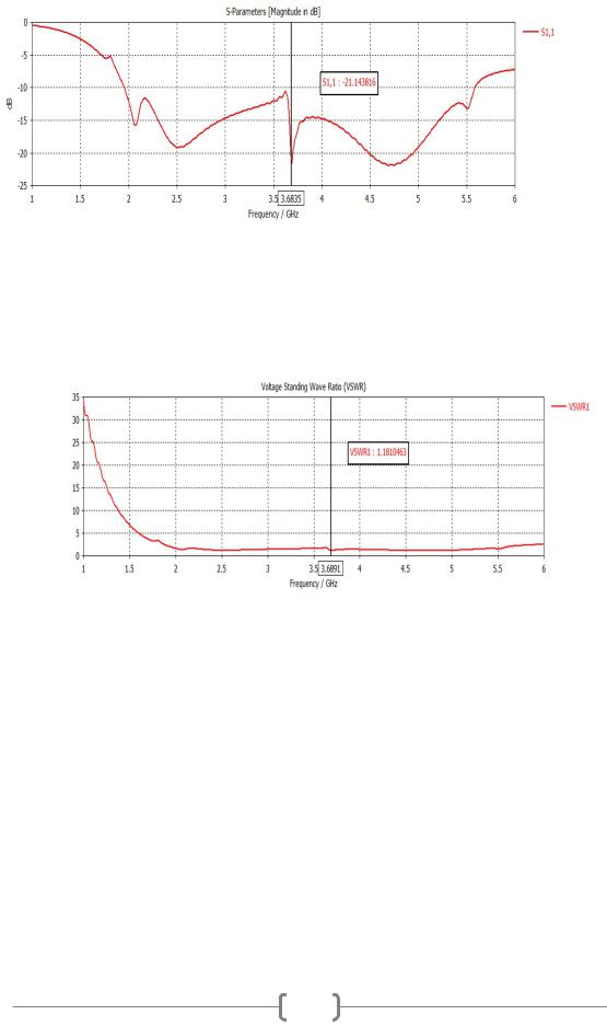
Fig. 2. Reflection coefficient plot of the proposed filtenna
In practice, the most commonly quoted parameter in regards to antennas is S11. S11 represents howmuchpoweris reflectedfromtheantenna,and henceisknownasthereflectioncoefficient (sometimes written as gamma: or return loss. If S11=0 dB, then all the power is reflected from the antenna and nothing is radiated. When connected to a network analyser, S measures the amount of energy returning to the analyser - not what's delivered to the antenna and the S11 value is -21.14dB as shown in fig. 2.
Fig. 3 VSWR plot of the proposed filtenna
Voltage standing wave ratio (VSWR) is defined as the ratio between transmitted and reflected voltagestandingwavesinaradiofrequency(RF)electricaltransmissionsystem.Itisameasure of how efficiently RF poweris transmitted from the power source, through a transmissionline, and into the load. The Voltage Standing Wave Ratio (VSWR) is an indication of the amount of mismatch between an antenna and the feed line connecting to it. This is also known as the Standing Wave Ratio (SWR). The range of values for VSWR is from 1 to ∞. A VSWR value under2isconsideredsuitableformostantenna applications.TheVSWR plotisshowninfig.3.
414

DESIGN AND ANALYSIS OF A COMPACT FILTENNA FOR BLUETOOTH, WI-MAX, WLAN & 5G-MID BAND APPLICATIONS
(a) at 3.6GHz
(b) at 3.7 GHz
Fig. 4. Surface current distribution (a) at 3.6GHz and (b) at 3.7 GHz.
The simulated 2D-polar power patterns of the filtenna at 3.7GHz are illustrated in Fig. 4. (a) and (b), respectively. It is clear that the filtenna provides good radiation characteristics with a bidirectional power pattern shape in the E-plane, a stable omnidirectional radiation patterns in H-plane, and gain value of 2.89 dBi.
(a)E-plane
415

DESIGN AND ANALYSIS OF A COMPACT FILTENNA FOR BLUETOOTH, WI-MAX, WLAN & 5G-MID BAND APPLICATIONS
E-Plane is always the plane that contains the electric component of the EM radiation and the direction of maximum radiation. The E plane will dictate whether the linear polarization is horizontal or vertical. In this arrangement when the elements are excited then maximal radiationemission occurs from the broadside (i.e., the direction normal tothe array axis) while the little amount of radiation is emitted from the other directions. Thereby providing a bidirectional radiation pattern. The reason for its bidirectional radiation pattern is that it radiates in both directions along the broadside.
(b)H-plane
This plane relates to the magnetic portion of the EM energy generated by a linearly polarized antenna. It will always be perpendicular to the E plane. In radio communication, an omnidirectional antenna is a classof antenna which radiates equal radio powerinall directions perpendicular to an axis (azimuthal directions), with power varying with angle to the axis (elevation angle), declining to zero on the axis. Especially in receiving or sending radio waves equally well in all directions. Omni-Directional antennas also work well when you are receiving from a signal that you are unsure where it originates because its signal is received from all angles Another great use is to broadcast a hotspot from a central area of a location such as a park, fairgrounds, backyard, etc...
(c)Both E&H-plane
Fig. 5. The E & H-plane far field radiation patterns
416

DESIGN AND ANALYSIS OF A COMPACT FILTENNA FOR BLUETOOTH, WI-MAX, WLAN & 5G-MID BAND APPLICATIONS
The E& H- Plane far field radiation patterns are shown in fig. 5(a), 5(b) & 5(c). The E-plane and H-plane are reference planes for linearly polarized waveguides, antennas and other microwave devices.
IV.CONCLUSION
A compact filtenna with sharp rejection capability of the non-desired radiation outside the 5G mid-band has successfully been designed. A printed circuit antenna is combined electromagneticallywithahalfCLLfiltertoformtheproposeddesign.Inspiteofitssmallsize (24.2 × 27 × 0.8 3), the filtenna matching and radiation characteristics are so suitable for radiating the 5G mid-band EM energy and suppressing the others that cause interference with them.The filtenna reflectioncoefficienthasreducedvaluesat the passband(3.6-3.7GHz)that reaches to less than -15dB. The omnidirectional radiation pattern of the proposed design and its compact size make thefiltenna to be a superior selection forportable 5G mid-bandgadgets.
REFERENCES
[1].C.A.Balanis,AntennaTheory:AnalysisandDesign,3rded.NewYork,NY,USA: Wiley, 2005.
[2].D. Sarkar, K.V. Srivastava, and K. Saurav, “Antenna for Cognitive Radio Applications,” IEEE Antennas and Wireless propagation litters, Vol. 13, pp. 396-399, 2014.
[3].T. Gayatri, N. Anvesh kumar, and V. Sharma, “A Hexagon Slotted Circular Monopole UWB AntennaforCognitiveRadioApplications,”2020NationalConferenceonEmerging Trends in Information Technology and Engineering (ic-ETITE), April. 2020.
[4].J. Panda, A. Saladi, and R. Kshetrimayum, “A Compact Printed Monopole Antenna for Dual-band RFID and WLAN Applications,” Radio engineering, Vol. 20, NO. 2, pp. 464467, June 2011
[5].S. Janjarla, B. Dasgupta,“ Star Shaped Broadband Printed Antenna with U-Shape Ground Plane,” 2020 National Conference on Emerging Trends on Sustainable Technology and Engineering applications (NCETSTEA), 18 June. 2020.
[6].T. Cheng, W. Jiang, S. Gong, and Y. Yu, “Broadband SIW Cavity-Backed Modified Dumbbell-Shaped Slot Antenna,” IEEE Antennas and Wireless propagation litters, Vol. 18, Issue. 5, pp. 936-940, May 2019.
[7].S. Ali, A. Reja, and Y. Hachim, “Design a Compact Wideband Antenna Used in Radio FrequencyIdentification Systems,”Iraqi Journal forElectricalandElectronicEngineering, pp. 134-138, June 2020. DOI: 10.37917/ijeee.sceeer.3rd.19.
[8].H. Kaur, and N. Ahuja, “Design of Single Band Slotted Microstrip Patch Antenna for WiMax Band,” International Journal of Computer Applications, Vol. 67, No. 14, pp. 4043, April 2013.
417

DESIGN AND ANALYSIS OF A COMPACT FILTENNA FOR BLUETOOTH, WI-MAX, WLAN & 5G-MID BAND APPLICATIONS
[9].R. Madina, E. Rahardjo, F. Zulkifli, “Multiband Wideband Monopole Antenna using RSRR for WLAN and WiMAX Applications,” 2019 IEEE Region 10 Humanitarian Technology Conference, 12-14 Nov.2019.
[10].M. Abdullah, and S. Koziel, “A Novel Versatile Decoupling Structure and Expedited Inverse-Mode – Based Re-Design Procedure for Compact Singleand Dual-Band MIMO Antennas,” IEEE Access, Vol. 9, pp. 37656-37667, March 2021.
[11].F. Alnahwi, Y. Al-Yasir, A. Abdulhameed, A. Abdullah, and R. Abd-Alhameed, “A Low-CostMicrowave Filterwith ImprovedPass band and Stop band CharacteristicsUsing Stub Loaded Multiple Mode Resonator for 5G Mid-Band Applications,” Electronics, Vol. 10, Issue. 4, February 2021.
[12].S. Lin, P. Chiou, Y. Chen, and S. Chang,“ An Accurate Filtenna Synthesis Approach Based on Load –Resistance Flattening and Impedance-Transforming TappedFeed Techniques, Vol. 6, pp. 24568-14581, 24. May 2018.
[13].L. Rodrigues, T. Varum, and J. Matos, “The Application of Reconfigurable Filtenna in Mobile Satellite Terminals“, IEEE Access, Vol. 8, pp. 77179-77189, 2020.
[14].M. Tang, Z. Wen, H. Wang, M. Li, and R. Ziolkowski, “A Compact, FrequencyReconfigurable Filtenna with Sharply Defined Wideband and Continuously Tunable Narrowband States,” IEEE Transactions on Antenna and Propagation, 23.June 2017.
[15].K.Hu,M. Tang,Y.Wang,D.Li,andM.Li,“ ACompact,Vertically IntegratedDuplex Filtenna With Common Feeding and Radiating SIW Cavities,” IEEE Transactions on Antennas and propagation , Vol. 69, Issue. 1, pp. 1-6, 2021.
[16].F. Juma'a, F. Alnahwi, “Design and Simulation ofButterfly-Shaped Filtenna with Dual Band Notch for Portable UWB Applications,” Iraqi Journal for Electrical and Electronic Engineering, Vol. 17, Issue 1, pp. 1-7, June 2021.
418