

диафрагмированные волноводные фильтры / ae0af001-6963-400d-9eeb-f1f8e0f47f5b
.pdfThis article has been accepted for publication in a future issue of this journal, but has not been fully edited. Content may change prior to final publication. Citation information: DOI 10.1109/TAP.2021.3070629, IEEE Transactions on Antennas and Propagation
1
High Selectivity and High Gain X-Band Waveguide Filtering Antenna Based on Triple-Mode Resonator
Kai-Ran Xiang, Fu-Chang Chen, Member, IEEE and Qing-Xin Chu, Fellow, IEEE
Abstract—In this paper, a high selectivity and high gain filtering slot antenna operating in X-band is designed based on a triple-mode cavity resonator. Three modes of the cavity resonator, namely, TE101, TE011, and TM110, are excited by properly selecting the position and size of the coupling aperture. By adjusting the frequency and external coupling of the three modes, transmission zero can be introduced on both sides of the passband, achieving high selectivity of antenna gain. Because the cavity has a high unload quality factor, the radiation efficiency in the passband is high and flat. In order to increase the gain of the filtering waveguide antenna, a grid-slotted patch is added on the top of the slot. To demonstrate the concept, an X-band waveguide filtering antenna is designed and fabricated. Measured results show the filtering antenna can obtain a gain of greater than 8.5 dBi in the frequency range of 9.8-10.2 GHz.
1
Index Term—Filtering antenna, high gain, high selectivity, rectangular cavity, slot, triple-mode resonator.
I. INTRODUCTION
MODERN WIRELESS communication system puts forward the requirement of high integration and multi-function for antenna design. Filtering antenna has attracted researchers’ attention due to its ability to reduce the loss of the matching network and reduce the complexity of filter circuit design.
A simple method is to cascade the antenna to the output port of the filter to design the filtering antenna [1]-[3]. Different filters, such as bandpass filter [1], band-notched filter [2], reconfigurable filter [3] and so on, are used to design antennas with different filtering functions. In [4]-[6], the bandpass filter or band-stop filter is integrated into the antenna feeding line, which reduces the size of the cascade structure. Although this cascade design method is simple, the inherent loss of the filter affects the radiation performance of the antenna. By taking the antenna equivalent to an RLC circuit as the last-stage resonator of bandpass filter, the filtering antenna is designed by using the method of bandpass filter synthesis theory [7]-[11]. Different filter design methods can be used to design different filtering antennas. By extracting the lumped parameters of the antenna, a filtering antenna array with third-order Chebyshev response is designed [7]-[8]. Filtering patch antenna with high selectivity [9], wide stopband suppression [10], and the duplex filtering waveguide antenna [11] can be designed by the method of filter synthesis. The co-design of the band-pass filter (BPF) and the antenna using bandpass filter synthesis theory can reduce the design of filter circuit and improve the filtering performance of antenna. In order to reduce circuit design, many methods of designing filtering antenna without additional circuit are proposed [12]-[13]. In [12], filtering antenna is designed by adding short-pins and a slot line on the patch to generate radiation nulls on both sides of the passband. Using parasitical element to generate radiation zeros is also a method to design filtering antenna without the additional circuit [13].
Because of the high unload quality factor of cavity resonator, the filtering antenna designed by cavity resonator has high radiation efficiency. In [14]-[19], the cavity resonator is used to design filtering
This work was in part by the National Natural Science Foundation of China under Grant 62022035, in part by the Guangdong Provincial Key R&D Programme under Grant 2020B010179002, and in part by the Guangdong Basic and Applied Basic Research Foundation under grant 2019B151502032.
The authors are with the School of Electronic and Information Engineering, South China University of Technology, Guangzhou 510640, China (e-mail: chenfuchang@scut.edu.cn).
Grid-slotted patch
Radiant slot
Nylon column
Triple-mode
resonator
Coupling slot
Feeding port
Fig. 1. Structure of the proposed filtering antenna.
antenna with different functions. A waveguide filtering antenna with low sidelobe is designed [14] and cavity resonators are used to design slot antenna and antenna arrays [15]-[17]. A triple-mode cavity resonator working in three modes (TE101, TE011, TM110) are used to design a dual-functional structure with the integration of bandpass filter and antenna [18] and a triple-band slot antenna [19], where the three modes used in [18]-[19] works in different bands. Additionally, the antenna designed with cavity resonator in [14]-[19] cannot generate transmission zeros to realize high selectivity.
In this paper, a waveguide filtering antenna operating in X-band is designed by a triple-mode cavity resonator. A third-order filtering antenna with two transmission zeros is designed using only one cavity, which realizes miniaturization and high selectivity. In order to increase the gain of the proposed antenna, a grid-slotted patch is used to change the phase of the spherical wavefront. Furthermore, different bandwidth can be realized by adjusting the coupling structure and the resonant frequency of each mode. The design procedure of the filtering antenna is analyzed in detail and the measurement results are in good agreement with the simulation ones.
II.ANTENNA STRUCTURE AND ANALYSIS
A.Structure of the designed antenna
The 3D structure of the designed waveguide filtering antenna is shown in Fig. 1. The proposed antenna mainly consists of a metallic waveguide filtering slot antenna and a grid-slotted patch. The feeding
0018-926X (c) 2021 IEEE. Personal use is permitted, but republication/redistribution requires IEEE permission. See http://www.ieee.org/publications_standards/publications/rights/index.html for more information.
Authorized licensed use limited to: Univ of Calif Santa Barbara. Downloaded on June 23,2021 at 12:59:11 UTC from IEEE Xplore. Restrictions apply.
This article has been accepted for publication in a future issue of this journal, but has not been fully edited. Content may change prior to final publication. Citation information: DOI 10.1109/TAP.2021.3070629, IEEE Transactions on Antennas and Propagation
c a
b
 y
y
x
z
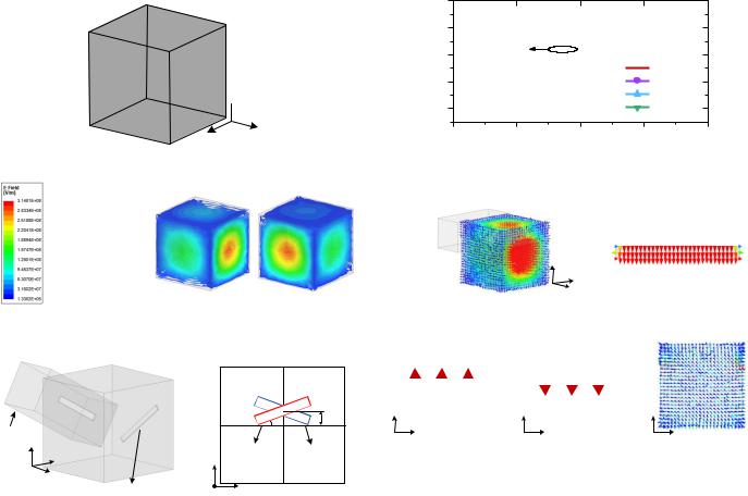
Fig. 2. Structure of the triple-mode cavity resonator.
(a) |
(b) |
(c) |
Fig. 3. Electric field distribution of the cavity resonator. (a) |
TE101 mode. (b) |
|
TE011 mode. (c) TM110 mode. |
|
|
|
|
a |
|
|
a |
|
|
|
|
|
|
|
|
|
|
|
|
|
|
w1 |
l1 |
l2 |
w2 |
|
|
|
|
|
θ |
|
s |
Port |
|
|
|
|
|
|
|
b |
|
|
|
|
|
|
|
|
|
|
|
|
|
b |
|
|
y |
|
|
Radiant slot |
|
||
|
x |
|
|
|
|||
|
z |
y |
|
|
|
|
|
|
|
|
|
|
|
||
|
c |
|
|
|
|
|
|
|
|
|
x |
|
|
|
|
|
|
Radiant slot |
z |
|
|
|
|
|
|
|
|
|
|
||
(a) (b)
Fig. 4. Structure of the filtering slot antenna. (a) 3-D structure. (b) Position and size of the radiant slot and the coupling slot.
port is a standard WR-90 waveguide. Except for the feeding port and grid-slotted patch, all structures are manufactured in aluminum, and the length and width of each part are both 40 mm. The upper part of the feeding port is a 40×40×5 mm3 cube structure, which is connected to the antenna structure. The lower part of the feeding port is a 41.4×41.4×5 mm3 cube structure, which is connected to the waveguide coaxial converter. The radiant slot is etched in the center of the aluminum material and parallel to the boundary. The thickness of the coupling slot and the radiant slot is 1 mm, and the thickness of the cavity is 19 mm. The cylindrical holes in the aluminum material are used to fix each part. The rectangular cavity resonator is employed as a triple-mode cavity resonator [20], which is excited by the coupling slot and radiates energy through the radiant slot. The positions and dimensions of the coupling slot and radiant slot can be tuned to excite the three modes of the cavity, TE101, TE011, and TM110. The grid-slotted patch is placed above the radiant slot and the substrate is Rogers 4003 with a thickness of 0.508 mm and relative permittivity of 3.55. Four nylon columns are used to support the dielectric substrate.
B.Waveguide filtering slot antenna
The structure of a triple-mode cavity resonator is shown in Fig. 2.
The electric fields of three modes of the cavity (TE101, TE011, TM110) are shown in Fig. 3. A filtering slot antenna using the triple-mode cavity resonator is show in Fig. 4(a), where one slot is used to excite the resonator and the other one is used to radiate the energy. The position of the two slots are depicted in Fig. 4(b). The offset of two slots to the center position is s and the two slots rotate at opposite
2
0 |
-10
(dB)| |
-20 |
TE |
|
|
|
|
101 |
|
|
|
|
11 |
|
|
|
s=0 mm |
|
|S |
-30 |
|
|
s=1 mm |
|
|
|
|
|
||
|
|
|
|
s=3 mm |
|
|
-40 |
|
|
s=5 mm |
|
|
9.0 |
9.5 |
10.0 |
10.5 |
11.0 |
|
|
|
Frequency (GHz) |
|
|
(a)
|
y |
|
x |
|
z |
(b) |
(c) |
z |
y |
y |
|
x |
x |
|
z |
|
(d) |
(e) |
(f) |
Fig. 5. |
Simulated results of the |
slot antenna under |
different offset s. |
a=b=c=20.5 mm, θ=0°. (a) |S11|. (b) E-field when s=5 mm. (c) E-field of the radiant slot. (d) E-field at xoz-plane. (e) E-field at xoy-plane. (f) E-field at yoz-plane.
angle θ. According to [21], three modes can be simultaneously excited by rotating the coupling slot (θ) and shifting the slots from the central position (s), as follow.
(1)When both the angle θ and offset s of the coupling slot are set to be zero, only TE101 mode is excited.
(2)The TE101 and TM110 modes can be excited when the offset s is properly set.
(3)The TE101 and TE011 modes can be excited when the angle θ is properly set.
A triple-mode cavity slot antenna with a=b=c=20.5 mm is built for verification, as shown in Fig. 4(a). The simulated results of the slot antenna under different s are shown in Fig. 5, where θ=0°is set. Another resonant mode is introduced when the coupling slot and radiant slot are shifted off-center. According to the electric field distribution of the cavity shown in Fig. 5(b)-(e), TM110 mode in Fig. 5(d) and TE101 mode in Fig. 5(e) are excited. Therefore, TM110 mode can be introduced by setting appropriate s. The simulated results of slot antenna under different θ are shown in Fig. 6, where s=0 is set. When the coupling slot and the radiant slot are rotated, another resonance mode is excited. According to the electric field distribution shown in Fig.6(b)-(e), TE011 mode in Fig. 6(d) and TE101 mode in Fig. 6(f) are excited. Therefore, TE011 mode can be introduced by setting proper θ. Note that the electric field distribution on the radiation slot is the same though the offset and angle are changed. Hence, the radiation pattern generated by the radiation slot is the same when the offset and angle are changed. Therefore, a triple-mode slot antenna can be designed by selecting a suitable combination of s and θ.
The coupling topology of the triple-mode slot antenna is shown in Fig. 7, which can generate two transmission zeros [22]. The
0018-926X (c) 2021 IEEE. Personal use is permitted, but republication/redistribution requires IEEE permission. See http://www.ieee.org/publications_standards/publications/rights/index.html for more information.
Authorized licensed use limited to: Univ of Calif Santa Barbara. Downloaded on June 23,2021 at 12:59:11 UTC from IEEE Xplore. Restrictions apply.

This article has been accepted for publication in a future issue of this journal, but has not been fully edited. Content may change prior to final publication. Citation information: DOI 10.1109/TAP.2021.3070629, IEEE Transactions on Antennas and Propagation
0 |
-10
(dB)| |
-20 |
TE |
|
|
|
|
101 |
|
|
|
|
11 |
|
|
|
= 0° |
|
|S |
-30 |
|
|
= 10° |
|
|
|
|
|
||
|
|
|
|
= 20° |
|
|
-40 |
|
|
= 30° |
|
|
|
|
|
|
|
|
9.0 |
9.5 |
10.0 |
10.5 |
11.0 |
|
|
|
Frequency (GHz) |
|
|
(a)
|
y |
|
x |
|
z |
(b) |
(c) |
z |
|
x |
y |
x |
|
y |
|
z |
|
|
|
||||||
|
|
|
|
|
|
|||
|
|
|
|
|
||||
|
|
|
(d) |
(e) |
|
|
(f) |
|
Fig. 6. |
Simulated results of |
the slot antenna |
under different angle θ. |
|||||
a=b=c=20.5 mm, s=0 mm. (a) |S11|. (b) E-field when θ=30°. (c) E-field of the radiant slot. (d) E-field at xoz-plane. (e) E-field at xoy-plane. (f) E-field at yoz-plane.
corresponding general coupling matrix of the topology can be expressed as
|
|
0 |
M |
S1 |
M |
S 2 |
M |
S 3 |
0 |
|
|
|||
|
|
M |
|
M |
|
0 |
0 |
M |
|
|
|
|||
|
|
S1 |
11 |
L1 |
|
|
||||||||
|
|
|
|
|
|
|
|
|
||||||
M = |
|
M S 2 |
0 |
M 22 |
0 |
M L2 |
|
(1) |
||||||
|
|
|||||||||||||
|
|
|
|
|
|
|
|
|
|
|
|
|||
|
M S 3 |
0 |
0 |
M33 |
M L3 |
|
||||||||
|
|
0 |
M L1 |
M L2 |
M L3 |
0 |
|
|
||||||
|
|
|
|
|||||||||||
There are three pairs of input/output coupling parameters MSi and MLi (i=1, 2, 3). According to the filter synthesis theory in [22], to achieve two transmission zeros outside the passband, MSi and MLi should meet the following requirements.
(1)Two pairs of MSi and MLi have opposite signs and the other pair has the same sign.
(2)Two pairs of MSi and MLi have same sign and the other pair has the opposite signs.
As shown in Fig. 5(d), when TM110 mode is excited, the directions of electric field in the coupling slot and the radiant slot are opposite, so the signs of the input coupling and output coupling of the TM110 mode (MS1 and ML1) are opposite. According to [23], when two slot
lines rotate in opposite directions, a pair of MSi and MLi has opposite signs and the other pair has the same sign when TE101 and TE011 are excited. According to the above analysis, the input coupling and output coupling satisfy the first requirement, so the filtering slot antenna with two transmission zeros can be obtained.
A filtering antenna with a central frequency of 10 GHz, a relative bandwidth of 4% and return loss of 11 dB is designed for demonstration. Two transmission zero are placed at 9.76 GHz and 10.38 GHz. The corresponding coupling matrix can be synthesized
3
|
|
MS1 |
TM110 |
ML1 |
|
|
|
|
|
|
|
||
|
S |
MS2 |
TE101 |
ML2 |
L |
|
|
|
|
|
|||
|
|
MS3 |
|
ML3 |
|
|
|
|
|
TE011 |
|
|
|
Fig. 7. Coupling topology of the triple-mode filtering slot antenna. |
|
|||||
|
10 |
|
|
|
10 |
|
|
5 |
|
|
|
5 |
|
Magnitude(dB) |
0 |
|
|
|
0 |
Realizedgain (dBi) |
-25 |
S |
|
|
-25 |
||
|
-5 |
|
|
|
-5 |
|
|
-10 |
|
|
|
-10 |
|
|
-15 |
|
|
|
-15 |
|
|
-20 |
|
|
|
-20 |
|
|
|
11 |
|
|
|
|
|
-30 |
Efficiency |
|
-30 |
|
|
|
|
|
|
|
||
|
-35 |
Gain |
|
|
-35 |
|
|
|
|
|
|
||
|
9.0 |
9.5 |
10.0 |
10.5 |
11.0 |
|
|
|
|
Frequency (GHz) |
|
|
|
Fig. 8. Simulated results of the triple-mode fitlering antenna.
|
|
|
|
|
co-polarized |
|
|
|
|
|
co-polarized |
|
|
|
|
0 |
x-polarized |
|
|
|
0 |
|
x-polarized |
|
10 |
|
|
|
|
10 |
|
|
|
||
|
-30 |
|
|
30 |
|
-30 |
|
|
30 |
||
|
|
|
|
|
|
|
|
||||
|
0 |
|
|
|
|
|
0 |
|
|
|
|
(dBi) |
-10 |
-60 |
|
|
60 |
(dBi) |
-10 |
-60 |
|
|
60 |
-20 |
|
|
|
|
-20 |
|
|
|
|
||
gain |
-30 |
|
|
|
|
gain |
-30 |
|
|
|
|
-40 |
-90 |
|
|
90 |
-40 |
-90 |
|
|
90 |
||
Realized |
-10 |
-120 |
|
|
120 |
Realized |
-10 |
-120 |
|
|
120 |
|
-30 |
|
|
|
|
|
-30 |
|
|
|
|
|
-20 |
|
|
|
|
|
-20 |
|
|
|
|
|
0 |
|
|
|
|
|
0 |
|
|
|
|
|
10 |
-150 |
|
|
150 |
|
10 |
-150 |
|
|
150 |
|
|
|
-180 |
|
|
|
-180 |
|
|
||
|
|
|
|
|
|
|
|
|
|
||
|
|
|
|
(a) |
|
|
|
|
(b) |
|
|
Fig. 9. |
Simulated radiation pattern of the triple-mode fitlering antenna at 10 |
||||||||||
GHz. (a) E-plane. (b) H-plane. |
|
|
|
|
|
|
|||||
as: |
|
|
|
|
|
|
|
|
|
|
|
|
|
|
|
0 |
−0.397 |
−0.235 |
0.686 |
0 |
|
|
|
|
|
|
|
−0.397 |
−1.110 |
0 |
0 |
0.397 |
|
|
|
|
|
|
|
|
|
||||||
|
|
|
|
|
|
|
|
|
|
||
|
|
M = |
|
−0.235 |
0 |
1.074 |
0 |
0.235 |
|
(2) |
|
|
|
|
|
0.686 |
0 |
0 |
0.296 |
|
|
|
|
|
|
|
|
0.686 |
|
||||||
|
|
|
|
0 |
0.397 |
0.235 |
0.686 |
0 |
|
|
|
|
|
|
|
|
|
||||||
According to (2), the external quality factors of three modes can be calculated as [22]
Q |
= |
|
|
|
1 |
=158.62 |
(3-1) |
||
|
|
2 |
|
||||||
e1 |
|
M |
FBW |
|
|
|
|||
|
|
S1 |
|
|
|
||||
|
|
|
|
|
|
|
|
||
Q |
= |
|
|
|
|
1 |
= 452.69 |
(3-2) |
|
|
|
|
2 |
|
|||||
e2 |
|
|
M |
FBW |
|
|
|
||
|
|
|
S 2 |
|
|
|
|||
|
|
|
|
|
|
|
|
|
|
Qe3 = |
|
|
|
|
1 |
|
= 53.12 |
(3-3) |
|
|
|
|
|
||||||
|
M 2 |
FBW |
|
||||||
|
|
|
|
|
S 3 |
|
|
|
|
The size and position of coupling slot and radiant slot can be designed according to (3-1)-(3-3). The physical parameters of the designed triple-mode filtering antenna in Fig. 4 are: a=21.5 mm, b=21.79 mm, c=19.03 mm, w1=2.9 mm, l1=12 mm, w2=3.15 mm l2=11.3 mm, s=1.8 mm, and θ=29.5°. For the cavity built by aluminum, the unloaded quality factors of the three modes are all greater than 8300. The simulated results are shown in Fig. 8 and Fig. 9. As shown in Fig. 8, the simulated bandwidth of |S11| < -11dB is 9.8 to 10.2 GHz (4%). The radiation efficiency in the passband is greater
0018-926X (c) 2021 IEEE. Personal use is permitted, but republication/redistribution requires IEEE permission. See http://www.ieee.org/publications_standards/publications/rights/index.html for more information.
Authorized licensed use limited to: Univ of Calif Santa Barbara. Downloaded on June 23,2021 at 12:59:11 UTC from IEEE Xplore. Restrictions apply.

This article has been accepted for publication in a future issue of this journal, but has not been fully edited. Content may change prior to final publication. Citation information: DOI 10.1109/TAP.2021.3070629, IEEE Transactions on Antennas and Propagation
4
18.7mm
0.4
Grid-slotted patch
Fig. 10. Transformation of the triple-mode cavity waveguide slot antenna.
|
0 |
|
|
-5 |
|
(dB)| |
-10 |
|
-15 |
|
|
|
|
|
11 |
-20 |
|
|S |
-25 |
|
|
|
|
|
-30 |
without grid-slotted patch |
|
-35 |
|
|
with grid-slotted patch |
|
|
|
|
-40 |
|
|
|
|
|
9.0 |
9.5 |
10.0 |
10.5 |
11.0 |
|
|
|
Frequency (GHz) |
|
|
|
|
|
(a) |
|
|
|
10 |
|
|
|
|
(dBi) |
5 |
|
|
|
|
0 |
|
|
|
|
|
-5 |
|
|
|
|
|
gain |
|
|
|
|
|
-10 |
|
|
|
|
|
|
|
|
|
|
|
Realized |
-15 |
|
|
|
|
-20 |
|
|
|
|
|
-25 |
|
|
|
|
|
|
|
|
|
|
|
|
-30 |
without grid-slotted patch |
|
|
|
|
-35 |
with grid-slotted patch |
|
|
|
|
|
|
|
|
|
|
-40 |
|
|
|
|
|
9.0 |
9.5 |
10.0 |
10.5 |
11.0 |
Frequency (GHz)
(b)
Fig. 11. Simulated results of the designed triple-mode fitlering antenna with/without grid-slotted patch. (a) |S11|. (b) Realized gain.
|
|
|
|
co-polarized |
|
|
|
co-polarized |
|
|
|
0 |
x-polarized |
|
|
|
x-polarized |
|
10 |
|
|
|
10 |
|
0 |
|
|
|
-30 |
30 |
|
-30 |
30 |
||
(dBi) |
0 |
|
|
|
(dBi) |
0 |
|
|
-20 |
-60 |
|
60 |
-20 |
-60 |
60 |
||
|
-10 |
|
|
-10 |
||||
gain |
-30 |
|
|
|
gain |
-30 |
|
|
Realized |
-40 |
-90 |
|
90 |
Realized |
-40 |
-90 |
90 |
-10 |
-120 |
|
120 |
-10 |
-120 |
120 |
||
|
-30 |
|
|
|
|
-30 |
|
|
|
-20 |
|
|
|
|
-20 |
|
|
|
0 |
|
|
|
|
0 |
|
|
|
10 |
|
-150 |
150 |
|
10 |
-150 |
150 |
|
|
|
-180 |
|
|
|
|
-180 |
|
|
|
(a) |
|
|
|
|
(b) |
Fig. 12. |
Radiation pattern of the designed antenna with grid-slot patch. (a) |
|||||||
E-plane (b) H-plane. |
|
|
|
|
|
|||
than -0.38 dB, indicating very high radiation efficiency of the antenna. The gain in the passband is flat and the maximum gain is 6 dBi. Two transmission zeros occur at 9.76 GHz and 10.38 GHz, respectively, achieving high selectivity. As can be seen from the radiation pattern in Fig. 9, the cross polarization in the E-plane and H-plane of the designed filtering antenna are both less than -25 dBi.
C. Increase the gain of the antenna
Since the effective radiation aperture of the radiation slot is small, the gain of the antenna is low. In order to improve the gain of the antenna, a grid slotted patch [24] is loaded above the radiant slot, as shown in Fig. 10. The distance between the radiant slot and the grid-slotted patch is 5 mm. For the radiant slot, the grid-slotted patch is equivalent to a parasitic element, so the grid-slotted patch will
Radiant slot
Fig. 13. Electric field distribution of the grid-slotted patch.
Radiant slot
(a)
Grid-slotted patch |
Radiant slot |
|
(b)
Fig. 14. Electric field distribution of the designed antenna with or without grid-slotted patch. (a) Without grid-slotted patch. (b) With grid-slotted patch.
affect the impedance parameters of the radiant slot. The influence of the patch on the radiant slot can be offset by adjusting the size of the radiant slot. The optimized parameters are as follows: a=21.6 mm, b=21.78 mm, c=19 mm, w1=3.65 mm, l1=12 mm, w2=3.25 mm l2=12.5 mm, s=1.8 mm, and θ=29.5°. The simulated results of the antenna with grid-slotted patch are shown in Fig. 11 and Fig. 12. After adjusting the size of the radiant slot, the influence of the grid-slotted patch on reflection coefficient is negligible, while the gain in the passband is increased by 4 dBi. It is worth mentioning that the transmission zeros are almost fixed after adding the grid-slotted patch. As can be seen from the radiation pattern in Fig. 12, the cross polarization of the E-plane and H-plane of the designed filter antenna are also both less than -25 dBi and the gain in the passband exceeds 10 dBi.
The electric field distribution of the grid-slotted patch is shown in Fig. 13. Each slot on the grid-slotted patch is equivalent to a radiation source radiating spherical waves and each equivalent radiation source is in the same horizontal plane. According to Huygens’ principle, the distribution of Huygens secondary waves in a plane wavefront is similar to that shown in Fig. 13. It can be inferred from this that the grid slotted patch changes the phase of the spherical wavefront,
0018-926X (c) 2021 IEEE. Personal use is permitted, but republication/redistribution requires IEEE permission. See http://www.ieee.org/publications_standards/publications/rights/index.html for more information.
Authorized licensed use limited to: Univ of Calif Santa Barbara. Downloaded on June 23,2021 at 12:59:11 UTC from IEEE Xplore. Restrictions apply.

This article has been accepted for publication in a future issue of this journal, but has not been fully edited. Content may change prior to final publication. Citation information: DOI 10.1109/TAP.2021.3070629, IEEE Transactions on Antennas and Propagation
|
0 |
|
|
|
|
|
-5 |
|
|
|
|
|
-10 |
|
|
|
|
| (dB) |
-15 |
|
|
|
|
-20 |
|
|
|
|
|
11 |
|
|
|
|
|
|S |
-25 |
Bandwidth: 1% |
|
|
|
|
|
|
|
|
|
|
-30 |
Bandwidth: 2% |
|
|
|
|
-35 |
Bandwidth: 3% |
|
|
|
|
|
|
|
|
|
|
-40 |
Bandwidth: 4% |
|
|
|
|
|
|
|
|
|
|
9.0 |
9.5 |
10.0 |
10.5 |
11.0 |
|
|
Frequency (GHz) |
|
|
|
|
|
(a) |
|
|
|
|
10 |
|
|
|
|
|
5 |
|
|
|
|
|
0 |
|
|
|
|
(dBi) |
-5 |
|
|
|
|
-10 |
|
|
|
|
|
Gain |
-15 |
|
|
|
|
-20 |
|
|
|
|
|
|
|
|
|
|
|
|
-25 |
Bandwidth: 1% |
|
|
|
|
|
|
|
|
|
|
-30 |
Bandwidth: 2% |
|
|
|
|
-35 |
Bandwidth: 3% |
|
|
|
|
|
|
|
|
|
|
-40 |
Bandwidth: 4% |
|
|
|
|
|
|
|
|
|
|
9.0 |
9.5 |
10.0 |
10.5 |
11.0 |
|
|
Frequency (GHz) |
|
|
|
(b)
Fig. 15. Simulated results of the triple-mode fitlering antenna with different bandwidths.
TABLE I
PHYSICAL DIMENSIONS OF THE ANTENNA WITH DIFFERENT BANDWIDTH
Bandwidth |
1% |
2% |
3% |
4% |
a (mm) |
20.95 |
21.1 |
21.36 |
21.6 |
b (mm) |
21.56 |
21.66 |
21.7 |
21.78 |
c (mm) |
20.28 |
19.84 |
19.45 |
19 |
θ (°) |
29.5 |
29.5 |
29.5 |
29.5 |
s (mm) |
1.8 |
1.8 |
1.8 |
1.8 |
w1 (mm) |
1.14 |
1.84 |
2.7 |
3.65 |
l1 (mm) |
12 |
12 |
12 |
12 |
w2 (mm) |
1.3 |
1.88 |
2.58 |
3.25 |
l2 (mm) |
12 |
12.2 |
12.2 |
12.5 |
|
|
|
|
|
transforming a part of the spherical wave into a plane wave. The electric field distributions of the antenna with or without a grid-slotted patch are shown in Fig. 14. When the grid-slotted patch is absent, the antenna radiates energy in the form of spherical waves, resulting in the low gain and the large beam width. When the grid slotted patch is added, the wavefront phase is changed and a part of the spherical wave is transformed into a plane wave, which makes the maximum value of the electric field appear directly above the antenna. As the energy is concentrated in the vertical direction, the gain of the antenna is significantly increased. Using this method, a waveguide filtering antenna with high gain can be designed.
D. Analysis of different bandwidth
Filtering antennas with different bandwidths can be designed by adjusting the size of the cavity and the slot. The simulation results of waveguide filtering antennas with different bandwidths are shown in Fig. 15 and the design parameters are listed in Table . The size of the grid-slotted patch and the space between the grid-slotted patch and radiation slot are the same. It can be seen from Fig. 15 that in the case
5
Port |
Radiant slot |
Grid-slotted patch |
|
Trip-mode cavity |
Coupling slot |
|
(a) |
|
|
|
|
|
(b) |
|
|
|
Fig. 16. |
Fabricated filtering |
antenna. (a) |
Each part |
of the antenna. (b) |
||||
Assembled antenna. |
|
|
|
|
|
|||
|
10 |
|
|
|
|
|
10 |
|
|
|
|
|
|
|
|
|
|
|
5 |
|
|
|
|
|
5 |
|
|
|
|
|
|
|
|
|
|
|
0 |
|
|
|
|
|
0 |
|
|
|
|
|
|
|
|
|
|
|
-5 |
|
|
|
|
|
-5 |
|
(dB) |
|
|
|
|
|
|
(dBi) |
|
-10 |
|
|
|
|
|
-10 |
||
|
|
|
|
|
|
|
||
|
|
|
|
|
|
|
|
|
| |
-15 |
|
|
|
|
|
-15 |
Gain |
|S |
|
|
|
|
|
|
|
|
11 |
|
|
|
|
|
|
|
|
|
-20 |
|
|
|
|
|
-20 |
|
|
-25 |
S |
11 |
_simulated |
|
|
-25 |
|
|
|
|
|
|
|
|
|
|
|
-30 |
S |
11 |
_measured |
|
|
-30 |
|
|
|
|
|
|
|
|||
|
-35 |
Gain_simulated |
|
|
-35 |
|
||
|
Gain_measured |
|
|
|
||||
|
-40 |
|
|
-40 |
|
|||
|
|
|
|
|
|
|
||
|
|
9.0 |
|
9.5 |
10.0 |
10.5 |
11.0 |
|
|
|
|
|
Frequency (GHz) |
|
|
||
Fig. 17. Measusred results of the fabricated filtering antenna.
|
|
|
co-measured |
|
|
|
co-measured |
|
|
|
|
x-measured |
|
|
|
x-measured |
|
|
10 |
|
0 |
|
10 |
|
0 |
|
|
-30 |
30 |
|
-30 |
30 |
|||
|
|
|
|
|||||
|
0 |
|
|
|
0 |
|
|
|
(dBi) |
-10 |
-60 |
60 |
(dBi) |
-10 |
-60 |
60 |
|
|
-20 |
|
|
|
-20 |
|
|
|
gain |
-30 |
|
|
gain |
-30 |
|
|
|
-40 |
-90 |
90 |
-40 |
-90 |
90 |
|||
Realized |
-120 |
Realized |
-120 |
|||||
-30 |
|
-30 |
|
|||||
|
-20 |
|
|
|
-20 |
|
|
|
|
-10 |
|
120 |
|
-10 |
|
120 |
|
|
0 |
|
|
|
0 |
|
|
|
|
10 |
-150 |
150 |
|
10 |
-150 |
150 |
|
|
|
-180 |
|
|
-180 |
|||
|
|
|
|
|
|
|||
|
|
|
(a) |
|
|
|
(b) |
Fig. 18. Measured radiation pattern of the designed antenna. (a) E-plane. (b) H-plane
of the same return loss level, the gain and loss in the passband of antennas with different bandwidth are basically the same. Because of the high unloaded quality factor of cavity resonator, the loss in passband is very small and the radiation efficiency is very high. Therefore, this method is very suitable for designing highly selective narrow-band antennas.
0018-926X (c) 2021 IEEE. Personal use is permitted, but republication/redistribution requires IEEE permission. See http://www.ieee.org/publications_standards/publications/rights/index.html for more information.
Authorized licensed use limited to: Univ of Calif Santa Barbara. Downloaded on June 23,2021 at 12:59:11 UTC from IEEE Xplore. Restrictions apply.
This article has been accepted for publication in a future issue of this journal, but has not been fully edited. Content may change prior to final publication. Citation information: DOI 10.1109/TAP.2021.3070629, IEEE Transactions on Antennas and Propagation
6
TABLE
COMPARISON BETWEEN THE PROPOSED WORK AND OTHER REPORTED WORKS
Ref |
Frequency |
Order |
Slot |
Resonator |
Fractional |
Gain |
Fabrication |
High |
|
(GHz) |
Elements |
type |
Bandwidth |
(dBi) |
Selectivity |
||||
|
|
|
|||||||
[14] |
10 |
4 |
8 |
Single-mode |
2% |
15.58 |
Full-metal |
NO |
|
[16] |
10 |
7 |
16 |
Single-mode |
11% |
20.24 |
Full-metal |
NO |
|
[17] |
3.03 |
5 |
1 |
Triple-mode |
24% |
7.3 |
Full-metal |
NO |
|
[18] |
3.18 |
2 |
1 |
Single-mode |
0.33% |
6.58 |
Full-metal |
NO |
|
This |
10 |
3 |
1 |
Triple-mode |
4% |
10.2 |
Metal + PCB |
YES |
|
work |
|||||||||
|
|
|
|
|
|
|
|
III. MEASURED RESULTS
A waveguide filtering antenna with 4% bandwidth is designed and fabricated. A photograph of the filtering antenna is shown in Fig. 16. Metal screws are used to assemble the components of the designed antenna. The antenna is measured in an anechoic environment. The measured results are shown in Fig. 17 and Fig. 18, which are basically consistent with the simulation results. The measured bandwidth of the filtering antenna is 9.75-10.15 GHz (4%) at the level of |S11| <-11 dB. The measured peak gain is 9.1 dBi. Manufacturing and assembling errors mainly cause the frequency deviation. Two radiation zeros are obtained at 9.72 GHz and 10.34 GHz, respectively. Fig. 18 show measured radiation patterns of the fabricated antenna at 10 GHz. The measured cross polarization in the E-plane and H-Plane is less than -18 dBi and -20 dBi, respectively. The comparison of the proposed antennas with other filtering antennas are listed in Table . Compared with other cavity-based filtering antenna, the proposed one has a narrower bandwidth, but higher selectivity of the realized gain can be acquired by the introduction of transmission zeros.
IV. CONCLUSION
This paper presents a method for designing waveguide filtering antennas with high selectivity and high gain. By properly designing the positions of the coupling and radiation slots, three modes of the cavity resonator can be excited and two transmission zeros can be introduced to achieve high selectivity. The grid-slot patch is used to change the phase of the wavefront, which converts a part of the spherical wave into a plane wave to improve the gain. A filtering antenna with a bandwidth of 4% is manufactured for verification.
REFERENCES
[1]J. Zuo, X. Chen, G. Han, L. Li, and W. Zhang, “An integrated approach to RF antenna-filter co-design,” IEEE Antennas Wireless Propag. Lett., vol. 8, pp. 141–144, 2009.
[2]P.-Y. Qin, F. Wei, and Y. J. Guo, “A wideband-to-narrowband tunable antenna using a reconfiguration filter,” IEEE Trans. Antennas Propag., vol. 63, no. 5, pp. 2282–2285, May 2014.
[3]M.-C. Tang, H. Wang, T.-W. Deng, and R.-W. Ziolkowski, “Compact planar ultra-wideband antennas with continuously tunable, independent band-notched filters,” IEEE Trans. Antennas Propag., vol. 64, no. 8, pp. 3292–3301, Aug. 2016.
[4]Y. J. Sung and Y.-S. Kim, “An improved design of microstrip patch antennas using photonic bandgap structure,” IEEE Trans. Antennas Propag., vol. 53, no. 5, pp. 1799-1804, May 2005.
[5]H. Huang, Y. Liu, S. Gong, “A broadband dual-polarized base station antenna with anti-interference capability,” IEEE Antennas Propag. Lett., vol. 16, pp. 613-616, 2016.
[6]Y. Liu, S. Wang, N. Li, J.-B. Wang, and J. Zhao, “A compact dual-band dual-polarized antenna with filtering structures for sub-6 GHz base station applications,” IEEE Antennas Wireless Propag. Lett., vol. 17, no. 10, pp. 1764-1768, Oct. 2018.
[7]C.-K. Lin and S.-J. Chung, “A filtering microstrip antenna array,” IEEE Trans. Microw. Theory Tech., vol. 59, no. 11, pp. 2856–2863, Nov. 2011.
[8]F.-C. Chen, H.-T. Hu, R.-S. Li, Q.-X. Chu, and M. J. Lancaster, “Design of filtering microstrip antenna array with reduced sidelobe level,” IEEE Trans. Antennas Propag., vol. 65, no. 2, pp. 903–908, Feb. 2017.
[9]C.-X. Mao et al., “An integrated filtering antenna array with high selectivity and harmonics suppression,” IEEE Trans. Microw. Theory Techn., vol. 64, no. 6, pp. 1798–1805, Jun. 2016.
[10]J.-F. Qian, F.-C. Chen, Y.-H. Ding, H.-T. Hu, Q.-X. Chu, “A wide stopband filtering patch antenna and its application in MIMO system,” IEEE Trans. Antennas Propag., vol. 67, no. 1, pp. 654-658, Jan. 2019.
[11]A. Vosoogh, M. S. Sorkherizi, A. U. Zaman, J. Yang and A. A. Kishk, “An integrated Ka-band diplexer-antenna array module based on gap waveguide technology with simple mechanical assembly and no electrical contact requirements,” IEEE Trans. Microw. Theory Techn., vol. 66, no. 2, pp. 962-972, Feb. 2017.
[12]X.-Y. Zhang, W. Duan, and Y.-M. Pan, “High-gain filtering patch antenna without extra circuit,” IEEE Trans. Antennas Propag., vol. 63, no. 12, pp. 5883–5888, Dec. 2015.
[13]C. F. Ding, X. Y. Zhang, Y. Zhang, Y. M. Pan, and Q. Xue, “Compact broadband dual-polarized filtering dipole antenna with high selectivity for base-station applications,” IEEE Trans. Antennas Propag., vol. 66, no. 11, pp. 5747-5756, Nov. 2018.
[14]F.-C. Chen, J.-F. Chen, Q.-X. Chu, and M. J. Lancaster, “X-band waveguide filtering antenna array with nonuniform feed structure,”
IEEE Trans. Microw. Theory Techn., vol. 65, no. 12, pp. 4843–4850, Dec. 2017.
[15]S. Shad, and H. Mehrpouyan, “60 GHz waveguide-fed cavity array antenna by multistepped slot aperture,” IEEE Antennas Propag. Lett., vol. 19, no. 3, pp. 438-442, Mar. 2020.
[16]R. H. Mahmud and M. J. Lancaster, “High-gain and wide-bandwidth filtering planar antenna array-based solely on resonators,” IEEE Trans. Antennas Propag., vol. 65, no. 5, pp. 2367-2375, May 2017.
[17]Y.-M. Wu, S.-W. Wong, H. Wong, and F.-C. Chen, “A design of bandwidth enhanced cavity-backed slot filtenna using resonance windows,” IEEE Trans. Antennas Propag., vol. 67, no. 3, pp. 1926–1930, Mar. 2019.
[18]J.-Y. Lin et al., “A dual-functional triple-mode cavity resonator with the integration of filters and antennas,” IEEE Trans. Antennas Propag., vol. 66, no. 5, pp. 2589-2593, May 2018.
[19]Y.-M. Wu et al., “Design of triple-band and triplex slot antenna using triple-mode cavity resonator,” IET Microw. Antennas Propag., vol. 13, no. 13, pp. 2303-2309, Oct. 2019.
[20]S.-W. Wong, et. al, “Waveguide components based on multiple-mode resonators: advances in microwave multiple-Mode waveguide components, including multiplexers, three-state diplexers, crossovers, and balanced/unbalanced elements,” IEEE Microw. Mag., vol. 22, no. 2, pp. 33-45, Feb. 2021.
[21]S.-W. Wong et al., “Cavity balanced and unbalanced diplexer based on triple-mode resonator,” IEEE Trans. Ind. Electron., vol. 67, no. 6, pp. 4969-4979, Jul. 2019.
[22]R. J. Cameron, “Advanced coupling matrix synthesis techniques for microwave filters,” IEEE Trans. Microw. Theory Techn., vol. 51, pp. 1-10, Jan. 2003.
[23]S. Amari and M. Bekheit, “New dual-mode dielectric resonator filters,”
IEEE Microw. Wireless Compon. Lett., vol. 15, no. 3, pp. 162-164, Mar. 2005.
[24]W. Liu, Z. N. Chen, X. M. Qing, “Metamaterial-based low-profile broadband aperture-coupled grid-slotted patch antenna,” IEEE Trans. Antennas Propag.., vol. 63, no. 7, pp. 3325-3329, 2015.
0018-926X (c) 2021 IEEE. Personal use is permitted, but republication/redistribution requires IEEE permission. See http://www.ieee.org/publications_standards/publications/rights/index.html for more information.
Authorized licensed use limited to: Univ of Calif Santa Barbara. Downloaded on June 23,2021 at 12:59:11 UTC from IEEE Xplore. Restrictions apply.