

Appl. Phys. A
DOI 10.1007/s00339-015-9533-1
INVIT ED PAPER
Design and implementation of waveguide bandpass filter using complementary metaresonator
Tanveer ul Haq1 • M. F. Khan2 • O. F. Siddiqui3
Received: 12 August 2015 / Accepted: 15 December 2015Springer-Verlag Berlin Heidelberg 2015
Abstract During past few years, designing of complementary metamaterials-based microwave devices have extensively increased. In this paper, passband filter for rectangular waveguide is designed using complementary symmetric split-ring resonator (CSSRR). By varying different geometrical parameters of CSSRR, the passband frequency and bandwidth can be varied. Effect of design parameter on quality factor of filter is also calculated. By appropriate choice of CSSRR geometrical parameters, a filter is proposed which gives passband of 2 GHz. The results are calculated numerically using HFSS 14.0.
1 Introduction
Waveguides are hollow metal tubes which are used to transmit microwave signals typically 1 GHz to several GHz. Waveguides are available in rectangular, circular and elliptical cross sections. Mostly, rectangular waveguides are used and their dimensions have been standardized according to
&Tanveer ul Haq tanveerulhaq1211@gmail.com
M. F. Khan mfaisalkhan1@gmail.com
O. F. Siddiqui ofsiddiqui@yahoo.com
1School of Electrical Engineering, The University of Faisalabad, Faisalabad, Pakistan
2Faculty of Electronic Engineering, Ghulam Ishaq Khan Institute of Engineering Sciences and Technology, Topi, Pakistan
3College of Engineering, Taibah University, Medina, Kingdom of Saudi Arabia
different bands [1]. Waveguide filters are very important part of microwave devices which are used in satellite communication and radar systems. Metallic waveguide filters are widely used in millimeter wave systems, having advantages of low loss and high power capability, but larger in size. To reduce the size, different structures such as fractal-shaped irises [3], T-shaped metallic block [4] and multilayered dielectric [5], have been used and maximum 65 % miniaturization was achieved [6].
To improve performance of waveguide devices, metamaterial (MTM) provides an alternate approach. In 2002, split-ring resonator (SRR) [7], presented for MTM, was used to achieve passband below the cutoff frequency of waveguide with 10-dB insertion loss [8]. Waveguide miniaturization using uniaxial anisotropic negative permeability MTM was investigated by Hrabar et al. [9]. In the same year, complementary split-ring resonator (CSRR) [11] is used to presented a very compact waveguide filter [10]. In Bahrami et al. [12], used rectangular CSRR to design waveguide bandpass filter. In 2008, S-shaped resonator was used for compact waveguide bandpass filters with enhanced stopband performance [13]. A dual-band waveguide filter was presented using SRR in 2009 [14]. Multiband bandpass filter was presented in 2010 using dual-behavior resonator [15]. A pseudo-elliptic rectangular waveguide filter is presented using compact E-plane doublet structure [16]. In 2012, a wide band bandpass filter is designed for rectangular waveguide using periodic SRR structures [17]. Novel complementary split-ring resonator is utilized to present bandpass waveguide filter for X band in 2013 [18]. In 2014, an iris radius is used to design a bandpass waveguide filter for rectangular waveguide in Ku band [19]. Bandstop filter using half complementary splitring resonator for substrate integrated waveguide is presented in 2015 [20].
123

T. ul Haq et al.
In this research, a waveguide bandpass filter of 2-GHz bandwidth based on complementary symmetric split-ring resonator (CSSRR) is designed. Effect of geometrical parameters of CSSRR on the resonant frequency, bandwidth and Q factor is studied. Results are calculated numerically using high-frequency structural simulator.
This paper is arranged in six sections. Electrodynamics and simulation of rectangular waveguide are discussed in Sects. 2 and 3 respectively. Overview of proposed filter is presented in Sect. 4. All the results are calculated in Sect. 5 and summarized in Sect. 6.
2 Electrodynamics of rectangular waveguide
A rectangular waveguide of lateral dimensions a and b is shown in Fig. 1. Rectangular waveguide can only support transverse electric (TE) and transverse magnetic (TM) modes. For TE mode there should be no electric field in the direction of motion, i.e., Ez ¼ 0 and Hz should satisfy the wave equation given as [2],
|
o2 |
o2 |
2 |
|
|
|
|
|
||
|
|
þ |
|
þ kc Hzðx; y; zÞ ¼ 0; |
ð1Þ |
|||||
ox2 |
oy2 |
|||||||||
|
|
|
|
¼ p |
|
|
|
|
||
where kc |
|
k2 b2 is the cutoff wavenumber. |
|
|||||||
|
The solution for Hz is given as [2], |
|
||||||||
|
|
|
|
|
|
mpx |
|
npy |
|
|
Hzðx; y; zÞ ¼ Amncos |
|
cos |
|
e jbz; |
ð2Þ |
|||||
a |
b |
|||||||||
where Amn is an arbitrary amplitude constant.
The transverse field components of the TEmn mode are
given as [2], |
|
|
|
|
|
|
|
|
|
||
Ex ¼ |
jxlnp |
Amncos |
mpx |
sin |
npy |
e jbz; |
ð |
3 |
Þ |
||
|
|
|
|
|
|||||||
k2b |
a |
b |
|||||||||
|
c |
|
|
|
|
|
|
|
|||
Fig. 1 Geometry of rectangular waveguide
Ey ¼ |
|
jxlmp |
|
|
|
|
|
mpx |
|
|
npy |
e jbz; |
|
|
|
|||||||||||||
|
|
|
|
|
Amnsin |
|
|
|
|
cos |
|
ð |
4 |
Þ |
||||||||||||||
|
|
k2a |
|
a |
|
b |
||||||||||||||||||||||
|
|
|
|
|
|
|
c |
|
|
|
|
|
|
|
|
|
|
|
|
|
|
|
|
|
|
|
||
|
|
jbmp |
|
|
|
mpx |
|
|
npy |
|
|
|
|
|
|
|
||||||||||||
Hx ¼ |
|
|
Amnsin |
|
|
cos |
|
|
|
|
|
e jbz; |
|
|
ð5Þ |
|||||||||||||
k2a |
a |
|
|
|
b |
|
|
|
|
|||||||||||||||||||
|
|
|
c |
|
|
|
|
|
|
|
|
|
|
|
|
|
|
|
|
|
|
|
|
|
|
|
|
|
Hy ¼ |
jbnp |
Amnsin |
|
mpx |
cos |
npy |
e jbz; |
|
|
ð6Þ |
||||||||||||||||||
k2b |
|
|
|
a |
|
|
|
b |
|
|
|
|
||||||||||||||||
|
|
|
c |
|
|
|
|
|
|
|
|
|
|
|
|
|
|
|
|
|
|
|
|
|
|
|
|
|
The propagation constant b is given as [2], |
ð |
|
Þ |
|||||||||||||||||||||||||
b |
|
|
|
|
|
|
|
kc |
|
r; |
|
|||||||||||||||||
|
q |
|
|
|
|
|
|
mp |
|
np |
|
|
|
|
|
|||||||||||||
|
¼ |
k |
2 |
|
2 |
¼ |
|
|
k |
2 |
|
|
|
|
2 |
|
|
2 |
|
7 |
|
|||||||
|
|
|
|
|
|
|
|
|
|
a |
|
|
|
|
b |
|
|
|
|
|
||||||||
|
|
|
|
|
|
|
|
|
|
|
|
|
|
|
|
|
|
|
|
|
|
|
|
|
|
|||
The wave will propagate when b is real, imaginary b means all the field components will decay exponentially away from the source of excitation. The condition for real
b is given as [2], |
|
|
|
ð8Þ |
||
r; |
||||||
a |
|
þ b |
|
|
|
|
|
mp |
2 |
np |
|
2 |
|
Each combination of m and n has a cutoff frequency which is given as [2],
fcmn |
|
|
|
|
|
|
|
r: |
9 |
|||||||
|
¼ |
|
kc |
|
¼ |
1 |
|
|
mp |
|
2 |
þ |
np |
|
2 |
ð Þ |
|
|
2ppl |
2ppl |
|
a |
|
b |
|
||||||||
|
|
|
|
|
|
|
|
|
|
|
|
|
|
|
|
|
3 Simulation of rectangular waveguide
High-frequency structural simulator (HFSS) is used for the simulation of rectangular waveguide. Geometry and boundary conditions are defined for the waveguide. HFSS automatically defines the accurate and most appropriate mesh for simulation of waveguide. Automated meshing of rectangular waveguide is shown in Fig. 2. The dimensions of the waveguide determine the modes that can exist inside a waveguide and the cutoff frequencies of different modes depend on the medium inside it. Furthermore the cutoff frequency defines the order in which different modes enter
Fig. 2 Meshing of rectangular waveguide
123
Design and implementation of waveguide bandpass filter using complementary metaresonator
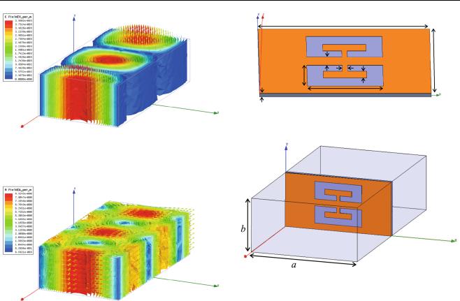
Fig. 3 Magnitude and vector of electric field in rectangular waveguide
Fig. 4 Magnitude and vector of magnetic field in rectangular waveguide
a waveguide. From practical point of view, many systems use a dominant TE10 mode operation for rectangular waveguide. For TE10 mode operation, the electric field components are given as [1].
Exþ ¼ 0; |
|
|
|
|
|
|
ð10Þ |
|
A10 p |
p |
|
||||
Eyþ ¼ |
|
|
|
sin |
|
x e jbzz; |
ð11Þ |
|
a |
a |
|||||
Ezþ ¼ 0; |
|
|
|
|
|
|
ð12Þ |
Simulated results of electric field magnitude and direction for TE10 mode operation are shown in Fig. 3. Magnetic field components for TE10 are given as [1].
|
|
b |
|
|
p |
p |
|
||||||
Hxþ ¼ A10 |
z |
|
|
|
sin |
|
x e jbzz; |
ð13Þ |
|||||
xl |
a |
a |
|||||||||||
Hyþ ¼ 0; |
|
|
|
|
|
|
|
|
|
|
ð14Þ |
||
|
A10 |
|
|
|
p 2 |
|
|
p |
|
||||
Hzþ ¼ j |
|
|
|
cos |
|
x e jbzz: |
ð15Þ |
||||||
xl |
a |
a |
|||||||||||
Figure 4 shows simulated results of magnetic field magnitude and direction for TE10 mode operation.
u |
|
d |
v |
s |
c |
w |
|
l |
|
h |
|
Fig. 5 Proposed waveguide filter |
|
Fig. 6 Filter configuration in rectangular waveguide
4 Overview of proposed filter
There are various methods to design waveguide filters. Generally planar waveguide filters are designed using coupling resonators. Proposed waveguide filter is designed using one unit cell of complementary symmetric split-ring resonator (CSSRR) which is negative image of symmetric split-ring resonator (SSRR). CSSRR has been etched on copper sheet of dimensions u = 15.79 mm, v = 7.89 mm and 30 lm thickness. RT/Duroid 5880 is used as substrate of thickness h = 0.5 mm and permittivity constant 2.2. The dimensions of CSSRR are much smaller than the wavelength of incident wave and given as w = 2.55 mm, l = 7 mm, s = 0.75 mm, c = 0.8 mm, d = 1 mm. Proposed filter is shown in Fig. 5. Proposed filter is placed across a rectangular waveguide (WR62) as shown in Fig. 6. The inner dimension of WR62 are a = 15.79 mm and b = 7.89 mm and it operates in Ku band.
5 Simulation results
Results are calculated numerically using HFSS simulations. Figure 7 shows the simulated results of the return loss S11 and insertion loss S21 for the proposed filter. The
123

T. ul Haq et al.
Fig. 7 Frequency behavior of filter
Fig. 9 Q factor versus design parameter s
Fig. 8 Simulated transmission coefficient spectra corresponding to different values of design parameter s
insertion loss is about 0.07 dB and return loss is 34 dB at the resonant frequency. The filter present wide passband properties which cover the frequencies from 11.6 to 13.6 GHz. Half power bandwidth of filter is 2 GHz and Q factor is 6.35. Moreover, it is noticed that changing the design parameter s of the resonator the resonant frequency and half power bandwidth can be altered. The simulated results of insertion loss S21 for different values of design parameter s is shown in Fig. 8. For design parameter s = 0.5 mm the insertion loss is about 0.11 dB and return loss is 33.5 dB with resonant frequency 12.1 GHz. The filter provides the passband properties between the frequency range of 11.2–12.8 GHz. For design parameter s = 1.0 mm the insertion loss is about 0.05 dB and return loss is 34.6 dB with resonant frequency 13.37 GHz. The filter provides the passband properties between the frequency range of 12–14.5 GHz. The effect of design parameter s on Q factor is shown in Fig. 9. It can be observed that high value of Q provides a narrow passband and low value of Q gives a wide passband.
6 Conclusion
In this paper, complementary symmetric split-ring resonator (CSSRR) has been used to design bandpass filter for rectangular waveguide. By optimization of geometrical parameters, a passband of 2 GHz (11.6–13.6 GHz) is achieved. CSSRR structure is very easy to tune. It is demonstrated that by changing design parameters, the resonant frequency and quality factor can be improved. Proposed filter can be used in satellite communication and radar applications.
Acknowledgments The authors would like to acknowledge Faculty of Electronic Engineering, Ghulam Ishaq Khan Institute of Engineering Sciences and Technology (GIKI), for supporting this work. The authors are also thankful to Dr. Adnan Noor (Assistant Professor GIKI) for technical help in HFSS 14.0.
References
1.C.A. Balanis, Advanced Engineering Electromagnetics (John Wiley and Sons. Inc, New York, 2012)
2.D.M. Pozar, Microwave Engineering (Wiley, Hoboken, 2012)
3.D. Oloumi et al., Size reduction and bandwidth enhancement of a waveguide bandpass filter using fractal-shaped irises. IEEE Antennas Wirel. Propag. Lett. 8, 1214–1217 (2009)
4.D. Budimir et al., Waveguide filters using T-shaped resonators. Electron. Lett. 47, 38–40 (2011)
5.M. Khalaj Amirhosseini, Microwave filters using waveguides filled by multi-layer dielectric. Prog. Electromagn. Res. 66, 105–110 (2006)
6.X.Q. Lin et al., Metamaterial-inspired waveguide filters with compact size and sharp skirt selectivity. J. Electromagn. Waves Appl. 27(2), 224–232 (2013)
7.J.B. Pendry, A.J. Holden, D.J. Robbins, Magnetism from conductors and enhanced nonlinear phenomena. IEEE Trans. Microw. Theory Tech. 47(11), 2075–2084 (1999)
8.R. Marqus et al., Left-handed-media simulation and transmission of EM waves in subwavelength split-ring-resonator-loaded
123

Design and implementation of waveguide bandpass filter using complementary metaresonator
metallic waveguides. Phys. Rev. Lett. 89(18), 183901–183905 (2002)
9.S. Hrabar, J. Bartolic, Z. Sipus, Waveguide miniaturization using uniaxial negative permeability metamaterial. IEEE Trans. Antennas Propag. 53(1), 110–119 (2005)
10.N. Ortiz et al., Complementary split-ring resonator for compact waveguide filter design. Microw. Opt. Technol. Lett. 46(1), 88–92 (2005)
11.F. Falcone, T. Lopetegi, J.D. Baena, M. Sorolla, Effective negativestropband microstrip lines based on complementary split ring resonators. IEEE Microw. Wirel. Compon. Lett. 14(6), 280–282 (2004)
12.H. Bahrami et al., Using complementary split ring resonators (CSRR) to design bandpass waveguide filters. in Proceedings of Asia-Pacific Microwave Conference, pp. 749–753 (2007)
13.N. Suntheralingam, D. Budimir, Compact waveguide bandpass filters with enhanced stopband performance. in Proceedings of Asia-Pacific Microwave Conference, pp. 1–4 (2008)
14.S. Fallahzadeh et al., A novel dual-band stopband waveguide filter using split ring resonator. Prog. Electromagn. Res. Lett. 12, 133–139 (2009)
15.R. Rezaiesarlak et al., A dual behavior resonator structure for designing multi-band bandpass waveguide filters. in Proceedings of Asia-Pacific Microwave Conference, pp. 1110–1113 (2010)
16.O. Glubokov, D. Budimir, Compact E-plane doublet structures for modular filter design. in Proceedings of European Microwave Conference, pp. 1253–1256 (2010)
17.Y. Liu, H. Ma, A broadband bandpass rectangular waveguide filter based on metamaterials. in International Workshop on Metamaterials (Meta), pp. 1–4 (2012)
18.S. Stefanovski, M. Potrebic, D. Tosic, Design and analysis of bandpass waveguide filters using novel complementary split ring resonators. in 11th International Conference on Telecommunications in Modern Satellite, Cable and Broadcasting Services (TELSIKS), pp. 257–260 (2013)
19.L. Yechou, A. Tribak, M. Kacim, J. Zbitou, A. Mediavilla, Kuband waveguide band-pass filter with iris radius. in International Conference on Multimedia Computing and Systems (ICMCS), pp. 1435–1438 (2014)
20.Y. Cai, L. Yang, Y. Zhang, W. Cao, Z. Qian, HMSIW bandstop filter loaded with half complementary split-ring resonator. Electron. Lett. 51(8), 632–633 (2015)
123