

диафрагмированные волноводные фильтры / 65170e1a-1816-4fb8-8207-2fe5a4041fff
.pdfThis article was downloaded by: [University of Nebraska, Lincoln] On: 29 October 2013, At: 01:28
Publisher: Taylor & Francis
Informa Ltd Registered in England and Wales Registered Number: 1072954 Registered office: Mortimer House, 37-41 Mortimer Street, London W1T 3JH, UK
Electromagnetics
Publication details, including instructions for authors and subscription information: http://www.tandfonline.com/loi/uemg20
Controllable Dual-Band E-Plane Waveguide T-Junction Using Extended S- Shaped Ring Resonators
Jafar Khalilpour a
a Faculty of Electrical Engineering , Aeronautical University of Science and Technology , Tehran, Iran
Published online: 02 Aug 2011.
To cite this article: Jafar Khalilpour (2011) Controllable Dual-Band E-Plane Waveguide T- Junction Using Extended S-Shaped Ring Resonators, Electromagnetics, 31:6, 460-468, DOI: 10.1080/02726343.2011.590965
To link to this article: http://dx.doi.org/10.1080/02726343.2011.590965
PLEASE SCROLL DOWN FOR ARTICLE
Taylor & Francis makes every effort to ensure the accuracy of all the information (the “Content”) contained in the publications on our platform. However, Taylor & Francis, our agents, and our licensors make no representations or warranties whatsoever as to the accuracy, completeness, or suitability for any purpose of the Content. Any opinions and views expressed in this publication are the opinions and views of the authors, and are not the views of or endorsed by Taylor & Francis. The accuracy of the Content should not be relied upon and should be independently verified with primary sources of information. Taylor and Francis shall not be liable for any losses, actions, claims, proceedings, demands, costs, expenses, damages, and other liabilities whatsoever or
howsoever caused arising directly or indirectly in connection with, in relation to or arising out of the use of the Content.
This article may be used for research, teaching, and private study purposes. Any substantial or systematic reproduction, redistribution, reselling, loan, sub-licensing, systematic supply, or distribution in any form to anyone is expressly forbidden. Terms & Conditions of access and use can be found at http://www.tandfonline.com/page/terms- and-conditions

Downloaded by [University of Nebraska, Lincoln] at 01:28 29 October 2013
Electromagnetics, 31:460–468, 2011
Copyright © Taylor & Francis Group, LLC
ISSN: 0272-6343 print/1532-527X online
DOI: 10.1080/02726343.2011.590965
Controllable Dual-Band E -Plane Waveguide
T-Junction Using Extended S-Shaped
Ring Resonators
JAFAR KHALILPOUR 1
1Faculty of Electrical Engineering, Aeronautical University of Science and Technology, Tehran, Iran
Abstract In this novel application, an X-band E-plane waveguide T-junction with an inductive septum is modified in the form of a dual-band power divider using a slab of S-shaped ring resonators in each arm of the junction. Results obtained from measurement and numerical simulations of a specific structure are presented. The results show that the structure can be used in a wide frequency band below cut-off frequency of the hollow waveguide T-junction with low insertion loss. Also, by using finite element simulation, it is shown that the frequency range of each of the two bands of operation can be adjusted by changing the slab substrate properties, permittivity, thickness, and its position inside each waveguide.
Keywords metamaterial, T-junction, dual-band
1. Introduction
Because of lower loss and high power handling capability, metallic waveguides and their components are widely used in microwave, radar, and antenna technology. It is known from electromagnetics that for the propagation of waves through a waveguide, the width of the waveguide cross-section must be at least one-half of the wavelength (Balanis, 1989). Thus, waveguide components are excessively large at low frequencies. Also, in many applications, multi-band waveguide components are needed.
Metamaterials, where either their permittivity and permeability (or both) must be negative (Veselago, 1968; Pendry et al., 1996, 1999; Shelby et al., 2001), can be used for the miniaturization of waveguides and modifying the frequency response of waveguide components. In recent studies, a rectangular metallic waveguide periodically loaded with splitring resonators (SRRs) was proposed by many research groups (Marques et al., 2002a; Hrabar et al., 2005; Hrabar & Jankovic, 2006; Baena et al., 2005a, 2005b). SRRs are the resonant inclusions that were proposed in several shapes (Marques et al., 2002b; Simovski & He, 2003; Chen et al., 2004; Ekmekci & Turhan-Sayan, 2009; Wang et al., 2009) and are usually used for construction of metamaterial with negative permeability. Transmission and radiation characteristics of such a waveguide have been investigated (Hrabar et al., 2005; Hrabar & Jankovic, 2006). It is shown that because such a waveguide supports propagation of the backward wave below the cut-off frequency, the transversal dimension of the waveguide can be miniaturized (Hrabar et al., 2005). Because SRRs are resonance
Received 27 October 2010; accepted 4 May 2011.
Address correspondence to Jafar Khalilpour, Faculty of Electrical Engineering, Aeronautical University of Science and Technology, Tehran, Iran. E-mail: j_khalilpour@yahoo.com
460
Downloaded by [University of Nebraska, Lincoln] at 01:28 29 October 2013
Controllable Waveguide T-Junction |
461 |
structures, the width of transmission below cut-off is very narrow. In Baena et al. (2005a, 2005b), a rectangular waveguide loaded with SRRs with a resonance frequency further than that of the hollow waveguide cut-off frequency was analyzed. A stopband appears at the frequency band of the negative transversal permeability of the SRRs.
S-shaped ring resonators, which have low insertion loss and a wide bandwidth of backward wave propagation, were proposed as double negative elements (Chen et al., 2004, 2005). These elements are used for the construction of multi-frequency resonators (Wang et al., 2006). They are used in the form of anisotropic uniaxial metamaterial with transversal negative effective permeability for wave propagation below the cutoff frequency of a hollow rectangular waveguide (Khalilpour & Hakkak, 2009). Also, in Khalilpour and Hakkak (2010), a slab of S-shaped ring resonators is used to fill a rectangular waveguide for the construction of a band-rejection waveguide filter with adjustable bandwidth and cut-off frequency.
A waveguide T-junction is a three-port device that is used to split an input signal from port 1 into two outgoing signals from ports 2 and 3. In this component, a septum is used for minimizing wave reflection. This article studies the effect of using a slab of S-shaped ring resonators in each arm of an X-band E -plane waveguide T-junction. It is shown that the structure can be used as a dual-band waveguide power divider. Because the frequency response of the structure is dependent on resonance frequency and the frequency band of negative in the metamaterial, it is possible to adjust the power divider characteristics by tuning the effective properties of metamaterials. The frequency range of each of the two operation bands can be adjusted by changing the slab substrate properties—permittivity, thickness, and position of slabs inside each waveguide (Shen & Varadan, 2007).
2. Analysis of Structure
In this part, an X-band E -plane waveguide T-junction, where each of its arms consist of a 56-mm-long metamaterial-loaded X-band WR90 rectangular waveguide (22.86 mm 10.16 mm), is investigated. This structure is shown in Figure 1. A slab that consists of extended S-shaped elements with resonance frequency at 8.8 GHz (Khalilpour & Hakkak, 2010) is placed along the axial plane of each waveguide. Each arm of the T-junction is terminated to a C-band coaxial to waveguide transition.
Each metamaterial slab contains 15 extended S-shaped elements that are printed on both sides of the 0.508-mm-thick Rogers RT Duroid 5880, with relative permittivity 2.2 in the opposite direction and a lattice constant of 4 mm. The unit cell dimensions are the same dimensions as reported in Khalilpour and Hakkak (2010). The photo of the fabricated slab and the unit cell dimensions are shown in Figure 2.
Two S units are connected to each other for construction of an extended S-shaped ring resonator. The equivalent circuit for each S unit is shown in Figure 3 (Chen et al., 2004).
Resonance and magnetic plasma frequencies of the elements are obtained, respec-
tively, from Eqs. (1) and (2) (Chen et al., 2005): |
|
|
|
|
|
|
|
||||||||||||
!m0 D s |
|
|
|
|
|
|
|
|
|
|
|
|
|
|
|
|
|
|
(1) |
|
0 FS |
C |
C C1 |
; |
|
|
|
|
|
|
|
|
|||||||
1 |
|
l |
|
2l |
|
|
|
|
|
|
|
|
|
|
|
|
|||
!mp D s |
|
|
|
|
|
|
|
|
|
|
|
|
|
||||||
0 FS |
.1 2F / C |
C C1 |
|
D !m0 s |
|
.1 2F / ; |
(2) |
||||||||||||
|
|
|
1 |
|
|
|
|
|
l |
|
2l |
|
|
|
1 |
|
|
|
|

462 |
J. Khalilpour |
Downloaded by [University of Nebraska, Lincoln] at 01:28 29 October 2013
Figure 1. Metamaterial-filled E -plane waveguide T-junction. (color figure available online)
Figure 2. (a) Unit cell dimensions and (b) photo of metamaterial slab. (color figure available online)
Figure 3. Equivalent circuit for each S unit.

Controllable Waveguide T-Junction |
463 |
Downloaded by [University of Nebraska, Lincoln] at 01:28 29 October 2013
Figure 4. Magnitude of S parameters of waveguide power divider. (color figure available online)
where !mp is the magnetic plasma frequency, !m0 is the magnetic resonance frequency, l is the equivalent inductance, C and C1 are the equivalent capacitances in Figure 3, and F is the filling factor of the unit cell (the fractional volume of the cell occupied by the loops of S-shaped elements).
The structure of Figure 1 was simulated by using Ansoft HFSS-11 (Ansoft, USA) (based on the finite element method). The amplitude of the wave transmission coefficient from port 1 to port 2 (S12) and port 3 (S13) are shown in Figure 4. This figure also shows the reflection coefficient from port 1 (S11). It is evident that the structure can be used as a dual-band waveguide power divider. It can be seen that the S12 and S13 curves are completely similar to each other, and S11 is equal to one in the stopband. It is clearly observed that power division in the X-band waveguide T-junction occurs below the cutoff frequency of its dominant mode TE10 (6.56 GHz), i.e., from 4.3 GHz to 6.56 GHz, due to the effective dielectric permittivity of the metamaterial. Also, a stopband exists between about 8.5 and 13.9 GHz due to the frequency band of the negative transversalof the metamaterial (Khalilpour & Hakkak, 2009), and total reflection occurs in this frequency band. The second passband begins from 13.9 GHz.
3. Experimental Verification
In order to verify the simulation result, three slabs of S-shaped metamaterial samples were fabricated and put into the T-junction arms. The test set-up consists of two C-band coaxial-to-rectangular waveguide adaptors, a C-band waveguide match load, and an X- band E -plane waveguide T-junction that was loaded with metamaterial. Figure 5 shows the set-up for the experiment.
The transmission coefficients of wave transmission from port 1 to ports 2 (S12) and 3 (S13) were recorded in the frequency range from 4–15 GHz using an HP8722D network analyzer (Hewlett-Packard, USA). The measured transmission coefficients of the structure are shown in Figure 6. It can be seen that the measured and simulated results are in good harmony, although experimental results show narrower stopband and more

464 |
J. Khalilpour |
Downloaded by [University of Nebraska, Lincoln] at 01:28 29 October 2013
Figure 5. Photo of experimental set-up. (color figure available online)
insertion loss than the simulation results. Also, ripples in the passbands of the structure in the experimental results are due to the dispersive property of the metamaterial.
4. Tuning of the Structure
Because the frequency range of the two passbands and the stopband of structure is determined by the resonance frequency and the frequency band of negative in the metamaterial, it is possible to control the power divider characteristics by tuning the effective properties of the metamaterial. The effects of varying the slabs substrate dielectric permittivity, thickness, and position inside the waveguide were studied.
Figure 6. Magnitude of measured and simulated S12 and S13 parameters of waveguide power divider. (color figure available online)
Downloaded by [University of Nebraska, Lincoln] at 01:28 29 October 2013
Controllable Waveguide T-Junction |
465 |
4.1.Changing Substrate Permittivity
It is expected that with increasing the permittivity of the substrates of metamaterial, the effective permittivity of waveguide increases, and the width of the passband below the cutoff frequency of dominant mode (TE10) is increased. Also, with increasing permittivity of the substrates, the equivalent capacitance of the equivalent circuit model is increased and, according to Eq. (1), the resonance frequency of metamaterial decreases and causes the upper cut-off frequency of the first passband to forcibly decrease.
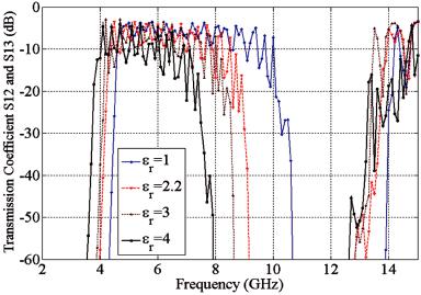
The frequency response of the power divider obtained by varying the real part of the relative permittivity of all slabs substrate from 1 to 4 while keeping its physical thickness fixed (0.508 mm) is shown in Figure 7. It can be seen that by varying the permittivity of the substrates from 1 to 4, the range of the two passbands is shifted to lower values. The width of passband below the cut-off frequency of the dominant mode (TE10 ) increases with an increase in the slab substrate relative permittivity. In other words, in the first passband propagation, the beginning frequency of the structure drops from 4.6 GHz for "r D 1 to 3.9 GHz for "r D 4.
Also, the cut-off frequency of the stopband between the two passbands at 10.1 GHz for "r D 1 shifts to a lower value of 7.4 GHz for "4. Although ripples are increased in the second passband, both depth of the cut-off and stopband, the bandwidth increases with increasing the slab substrate relative permittivity. The beginning frequency of the second passband also decreases with increasing substrate permittivity.
4.2.Varying Substrate Physical Thickness
Increasing the physical thickness substrate of slabs will increase the filling factor of the metamaterial, and according to Eq. (1), the resonant frequency of elements will be decreased. Thus, the upper cut-off frequency of the first passband is forced to go down. Increasing the physical thickness substrate of slabs will also increase the effective
Figure 7. Magnitude of S12 and S13 parameters of waveguide power divider for varying the permittivity of slab substrate. (color figure available online)

466 |
J. Khalilpour |
Downloaded by [University of Nebraska, Lincoln] at 01:28 29 October 2013
Figure 8. Magnitude of S12 and S13 parameters of waveguide power divider for various thicknesses of the slab substrate. (color figure available online)
permittivity of the waveguide and the width of the passband below the cut-off frequency of the dominant mode (TE10 ).
The behavior of the structure when varying the physical thickness substrate of slabs from 0.508 mm to 2.032 mm while keeping its permittivity fixed ("r D 2:2) is shown in Figure 8. This figure shows the amplitude of transmission coefficients S12 and S13 of the power divider for 0.508-, 1.016-, and 2.032-mm physical thickness of the slab substrate.
A comparison of Figures 7 and 8 indicates that the effect of increasing slab thickness on structure properties is quite similar to the effect of increasing the slab substrate relative permittivity. It can be seen from Figure 8 that when the physical thickness of the substrate is varied from 0.508 to 2.032 mm, the frequency range of the first passband power divider decreases from 4.3–8.9 GHz to 3.4–6.3 GHz.
4.3.Positioning the Slab Inside the Waveguide
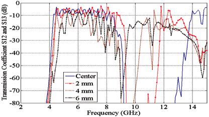
The stop bandwidth of this filter can be very wide or very narrow. The bandwidth of the stopband can be adjusted by changing the distance of the slab from the central line of the waveguide.
The width of the stopband between the two passbands of the structure can be controlled by adjusting the distance of the slabs from the central plane of the waveguides. In other words, the two passbands of the power divider can be very close or far away from each other by varying the position of metamaterial slabs inside the waveguides. Results that are obtained by varying the distance of the slabs from the central line of the waveguides are shown in Figure 9. This figure shows the amplitude of transmission coefficients S12 and S13 of the structure for 2-, 4-, and 6-mm distances between the slab and central plane of the waveguide. Figure 9 clearly shows that the bandwidth of the stopband can be adjusted by changing the distance of the slab from the central line of the waveguide. The stopband bandwidth drops from about 5.4 GHz to about 900 MHz by increasing the distance from the central plane to 6 mm. This is expected, because the amplitude of the electric field at the central plane of the waveguides is maximum, and
Controllable Waveguide T-Junction |
467 |
Downloaded by [University of Nebraska, Lincoln] at 01:28 29 October 2013
Figure 9. Magnitude of S12 and S13 parameters of waveguide power divider for different distances of slabs from central line of waveguides. (color figure available online)
the effect of metamatrial slabs in the behavior of waveguides is decreased when their distances from the central plane of the waveguides are increased.
5. Conclusion
In this article, each arm of an E -plane waveguide T-junction with an inductive septum was loaded with a slab of S-shaped ring resonators. Results show that this structure can be used as a dual-band power divider with an adjustable frequency range of two passbands and width of rejection band between them. This article focused on the effects of slabs substrate properties (permittivity and thickness) and their position inside the waveguides on the structure response. Results show that the frequency range of the two passbands is very sensitive to a change of substrate permittivity and thickness; also, the width of the stopband can be controlled by adjusting the position of metamaterial slabs inside the waveguides.
References
Baena, J. D., L. Jelinek, & R. Marques. 2005a. Reducing losses and dispersion in multilayer metamaterial tunneling devices. New J. Phys. 7:166.
Baena, J. D., L. Jelinek, R. Marques, & F. Medina. 2005b. Near-perfect tunneling and amplification of evanescent electromagnetic waves in a waveguide filled by a metamaterial: Theory and experiments. Phys. Rev. B 72:075116.
Balanis, C. A. 1989. Advanced engineering electromagnetics, chap. 8. New York: Wiley.
Chen, H., L. Ran, J. Hungfu, X. Zang, K. Chen, T. M. Grzegorczyk, & J. A. Kong. 2004. Lefthanded materials composed of only S-shaped resonators. Phys. Rev. E 70:057605.
Chen, H. S., L. X. Ran, J. T. Hungfu, X. M. Zang, & K. S. Chen. 2005. Magnetic properties of S-shaped split-ring resonators. Progr. Electromagn. Res. 51:231–247.
Ekmekci, E., & G. Turhan-Sayan. 2009. Comparative investigation of resonance characteristics and electrical size of the double-sided SRR, BC-SRR and conventional SRR type metamaterials for varying substrate parameters. Progr. Electromagn. Res. B 12:35–62.
Downloaded by [University of Nebraska, Lincoln] at 01:28 29 October 2013
468 J. Khalilpour
Hrabar, S., J. Bartolic, & Z. Sipus. 2005. Waveguide miniaturization using uniaxial negative permeability metamaterial. IEEE Trans. Antennas Propagat. 53:110–119.
Hrabar, S., & G. Jankovic. 2006. Basic radiation properties of waveguides filled with uniaxial single-negative metamaterials. Microw. Optical Technol. Lett. 48:2587–2591.
Khalilpour, J., & M. Hakkak. 2009. S-shaped ring resonator as anisotropic uniaxial metamaterial used in waveguide tunneling. J. Electromagn. Waves Appl. 23:1763–1772.
Khalilpour, J., & M. Hakkak. 2010. Controllable waveguide bandstop filter using S-shaped ring resonators. J. Electromagn. Waves Appl. 24:587–596.
Marques, R., J. Martel, F. Mesa, & F. Medina. 2002a. Left-handed-media simulation and transmission of EM waves in subwavelength split-ring-resonator-loaded metallic waveguides. Phys. Rev. Lett. 89:139011–139014.
Marques, R., F. Medina, & R. Rafii-El-Idrissi. 2002b. Role of anisotropy in negative permeability and left-handed metamaterials. Phys. Rev. B 65:1–6.
Pendry, J. B., A. Holden, W. Stewart, & I. Youngs. 1996. Extremely low frequency plasmons in metallic macrostructures. Phys. Rev. Lett. 76:4773–4776.
Pendry, J. B., A. J. Holden, D. J. Robbins, and W. J. Stewart. 1999. Magnetism from conductors and enhanced nonlinear phenomena. IEEE Trans. Microw. Theory Techniq. 47:2075–2084.
Shelby, R. A., D. R. Smith, & S. Schultz. 2001. Experimental verification of a negative index of refraction. Science 292:77.
Shen, Z. & V. V. Varadan. 2007. Tuning the effective properties of metamaterials by changing the substrate properties. J. Appl. Phys. 101:014909(1)–(7).
Simovski, C. R., & S. He. 2003. Frequency range and explicit expressions for negative permittivity and permeability for an isotropic medium formed by a lattice of perfectly conducting • particles based on the quasi-static Lorentz theory. Phys. Lett. A 311:254–263.
Veselago, V. G. 1968. The electrodynamics of substances with simultaneously negative value of " and . Sov. Phys. Usp. 10:509–514.
Wang, D., L. Ran, B.-I. Wu, H. Chen, J. Hungfu, T. M. Grzegorczyk, & J. A. Kong. 2006. Multiple-frequency resonator based on dual-band s-shaped left-handed material. Optics Express 14:12288-12294.
Wang, J., S. Qu, J. Zhang, H. Ma, Y. Yang, C. Gu, & X. Wu. 2009. A tunable left-handed metamaterial based on modified broadside-coupled split-ring resonators. Progr. Electromagn. Res. Lett. 6:35–45.