

диафрагмированные волноводные фильтры / 71b7c8a4-c9a6-49d8-89c2-62ebde31201e
.pdfReceived March 23, 2019, accepted April 17, 2019, date of publication April 22, 2019, date of current version May 1, 2019.
Digital Object Identifier 10.1109/ACCESS.2019.2912496
Slow-Wave Groove Gap Waveguide
Bandpass Filter
ZHIQIANG LIU 1, (Student Member, IEEE), JING-YA DENG
 2, (Member, IEEE), AND
DONGQUAN SUN 2, (Member, IEEE)
1State Key Laboratory of Millimeter Waves, Southeast University, Nanjing 210096, China
2School of Physics and Optoelectronic Engineering, Xidian University, Xi'an 710071, China
Corresponding authors: Jing-Ya Deng (jydeng@xidian.edu.cn) and Dongquan Sun (dqsun87@163.com )
This work was supported in part by the Sustainedly Supported Foundation by the National Key Laboratory of Science and Technology on Space Microwave under Grant 2018SSFNKLSMT-08, and in part by the Fundamental Research Funds for the Central Universities under Grant JB180506.
 ABSTRACT Gap waveguide (GW) is a promising technology for its advantages of self-package and easy assembly without the requirement of contact. In this paper, a miniaturized groove GW (GGW) called slow-wave GGW (SW-GGW) is presented for the rst time. The slow-wave feature is implemented by introducing symmetrical capacitive quasi-periodic corrugations inside the GGW. To obtain more design and manufacturing exibility, all the four walls of the SW-GGW are separated utilizing the gap waveguide technology. A six-order iris SW-GGW band-pass lter is designed, whose length is reduced to 57.1% of the conventional iris rectangular waveguide lter with the same response. The irises of the SW-GGW lter are located on the broad-side walls in half-height form. This con guration not only reduces the manufacturing complexity but also makes it possible to implement lter with different responses by simply replacing the broad-side walls. The measured fractional bandwidth (FBW) of the SWGGW lter is around 3.88% at 11.87 GHz with the return loss better than 18 dB and minimum insertion loss of 0.5 dB.
 INDEX TERMS Gap waveguide, band pass lter, iris waveguide lter, slow wave.
I. INTRODUCTION
Gap waveguide (GW) technology has received much attention recently due to its non-contact characteristic. Compared to its rectangular waveguide (RW) counterparts, GW circuits eliminate the strict requirement of good surface contact between the sub-components while assembling [1]. The non-contact characteristic is achieved by placing a perfect electric conductor (PEC) plate and a perfect magnetic conductor (PMC) plate in parallel with a permitted air gap to construct an electromagnetic band-gap (EBG) structure. The cutoff wavelength is four times of the distance of the two plates. The PMC plate is commonly realized by an arti cial magnetic conductor (AMC) plate with periodic elements, such as periodic metal pins, so-called bed of nails, or mushroom-type conductive elements. Taking advantage of the non-contact characteristic, GW technology has been widely applied to design various microwave and millimeter wave circuits, such as PMC packaging of planar circuits [2] [4], GW antennas [5] [7], couplers [8], [9],
The associate editor coordinating the review of this manuscript and approving it for publication was Yingsong Li.
contactless waveguide anges [10], con gurable or bendable GWs [11], and waveguide connectors with low passive-intermodulation [12].
Groove GW (GGW) band-pass lters (BPF) using high-Q GW cavity resonators is a research hotspot and have been extensively investigated [13] [20]. The biggest difference among the reported lters is the coupling mechanism. The coupling coef cients of adjacent resonators are commonly controlled by tuning the heights of the intermediate pins [14] [16], and the displacement of the resonators [17], [18]. The transmission and re ection performances of the GGW BPF are very close to their RWG counterparts. The metal pins in these lters are generally as high as the narrow wall of the GGW, posing a dif culty for low-cost manufacturing. As an alternative of conventional iris RWG BPF, an iris GGW BPF was presented in [19]. In [20], a novel GGW called full-GGW, consisting of four individual plates, two AMC plates and two PEC plates, was presented and applied to design a capacitive iris BPF. The irises of the full-GGW BPF are arranged along its broad-side walls. The widths of the irises are narrower than the width of the wide wall for better manufacturing exibility. The narrowed irises results in
2169-3536 2019 IEEE. Translations and content mining are permitted for academic research only.
VOLUME 7, 2019 Personal use is also permitted, but republication/redistribution requires IEEE permission. 52581 See http://www.ieee.org/publications_standards/publications/rights/index.html for more information.

Z. Liu et al.: SW-GGW Bandpass Filter
a reduction of isolation of adjacent cavity resonators. So it is not suitable for designing narrow band BPF. Another problem facing all the above lters is that manufacturing the large amount of pins is quite time consuming, making it not suitable for mass production. Therefore, it is necessary to develop some measures to reduce the dimension of the GGW.
Slow wave waveguide with periodic corrugations/ridges loading inside is widely used in substrate integrated waveguide circuits [21], traveling-wave tube devices [22] and horn antennas [23]. In this paper, slow-wave GGW (SW-GGW) with symmetrical E-plane quasi-periodic corrugations is introduced to GW circuits for the rst time. The dispersion performance of the SW-GGW is investigated and an iris SW-GGW BPF centered at 11.9GHz is designed. The irises are divided into two halves for the convenience of processing. A prototype of the iris SW-GGW BPF is manufactured and tested. The measured insertion loss (IL) of iris SW-GGW BPF is better than 0.8dB with its return loss (RL) greater than 18dB. The longitudinal dimension of the proposed BPF is reduced to be 57.1% of the classical irislter.
This paper is organized as follows. In section II, the design of the contactless EBG structure and the GGW are presented, respectively. In section III, the dispersion performance of the SW-GGW is carefully investigated. In section IV, the design procedure of the iris SW-GGW BPF is presented. Finally, in section V, a short conclusion and discussion is presented.
II. SLOW-WAVE GAP WAVEGUIDE
A. GEOMETRY OF THE PROPOSED GGW
The geometry of the proposed GGW is shown is Fig.1. The GGW is composed of four separate metal plates, which includes two smooth plates and two plates with AMC surfaces on its both sides. The AMC surface is in the form of bed of nails.
The port width and height of the gap waveguide are a and b, respectively. In this work, the port dimension of the gap waveguide is chosen to be the same as WR75 RWG, which is 19.05mm 9.525mm. The dimension of the metal pins is w w hp. The distance of the air gap of two adjacent pins is g, and the height of air gap between pins and E-plane walls is ha. The air gap is achieved by four convex square metal pins with height of ha along the edges of the smooth metal plates as shown in Fig. 1(b). The smooth metal plates and the AMC metal plates are assembled together to form the complete GGW. To avoid misalignment while assembling, two dowel pins are used.
B. DESIGN OF THE EBG STRUCTURE AND THE GGW
The design target here is a GGW with the same inner dimensions of WR75 waveguide. The rst step is to determine the dimensions of the contactless EBG structure. There are some guidelines for the design procedure. The height of the bed of nails should be quarter of the wavelength of the center frequency of the stopband. The center frequency of
52582
FIGURE 1. Geometry of gap waveguide. (a) Input or output port view.
(b) Internal view with the top and right walls removed.
WR75 waveguide is about 12.5GHz and its wavelength is 24mm in free space. The height of the bed of nails should be 6mm. Considering that the two AMC surfaces are arranged back to back on the narrow wall, the total height of the bed of nails is 12mm, which is about 2.5mm thicker than the width of the narrow wall (9.525mm). So, the height of the bed of nails should be reduced. There is a tradeoff between the height of the pins and the width and period of the pins. If the width or the period of the pins is increased, the stopband of the EBG structure will move toward the
lower frequency band. The diagonal length of adjacent pins, p
2 g, should be smaller than half wavelength of the operation frequencies [20]. Otherwise, vertically polarized electromagnetic wave will be excited between the gaps of the pins. In this work, g should be smaller than 7.1 mm for the operating frequency band of WR75 RWG. A smaller value g D 4:1mm is selected here to leave suf cient stopband margin above 15GHz. The width of the metal pins is selected as w D 5:2mm. Considering that the periodic pins are located on both sides of the narrow-side walls, the metal pins should not be made too long in order to maintain good structural strength and to reduce the manufacturing dif culty. The height of the bed of nails is set to 2.5mm. A unit cell of the contactless EBG structure is shown in Fig. 2. Millimeter-wave simulation software CST studio is used to calculate the dispersion performance of the EBG structure. Simulated dispersion diagrams of the unit cell are depicted in Fig.3, where the lowest three modes are included. There is a stopband between mode 1 and mode 2, which ranges from 7.7GHz to 22.5GHz covering the entire WR75 waveguide frequency band.
VOLUME 7, 2019

Z. Liu et al.: SW-GGW Bandpass Filter
FIGURE 2. Unit cell of the parallel PEC-AMC surfaces.
(a) Three-dimension view. (b) Front view.
FIGURE 6. Geometry of the SW-GGW with its top broad-side wall removed.
FIGURE 7. Geometry of the unit cell of the SW-RW.
FIGURE 3. Dispersion diagrams of the unit cell of AMC-PEC surfaces. The dimensions are as follows: w D 5:2mm, g D 4:1mm, hp D 2:5mm.
ha D 0:2mm.
FIGURE 4. Geometry of the unit cell of the GGW.
FIGURE 5. Dispersion diagrams of the unit cell of GGW. The dimensions are as follows (Fig. 1): a D 19:05mm, b D 9:525mm, w D 5:2mm,
g D 4:1mm, hp D 2:5mm, and ha D 0:2mm.
Then, the transmission performance of the GGW is calculated using the unit cell of the GGW shown in Fig. 4. Fig. 5 shows the simulated dispertion diagrams of the GGW
including the lowest 7 modes. Mode 1, 2, 3, 4 and 5 are the modes supported by the EBG structures, while mode 6 and 7 are modes inside the GGW. For comparison, the dispersion curve of the TE10 mode of WR75 waveguide is also illustrated in Fig. 5. The dispersion curve of mode 6 is almost the same as the TE10 mode of WR75 waveguide. It indicates that the transmission mode of the GGW is very close to its RW counterpart.
C. DESIGN OF THE SW-GGW
It is well known that transmission lines with period loadings will divide its transmission frequency bands into passband and stopband alternatively [24], [25]. Because of the inductive or capacitive loadings, extra phase changes are added to the transmission line periodically. The passband of the transmission line will show quick-wave or slow-wave effect respectively.
In our work, capacitive metal corrugations are introduced on the broadside walls of the GGW to achieve the slowwave effect for the sake of size reduction. Fig. 6 shows the con guration of the SW-GGW with its top broadside wall removed. Two columns of transverse metal corrugations are symmetrically arranged on the top and bottom broadside walls of the GGW. The dimension of the transverse corrugations is wc tc hc and the loading period is dc. Because the dispersion performance of the GGW is very close to the RW, unit cell of the slow-wave rectangular waveguide (SW-RW), as shown in Fig. 7, is used to calculate the dispersion performance of the SW-GGW. Fig. 8 shows the simulated propagation constants of the SW-RW versus the
VOLUME 7, 2019 |
52583 |

Z. Liu et al.: SW-GGW Bandpass Filter
FIGURE 8. Simulated dispersion diagrams of the dominant mode of the unit cell of the SW-RW.
size of the corrugations and its loading period. It is obvious, the height of the corrugations, hc, is the major dimension that affects the propagation constant. With the increase of hc, the passband of the SW-RW moves towards lower frequencies, and the propagation constant at the same frequency increase rapidly.
III. DESIGN OF SW-GGW BPF
A. CONFIGURATION
On the basis of the proposed SW-GGW, a new iris BPF con-guration is presented, and its geometry is shown in Fig. 9. Excepting the corrugations, the SW-GGW is the same as the one in Fig. 6. Symmetrical irises pairs in half-height form are arranged on the top and bottom broad-side walls of the SW-GGW. An air gap leaves between the half-height irises to make the iris pairs do not need direct contact. The coupling factor can be tuned in a large range by simply changing the width of irises. This feature makes it suitable for the design of both wideband and narrowband lters. It is obvious that the longitudinal dimension of the BPF can be reduced significantly due to slow-wave effect of the SW-GGW. It should be noted that the corrugations and the irises are both located on
the broad-side walls. The response of the BPF can be changed by replacing the broad-side walls easily, while the narrowside walls can be reused.
The corrugations are loaded at the center of two adjacent irises. The dimensions of the half-height irises are wi t h(i D 1; 2; 3; 4). The thickness of the air gap between a pair of irises located on the top and bottom broad-side walls is gb. The distance between the irises pairs and narrow-side walls is ga. The dimensions of the corrugations are wc tc hi(i D 1; 2; 3). To introduce suf cient slow-wave effect, the height of the corrugations should be carefully determined. Firstly, the pass-band of the SW-GGW should cover the passband of the BPF. Secondly, the propagation constant should be as large as possible. Considering these two conditions, the thickness of the corrugations is xed to 2mm. The width of the corrugations is chosen to be 8.5mm to leave enough space between corrugations and irises for the convenience of milling processing. The air gaps ga and gb are xed to be 0.52mm and 0.40mm, respectively. The thickness of the irises is t D 2:5mm. The distance between two adjacent irises is chosen to be the same as the period of the corrugations, dc D 9:3mm.
52584 |
VOLUME 7, 2019 |

Z. Liu et al.: SW-GGW Bandpass Filter
FIGURE 9. Geometry of iris SW-GGW BPF. (a) Input or output port view.
(b) Internal view with the top and right walls removed.
FIGURE 10. Structure of two-coupled SW-RW resonators. (a) 3-D view.
(b)Top view. (c) Side view.
B.DESIGN PROCEDURE
Because the propagation constant of the SW-RW is very close to the SW-GGW with the same inner dimensions, SW-RW is used to replace the SW-GGW to accelerate the design process of the SW-GGW BPF. The design method of classical iris RWG BPFs is still useful for our design [26], [27]. In order to achieve the desired band-pass speci cations, three variables
FIGURE 11. (a) Resonant frequency versus wir with different hc .
(b) Coupling coefficient versus wir with different hc . The fixed dimensions are as follows: ga D 0:52mm, gb D 0:40mm, wc D 8:5mm, dc D 9:3mm, tc D 2:0mm, t D 2:5mm.
need to be calculated at rst. They are resonant frequency f0 of each resonator, coupling coef cient k between adjacent resonators and external quality factor Qex of the rst and last resonators.
The two SW-RW resonators in Fig. 10 are utilized to simulate the resonant frequency and coupling coef cient. The resonant frequency f0 and coupling coef cient k are calculated using the following equations [26]:
f0 D p |
f1 f2 |
|
(1) |
|||
|
|
|
|
|||
jkj D |
|
f12 f22 |
|
(2) |
||
f12 |
C f22 |
|||||
|
|
|
|
|
||
|
|
|
|
|
|
|
|
|
|
|
|
||
where f1 and f2 are the two eigenmodes of the resonators calculated using the eigenmode solver of ANSYS HFSS. The sign of the coupling coef cient k is not taken into account here because it is only meaningful for cross-coupled resonator lters.
The curves of resonant frequencies and coupling coef-cients with different widths of irises and heights of corrugations are plotted in Fig. 11. All the other parameters in the model remain unchanged. It shows that the desired resonant frequency and coupling coef cient can be obtained
VOLUME 7, 2019 |
52585 |
Z. Liu et al.: SW-GGW Bandpass Filter
FIGURE 12. Structure of first/last SWRW resonator. (a) 3-D view. (b) Top view. (c) Side view.
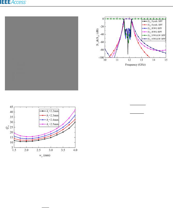
FIGURE 13. External quality factor Qex versus wir with different hc . The fixed dimensions are as follows: ga D 0:52mm, gb D 0:4mm,
wc D 8:5mm, dc D 9:3mm, tc D 2mm, t D 2:5mm.
by properly choosing the two dimensional parameters. This curve can be applied to determine the initial dimensions of the resonator by numerical interpolation.
The external quality factor Qex of the rst and last resonators is simulated using the structure in Fig. 12. It is calculated using [26]
Qex D |
!0 m |
(3) |
4 |
where !0 is the resonant frequency (rad/s) and m is the group delay of S11. It can be determined by locating the frequency of the maximum group delay of S11. Fig. 13 shows the relationship between external quality factor Qex and the coupling aperture size wir .
On the basis of the above simulated results, a six-order Chebyshev SW-GGW BPF with a pass-band ripple of 0.01dB is designed. The 3-dB fractional bandwidth (FBW) is chosen
52586
FIGURE 14. Calculated and simulated response of the six-order BPF.
to be 5.22% at the center frequency of 11.88GHz. The lowpass prototype element values are: g0 D g7 D 1, g1 D g6 D 0:8717, g2 D g5 D 1:6645, g3 D g4 D 1.9407. The coupling coef cient k and external quality factor Qex are calculated using the following equations [26]:
FBW
ki;iC1 D |
p |
|
(4) |
||
gi giC1 |
|||||
Q |
ex |
D |
gn gnC1 |
(5) |
|
|
|
FBW |
|
||
The calculated coupling coef cients are k12 D k56 D 0:0433, k23 D k45 D 0:0290, k34 D 0:0269. The external quality factor Qex D 16:7032.
The initial values of the key dimensional parameters of the SW-RW BPF are obtained according to coupling coef cient and external quality factor curves in Fig. 11 and Fig. 13. An overall optimization about the key dimensional parameters, including the heights hi of the corrugations and the width wi of the irises, is carried out using gradient method with the help of ANSYS HFSS. After the optimization, the narrowside walls of the BPF are replaced by the EBG structure and the SW-GGW BPF is obtained. The dimensional parameters are slightly tuned to achieve the optimum performances. The optimized dimensional parameters are as follows: h1 D 2:25mm, h2 D 2:94mm, h3 D 3:04mm, w1 D 2:06mm, w2 D 4:71mm, w3 D 5:20mm, w4 D 5:27mm. The total length of the SW-GGW BPF is 58.3mm. For comparison, a classical full-height iris RWG BPF with the same response is also designed using WR75 RWG. The length of the RWG BPF is 102.1 mm. Fig. 14 shows the frequency responses of the synthesized ideal six-order Chebyshev BPF, the SW-GGW BPF and the classical iris RWG BPF. The results agree well with each other. For simplicity, the conductor loss and surface roughness are not considered in the simulation process. It is worth mentioning that the length of the SWGGW BPF is reduced to 57.1% of the classical RWG BPF.
IV. FABRICATION AND MEASUREMENT
In order to validate the performances of the proposed SW-GGW BPF, a prototype of the SW-GGW BPF is manufactured successfully. The SW-GGW BPF is assembled
VOLUME 7, 2019

Z. Liu et al.: SW-GGW Bandpass Filter
FIGURE 15. Photograph of the proposed SW-GGW BPF. (a) Broad-side wall and narrow-side wall. (b) Port view of the assembled BPF. (c) Top view of the assembled BPF. (d) TRL calibration kit.
FIGURE 16. Measured and simulated S-parameters of the proposed SW-GGW BPF.
TABLE 1. Comparison with some reported GGW filters.
together and xed up using eight screws. Photographs of the manufactured prototype before and after assembling are illustrated in Fig. 15. A pair of SMA-to-WR75 RWG transitions is employed in the measurement. The effects of the transitions have been calibrated using a through-re ection-line (TRL) calibration kit..
The measured and simulated S-parameters of the proposed BPF prototype are both given in Figure 16 for comparison. The measured IL is better than 0.8 dB with RL better than
VOLUME 7, 2019
18 dB from 11.64 GHz to 12.1 GHz. The minimum IL is 0.5dB in the pass band. Good agreement has been achieved between the simulation and measurement, demonstrating the correctness of the design method. Performances of this work and some typical GGW BPFs in the literature are compared in Table 1.
V. CONCLUSION
SWGGW is proposed for the rst time and its dispersion performance has been carefully investigated. It shows advantages in minimizing the longitudinal dimension of GGW circuits and reducing their manufacturing time and cost. To validate its performance, a six-order iris SWGGW BPF, constructed by four separate walls, has been designed and manufactured. The corrugations and half-height irises are arranged on the broad-side walls of the lter to provide good manufacturing exibility. This arrangement also provides a practical way to fabricate lters with different responses by simply replacing the broad-side walls. The measured results of the SW-GGW BPF agree well with the simulated ones. Compared to the reported GGW BPFs, the length of the proposed SW-GGW BPF is signi cantly reduced.
REFERENCES
[1]P. S. Kildal, E. Alfonso, A. Valero-Nogueira, and E. Rajo-Iglesias, ``Local metamaterial-based waveguides in gaps between parallel metal plates,''
IEEE Antennas Wireless Propag. Lett., vol. 8, pp. 84 87, 2009.
[2]A. A. Brazalez, A. U. Zaman, and P.-S. Kildal, ``Improved microstrip lters using PMC packaging by lid of nails,'' IEEE Trans. Compon., Packag., Manuf. Technol., vol. 2, no. 7, pp. 1075 1084, Jul. 2012.
[3]A. U. Zaman, M. Alexanderson, T. Vukusic, and P.-S. Kildal, ``Gap waveguide PMC packaging for improved isolation of circuit components in highfrequency microwave modules,'' IEEE Trans. Compon., Packag., Manuf. Technol., vol. 4, no. 1, pp. 16 25, Jan. 2014.
[4]J. Zhang, X. Zhang, and D. Shen, ``Gap waveguide PMC packaging for two-layer PEC surfaces,'' IEEE Trans. Compon., Packag., Manuf. Technol., vol. 6, no. 6, pp. 906 916, Jun. 2016.
[5]J. Liu, A. Vosoogh, A. U. Zaman, and J. Yang, ``A slot array antenna with single-layer corporate-feed based on ridge gap waveguide in the
60-GHz band,'' IEEE Trans. Antennas Propag., vol. 67, no. 3,
pp.1650 1658, Mar. 2019.
[6]L. Wang, E. Rajo-Iglesias, J. L. Gómez-Tornero, and O. Quevedo-Teruel, ``Low-dispersive leaky-wave antenna integrated in gap-waveguide technology,'' IEEE Trans. Antennas Propag., vol. 66, no. 11, pp. 5727 5736, Nov. 2018.
[7]J. Liu, A. Vosoogh, A. U. Zaman, and J. Yang, ``Design and fabrication of a high-gain 60-GHz cavity-backed slot antenna array fed by inverted microstrip gap waveguide,'' IEEE Trans. Antennas Propag., vol. 65, no. 4,
pp.2117 2122, Apr. 2017.
[8]M. M. M. Ali, S. I. Shams, and A. R. Sebak, ``Printed ridge gap waveguide 3-dB coupler: Analysis and design procedure,'' IEEE Access, vol. 6,
pp.8501 8509, 2018.
[9]D. Shen, K. Wang, and X. Zhang, ``A substrate integrated gap waveguide based wideband 3-dB coupler for 5G applications,'' IEEE Access, vol. 6,
pp.66798 66806, 2018.
[10]D. Sun, Z. Chen, C. Yao, and J. Xu, ``Flexible rectangular waveguide based on cylindrical contactless ange,'' Electron. Lett., vol. 52, no. 25,
pp.2042 2044, Dec. 2016.
[11]D. Sun and J. Xu, ``Real time rotatable waveguide twist using contactless stacked air-gapped waveguides,'' IEEE Microw. Wireless Compon. Lett., vol. 27, no. 3, pp. 215 217, Mar. 2017.
[12]X. Chen, D. Sun, W. Cui, and Y. He, ``A folded contactless waveguide ange for low passive-intermodulation applications,'' IEEE Microw. Wireless Compon. Lett., vol. 28, no. 10, pp. 864 866, Oct. 2018.
52587

Z. Liu et al.: SW-GGW Bandpass Filter
[13]E. A. Alós, A. U. Zaman, and P.-S. Kildal, ``Ka-band gap waveguide coupled-resonator lter for radio link diplexer application,'' IEEE Trans. Compon., Packag., Manuf. Technol., vol. 3, no. 5, pp. 870 879, May 2013.
[14]M. Mazinani, M. Arezoomand, and A. Pirhadi, ``Ku-band gap waveguidelter design with improved out of band response,'' Microw. Opt. Technol. Lett., vol. 60, no. 9, pp. 2154 2161, Jan. 2018.
[15]M. S. Sorkherizi, A. Khaleghi, and P.-S. Kildal, ``Direct-coupled cavitylter in ridge gap waveguide,'' IEEE Trans. Compon., Packag., Manuf. Technol., vol. 4, no. 3, pp. 490 495, Mar. 2014.
[16]M. S. Sorkherizi and A. A. Kishk, ``Completely tuned coupled cavity lters in defected bed of nails cavity,'' IEEE Trans. Compon., Packag., Manuf. Technol., vol. 6, no. 12, pp. 1865 1872, Dec. 2016.
[17]A. K. Horestani and M. Shahabadi, ``Balanced lter with wideband common-mode suppression in groove gap waveguide technology,''
IEEE Microw. Wireless Compon. Lett., vol. 28, no. 2, pp. 132 134, Feb. 2018.
[18]A. U. Zaman, P.-S. Kildal, and A. A. Kishk, ``Narrow-band
microwave lter using high-Q groove gap waveguide resonators with manufacturing exibility and no sidewalls,'' IEEE Trans. Compon., Packag., Manuf. Technol., vol. 2, no. 11, pp. 1882 1889, Nov. 2012.
[19]M. Rezaee and A. U. Zaman, ``Realisation of carved and iris groove gap waveguide lter and E-plane diplexer for V-band radio link application,'' IET Microw., Antennas Propag., vol. 11, no. 15, pp. 2109 2115, Oct. 2017.
[20]D. Sun and J. Xu, ``A novel iris waveguide bandpass lter using air gapped waveguide technology,'' IEEE Microw. Wireless Compon. Lett., vol. 26, no. 7, pp. 475 477, Jul. 2016.
[21]A. Niembro-Martín et al., ``Slow-wave substrate integrated waveguide,''
IEEE Trans. Microw. Theory Techn., vol. 62, no. 8, pp. 1625 1633, Aug. 2014.
[22]L. R. Billa, M. N. Akram, and X. Chen, ``H-plane and E-plane loaded rectangular slow-wave structure for terahertz TWT ampli er,'' IEEE Trans. Electron Devices, vol. 63, no. 4, pp. 1722 1727, Apr. 2016.
[23]D. Sun and J. Xu, ``Compact phase corrected H-plane horn antenna using slow-wave structures,'' IEEE Antennas Wireless Propag. Lett., vol. 16, pp. 1032 1035, 2017.
[24]A. W. Lines, G. R. Nicoll, and A. M. Woodward, ``Some properties of waveguides with periodic structure,'' Proc. IEE Part III, Radio Commun. Eng., vol. 97, no. 48, pp. 263 276, Jul. 1950.
[25]A. F. Harvey, ``Periodic and guiding structures at microwave frequencies,'' IRE Trans. Microw. Theory Tech., vol. 8, no. 1, pp. 30 61, Jan. 1960.
[26]D. G. Swanson, ``Narrow-band microwave lter design,'' IEEE Microw. Mag., vol. 8, no. 5, pp. 105 114, Oct. 2007.
[27]J. S. Hong and M. J. Lancaster, Microstrip Filters for RF/Microwave Applications. New York, NY, USA: Wiley, 2001.
52588
ZHIQIANG LIU (S'19) was born in Huludao, Liaoning, China, in 1990. He received the B.S. degree in information engineering from the Nanjing University of Aeronautics and Astronautics, Nanjing, China, in 2013. He is currently pursuing the Ph.D. degree in electromagnetic eld and microwave technology with the State Key Laboratory of Millimeter Waves, Southeast University, Nanjing.
His research interests include microwave and millimeter wave circuits and systems, gap waveguide technology, empty substrate integrated waveguide technology, and low phase noise oscillators.
JING-YA DENG (M'17) was born in Baoji, Shaanxi, China, in 1984. He received the B.E. degree in electronic engineering and the Ph.D. degree in electromagnetic eld and microwave technology from Xidian University, Xi'an, China, in 2006 and 2011, respectively.
From 2011 to 2013, he was a Lecturer with the School of Science, Xidian University. From 2013 to 2016, he was an Associate Professor with the School of Physics and Optoelectronic Engi-
neering, Xidian University, where he is currently a Full Professor. His research interests include millimeter wave antennas, devices and circuits, multibeam antennas, phased array antennas, and HF/VHF antennas design and measurement.
DONGQUAN SUN (S'14 M'17) was born in Yancheng, Jiangsu, China, in 1987. He received the B.S. degree in information engineering from the Nanjing University of Aeronautics and Astronautics, Nanjing, China, in 2009, and the Ph.D. degree in electromagnetic eld and microwave technology from the State Key Laboratory of Millimeter Waves, Southeast University, Nanjing, in 2017.
Since 2017, he has been with the School of Physics and Optoelectronic Engineering, Xidian University. His research interests include gap waveguide technology and its applications, microwave and millimeter wave circuits, and antennas.
VOLUME 7, 2019