

диафрагмированные волноводные фильтры / 9c5cd2b1-85f6-4253-aa42-188705e335c2
.pdfIEEE TRANSACTIONS ON MICROWAVE THEORY AND TECHNIQUES, VOL. 63, NO. 10, OCTOBER 2015 |
3381 |
High- Tunable Waveguide Filters Using Ohmic
RF MEMS Switches
Luca Pelliccia, Fabrizio Cacciamani, Paola Farinelli, and Roberto Sorrentino, Life Fellow, IEEE
Abstract—To reduce the complexity and cost of future telecommunication systems, electrically tunable or reconfigurable filters based on radio frequency microelectromechanical systems (RF MEMS) and waveguide technology constitute a very promising solution, since they allow for very high  and good tunability. Three concepts for tunable waveguide filters using ohmic RF MEMS switches are described in this paper, and compared in terms of performance and manufacturing complexity. Quality factors of the order of 1000 and frequency tunability of the order of 5% are shown both by High-Frequency Structure Simulator simulations and experimental results in
  -band.
Index Terms—Bandpass filter, high- , radio frequency microelectromechanical systems (RF MEMS), tunable filter, waveguide technology.
I. INTRODUCTION
TUNABLE and reconfigurable radio frequency (RF) bandpass filters are expected to become key elements in future
telecommunication systems for both satellite and terrestrial applications, where reconfigurability and programmability will be indispensable features for reducing complexity and cost of the apparatuses. One single device will provide different filtering functions, like bandpass filters that can be tuned at different frequencies (frequency-tunable filters) or in terms of variable passband width (bandwidth-tunable filters). Size and mass of either satellite or radio-link front-ends in several bands will be minimized, and innovative programmable and reconfigurable RF systems will be developed and realized. With analogue tuning, high- tunable resonators can be used in next generation systems using voltage-controlled oscillators (VCOs). Conventional switched filter banks can be replaced by reliable and low-cost tunable filters yielding considerable size and mass reductions.
All of the above applications will require electrically tunable filters with fast tuning speed, high unloaded 


 , wide tuning range, low manufacturing cost, and reliability. On the other hand, however, it has been difficult so far to obtain an acceptable compromise among tuning speed, broadband tuning, high unloaded
  , low cost, and small size.
Manuscript received March 07, 2015; revised June 15, 2015; accepted July 12, 2015. Date of publication August 06, 2015; date of current version October 02, 2015. This work was supported in part by Siae Microelettronica Spa (Italy) in the framework of a research project for the development of tunable filters at  -band and by Ericsson AB.
L. Pelliccia, F. Cacciamani, and P. Farinelli are with RF Microtech Srl, Perugia 06132, Italy (e-mail: {pelliccia,cacciamani,farinelli}@rfmicrotech.com).
R. Sorrentino is with the Department of Engineering, University of Perugia, Perugia 06132, Italy (e-mail: roberto.sorrentino@unipg.it).
Color versions of one or more of the figures in this paper are available online at http://ieeexplore.ieee.org.
Digital Object Identifier 10.1109/TMTT.2015.2459689
Tunable filters using lumped element technology, in fact, have been in use for several years. They employ tunable components (e.g., varactor diodes) and have the advantage to be very compact, but exhibit unloaded  s below 100.
Distributed tunable filters based on coplanaror mi- crostrip-technology offer compact size, fast tuning, and wide tuning range, but still the resonator  is limited


 .
.
Several planar solutions have been realized and tested by employing RF microelectromechanical systems (MEMS) [1]–[6], varactor diodes [7]–[9], switch diodes [10], [11], or ferroelectric components [12], providing also tuning of transmission zeros as shown in [9].
Tunable filters using substrate integrated waveguide (SIW) cavity resonators and varactors have also been developed [13], [14], showing wide tuning ranges 


 but
but  s around


 .
.
It must be noted that, in recent years, micromachining technology has been employed for fabricating three-dimensional (3-D) resonant structures with moderate unloaded  s [15], [16].
In [17], a tuned micromachined cavity at 28 GHz shows a  of 150 and a frequency shift of 1.5%. A two-dimensional (2-D) array of cantilever MEMS has been used for the fine tuning of a 60 GHz micromachined cavity in [18]. Micromachining can also be employed to increase the Q of planar filters: either suspended resonators or resonators patterned on thin membranes have been micromachined [19]–[21]. In [22], preliminary studies at 60 GHz for tunable suspended coupled-line filters provide a
  above 100.
In spite of the advances mentioned above, very high  of the order or above 1000 can only be obtained using conventional cavity or waveguide resonators.
Concerning the tuning devices to be employed in high-perfor- mance tunable filters, as is well known, RF MEMS represents the most attractive technology as it offers low cost, low loss, and very low power consumption [23], [24].
It therefore appears that the combination of MEMS with waveguide technologies can be the basis for obtaining the best performing tunable filters, particularly for very high frequency applications. Several concepts for tunable waveguide filters have indeed been developed in recent years.
In [25], RF MEMS switches have been employed for tuning 5 GHz evanescent-mode cavities with unloaded  s up to 500. In [26], an evanescent-mode second-order filter has been fabricated in low-loss substrate technology showing relatively high
|
s |
|
|
|
|
|
|
|
|
|
|
|
. |
Frequency tuning has been achieved employing varactors [27]. All such solutions show significant frequency shifts but unloaded  s do not exceed 500. Recently, capacitive MEMS
0018-9480 © 2015 IEEE. Personal use is permitted, but republication/redistribution requires IEEE permission. See http://www.ieee.org/publications_standards/publications/rights/index.html for more information.
3382 |
IEEE TRANSACTIONS ON MICROWAVE THEORY AND TECHNIQUES, VOL. 63, NO. 10, OCTOBER 2015 |
switches have been employed for the frequency tuning of a 10-GHz substrate-integrated folded E-plane waveguide filter showing an unloaded  around 300 [28].
An analog frequency tuning has been obtained in [29] by putting an RF MEMS varactor at the electric field (E-field) maximum of a ridged cavity, so as to concentrate the electric field inside the varactor. The measured unloaded  is between 500 and 800 for a tuning range of 500 MHz around 5 GHz. Similar results have been achieved in the case of 13-GHz surfacemounted cavities [30], [31]. Recently, electrically controlled tunable waveguide resonators have been obtained in [32] and [33], employing evanescent-mode cavities and piezoelectric actuators, showing
  s up to


 and wide tuning ranges.
Tunable bandpass filters based on dielectric resonators with embedded MEMS have been also presented in [34] and in [35]. High  s
s 


 are achieved in [34], [35] in such cases using specific technology developments as long as embedded MEMS elements.
Other filters employing RF MEMS thermal actuators [36] get relatively high  s
s 


 , but are characterized by very narrow tuning ranges to be used only in case of fine tuning.
Another application of electrical tuning concepts worth mentioning concerns the compensation of manufacturing tolerances of cavity filters. In this case, fine tuning of the resonant frequency around its nominal value of each resonator is required. MEMS-based tunable waveguide filters allow for replacing mechanical fine tuning (e.g., tuning screws) with electrically-tun- able mechanisms. This is of paramount importance at small wavelengths (frequencies above 30 GHz) or, formicromachined filters, where tuning screws are difficult or impossible to realize.
Based on the above considerations, in this paper, three filter tuning concepts based on the combined use of RF MEMS and cavity technologies are presented and discussed, from the perturbation of resonant cavities using switched elements (Section II), to the virtual variation of the cavity size (Section III), to the tuning of printed circuits in the E-plane of the rectangular waveguide (Section IV). All concepts show very promising performances in terms of tunability and Q-factor.
II. TUNABLE WAVEGUIDE FILTERS WITH PERTURBED
RESONANT CAVITIES
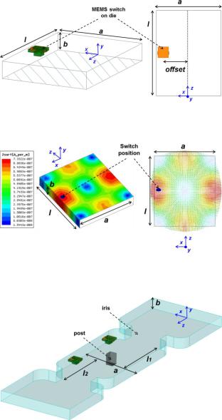
Fig. 1. Two views of the 3-D model of the proposed tunable cavity using MEMS switch on die.
Fig. 2. Current distributions in High-Frequency Structure Simulator (HFSS) of a 


 mode and selected position of the switch in the cavity.
Fig. 3. HFSS 3-D model of the manufactured MEMS-based tunable secondorder filter at  -band.
The most straightforward way to adjust the resonant frequency of a cavity is to perturb the electromagnetic field distribution of the resonant mode(s). The perturbation can be applied to either the EM field or to the current flowing on the inner metal wall of the cavity. In the latter case, the current distribution can be varied by introducing one or more switches located in the region of maximum current amplitude.
In Fig. 1, the MEMS-based tuning principle is applied to a rectangular cavity of length  , width
  and height
  operating at


 mode. The MEMS switch is located in a region of maximum current amplitude, i.e., in the center of the length
  . The switch, connected to the cavity broad wall by ribbon-bonding, is placed above a dielectric substrate of thickness
  and oriented along the current flow, so as to create, when in the ON-state, an
additional current path. The current distribution of the 


 mode (as shown in Fig. 2) is modified depending on the switch state, obtaining two different resonant frequencies. The larger
the ratio 

 between the substrate thickness and the waveguide height, the wider the distance between the two frequencies.
The amount of frequency shift to adjust the filter response can be controlled by changing the ratio 

 and the position of the MEMS on the broad wall with respect to the current maximum. Using a low-loss substrate such as quartz,
  factors up to 1000 can be obtained with a tuning range of 2%. Intermediate frequency shifts can be achieved by using more MEMS switches and separately activating only some of them.
Based on the above tuning concept, Fig. 3 shows the HFSS model of a  -band second-order filter. It consists of two


 -mode cavities coupled by a vertical post and connected to input/output waveguide sections by inductive irises. Each
cavity is loaded with an ohmic MEMS switch, bonded to a broad cavity wall. The MEMS switches are commercially available ohmic switches from RADANT realized on high-resistivity (HR) silicon substrate and based on electrostatic actuation. The
PELLICCIA et al.: HIGH- |
|
TUNABLE WAVEGUIDE FILTERS USING OHMIC RF MEMS SWITCHES |
3383 |
|
MEMS membrane has been modelled in HFSS as 3- series resistance


 when in the ON-state (cantilever down) and as a series capacitance


 of 15 fF in the OFF-state (cantilever up). Such values fit well with the RF measurements of the MEMS.
The two switches are activated simultaneously in order to modify the electromagnetic field and current distribution of the 


 mode inside the cavities and, thus, shift the resonant frequencies. Different tuning ranges can be obtained by varying the position of the MEMS switches inside the cavities along the
  -axis and by changing the cavity height
  . For a
  -band waveguide filter, the shift may range from a few tens of megahertz up to some hundreds of megahertz: the lower
  is, the larger the offset and the frequency shift are . However, the unloaded
  -factor is also affected by the tuning range: the larger thetuning, the lower the
  and the higherthelossin the filter. As the cavity height
  is reduced to achieve larger

 ratios and larger frequency shifts (
 is fixed by the MEMS technology), the quality factor is also reduced. Tuning ranges larger than 2%–3% could also be achieved. However, since the switch activation modifies the filter couplings, additional tuning elements must be used for coupling compensation. Additional frequency states can be obtained using more MEMS per resonator at the expense of higher design complexity and
  reduction (e.g., with
two MEMS the  is roughly 20% lower).
The design procedure of a tunable waveguide filter based on the above concept is described in the following.
First, a single cavity is studied by full-wave simulations (e.g., in eigenmode analysis mode). Its dimensions and the MEMS positions are identified so as to achieve the desired resonant frequencies, thus the required frequency shift, as well as the desired unloaded  s in all states. Next, the filter is designed at the frequency corresponding to the MEMS OFF-state without the presence of MEMS and inherent circuitry, i.e., as a conventional waveguide filter. Couplings between resonators based on central metal discontinuities (such as vertical posts or E-plane septa) are preferred because of their higher coupling stability over frequency compared, e.g., to inductive irises. Once the filter without MEMS is designed, the MEMS and relevant circuitry are included and the filter is simulated in the OFF-state. At this point, a re-optimization is required to compensated for the small frequency shifts as well as variations of the coupling between resonators due to the introduction of the MEMS. Finally, the filter is simulated in the ON-state. If the response does not comply with the requirements, an iterative design procedure can easily be implemented.
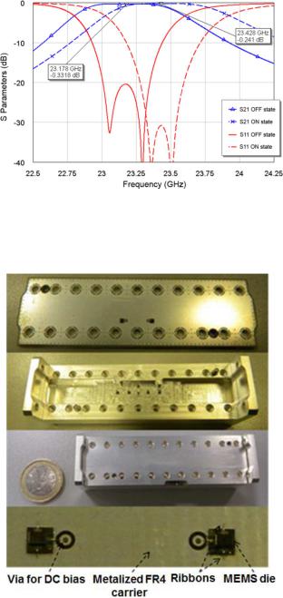
Fig. 4 shows the simulated performances in terms of  -pa- rameters of the second-order filter design in HFSS in the
  -band. When both switches are in OFF-state the filter is centered at 23.178 GHz, showing a 20-dB bandwidth of 1.45%. When the switches are activated, the filter response is shifted upwards and centered at 23.428 GHz (250-MHz shift) while preserving good performance in terms of return loss and bandwidth.
Fig. 5 shows the manufactured filter. It consists of a silverplated WR-42 waveguide length  10.688 mm
  4.318 mm
 . The MEMS switches are glued onto the milled cavity broad wall and electrically connected to the wall using ribbon bonding (see the
Fig. 4. Computed (HFSS)  -parameters of the MEMS-based tunable second-order filter at
  -band in Fig. 3 (


 OFF state: solid blue line with triangle markers;


 OFF state: solid red line without markers;


 ON state: dashed blue line with cross markers;


 ON state: dashed red line without markers).
Fig. 5. Photographs of the manufactured MEMS-based tunable second-order filter at  -band and details of the MEMS die bonding.
photograph at the bottom of Fig. 5). The ribbon introduces parasitic inductances which should be properly considered during the design phase. The MEMS biasing lines are driven by wire bonding to the external part of the filter by vertical vias (visible in the bottom picture of Fig. 5).
The measured 


 parameters are shown in Fig. 6 for both MEMS states. The input RF-power is 0 dBm and the dc bias voltage of the switches is 90 V.
The measured OFF-state resonant frequency is very close to the predictions. The measured frequency shift from ONto OFFstates is 160 MHz 


 . Such a value is smaller than the simulated one (250 MHz) because the bonding ribbons from the MEMS die to the cavity broad wall were longer and thinner

3384 |
IEEE TRANSACTIONS ON MICROWAVE THEORY AND TECHNIQUES, VOL. 63, NO. 10, OCTOBER 2015 |
Fig. 8. HFSS 3-D model of the MEMS-based tunable seventh-order filter at  -band of Fig. 7.
Fig. 6. RF Measured  -parameters of the MEMS-based tunable second-order filter at
  -band of Figs. 3–5 (


 OFF state: solid blue line with triangle markers;


 OFF state: solid red line without markers;


 ON state: dashed blue line with cross markers;


 ON state: dashed red line without markers).
Fig. 7. |
|
-parameters of the MEMS-based |
tunable seventh-order filter at |
|||||
|
||||||||
|
-band based on concept of Fig. 1 ( |
|
|
|
|
OFF-state: solid blue line with |
||
|
|
|
|
|
||||
triangle markers; 


 OFF-state: solid red line without markers;


 ON-state: dashed blue line with cross markers;


 ON-state: dashed red line without markers).
than in the design, thus their actual effect on the resonant mode perturbation is different than what was expected by simulation. This has been proved by post-measurement full-wave simulations based on actual dimensions of the ribbons. The measured  s are about 1000 in the ON-state and 500 in the OFF-state. The larger insertion loss, mainly in the OFF-state is due to the higher


 of the HR silicon. The
  decrease in the OFF-state is due to the loss of the HR silicon of the MEMS substrate and 0-level cap; it could be improved by adopting for the MEMS device a substrate with lower loss, such as quartz. Additional loss may be due to radiation through the vias; this can be minimized by a proper miniaturization.
As a proof of the great potentialities of this approach, Fig. 7 shows the simulated  -parameters of a seventh-order filter design based on the same concept. The expected frequency shift is 252 MHz, and the insertion loss is below 2 dB in both frequency states with 2% fractional bandwidth. The device is being fabricated using only seven MEMS switches on low-loss quartz substrate (i.e., only one switch for each resonator). The HFSS 3-D model of the filter is shown in Fig. 8. As already
Fig. 9. MEMS-based tuning concept proposed in [38] is applied to a waveguide rectangular cavity coupled by E-plane conductive septa.
pointed out, additional MEMS switches can be used to control the bandwidth and the return loss (RL) at the expense of higher design complexity and increased loss.
III. TUNABLE WAVEGUIDE FILTERS WITH VIRTUAL
MOVABLE WALL
A different approachto tunable high- waveguide filters consists of virtually changing the cavity size by activating or deactivating arrays of conductive lines located at the cavity walls [37], [38]. This tuning concept using real RF MEMS switches has been experimentally validated in [39] by designing, manufacturing, assembling, and measuring frequency-tunable singlecavities and filters at 23 GHz. Very satisfactory and promising results have been achieved, particularly in terms of high unloaded
  and robustness of the filter response for a 3%-5% frequency shift.
In the structure of Fig. 9, the MEMS-based tuning principle, proposed in [38], is applied to a rectangular cavity of length  operating at


 mode. Metal E-plane septa of length
  provide at the same time the confinement of the resonant


 mode of the cavity, and its coupling to the


 mode of the guide.
Ohmic cantilever RF MEMS switches fabricated by FBK are series mounted along thin conductive lines connecting the broad waveguide walls. The lines consist of sections connected by RF MEMS ohmic switches, and are fabricated on a low-loss substrate (e.g., quartz) placed at one side wall.
The MEMS are electrostatically actuated by applying a voltage to an electrode (actuation pad). The switch can be

PELLICCIA et al.: HIGH- |
|
TUNABLE WAVEGUIDE FILTERS USING OHMIC RF MEMS SWITCHES |
3385 |
|
Fig. 10. Cavity 


 -mode E-field amplitude with MEMS (a) ON-state and
(b) OFF-state.
(a) |
(b) |
Fig. 11. Photographs of (a) the cantilever MEMS switch and (b) the die containing three lines of switches.
modelled as 1- |
|
series resistance |
|
|
|
|
|
|
when in the ON-state, |
||||||||
|
|
|
|
||||||||||||||
and as a series capacitance |
|
|
|
|
|
|
|
|
|
of 10 fF in the OFF-state. |
|||||||
The tuning principle is based on the effective width 


 of the cavity being varied by opening (OFF-state) or closing (ON-state) the MEMS switches of one or more lines, as shown in Fig. 10.
The amount of frequency shift can be increased by creating an air gap between the substrate and the cavity side wall. The number of MEMS lines and their position affect the frequency shift as well. Intermediate frequency shifts can be achieved by activating only some of the MEMS lines.
One of the main advantages of this tuning approach is the insensitivity of both the filter bandwidth and RL with the frequency tuning, thanks to the negligible variation of the inter-res- onator coupling of the E-plane filter for tuning up to 5%.
Single tunable cavities have been manufactured and tested. Fig. 11 shows the cantilever MEMS switch and the quartz die with three conductive lines, each interrupted by three switches. The comparison between simulated (HFSS)and measured 


 parameters is shown in Fig. 12 for both MEMS states. The input RF power is up to 14 dBm, and the dc bias voltage of the switches is 70 V. The dc power consumption is roughly 0 W.
The measured ON-state resonant frequency is very close to the predictions, with the error around 0.1%. The measured frequency shift from ONto OFFstate is 730 MHz (3.1%); this value is higher than the simulated one (2.6%). This is due to the
Fig. 12. |
Simulated (HFSS) and measured |
|
|
|
parameters of |
one of the |
|
|
|
||||||
|
-band |
tunable cavity prototypes: all MEMS |
|
on (simulated: |
solid blue |
||
|
|
||||||
|
|
||||||
line; measured: dashed blue line); all MEMS off (simulated: dotted red line, measured: dotted–dashed red line).
lower 

 considered in the simulation model of the MEMS. This has been proved by post-measurement simulation of the structure and of the single MEMS. The post-measurement analysis demonstrated the correct value of

 to be 11.5 fF (instead of 10 fF).
The measured unloaded  s are 1450 and 750 for the ONand OFF-states, respectively, whereas the simulated unloaded
  s are 1975 and 1515. The measured ON-state
  is only 25% lower (that is the typical disagreement between simulation and measurement), while the measured OFF-state
  is roughly 50% the simulated one. Such a considerable decrease is to be ascribed to the bias-networks that mainly affect the OFF-state
  . In fact, in the OFF-state, the EM field passes through the quartz die and the bias networks. If the bias-line width is minimized (5
  m instead of 15
  m), the unloaded
  can be increased. This was discovered by post-measurement full-wave simulations. The simulated and measured input/output coupling is 0.04 in the ON-state, whereas it is 0.037 in the OFF-state. Thus, the coupling variation is less than 10%.
The design procedure of a tunable waveguide filter based on the MEMS-based virtual movable wall is described in the following.
First, a single cavity is studied by full-wave simulations. Dimensions and MEMS positions are identified to achieve the required tuning shift and  . The filter is then designed at the frequency corresponding to theMEMS OFF-state withoutthe presence of MEMS and their circuitry, i.e., as a conventional waveguide filter. Once the filter without MEMS has been designed, the MEMS and the relevant circuitry are included in the simulations and the filter is re-optimized in the OFF-state. Finally, the filter is simulated in the ON-state. If the response is not compliant with the requirements, an iterative design procedure can be easily implemented in order to optimize the filter behavior in both states.
The HFSS model and a photograph of a tunable fourth-order bandpass filters at  -band are shown Fig. 13. The HFSS simulations are compared with the measurements in Fig. 14.
The desired frequency shift is 550 MHz 


 , i.e., from 22.175 to 21.625 GHz. As in the single-cavity case, the measured ON-state central frequency is very close to the requirement, while the measured frequency shift from the ONto the OFF-state is larger than the simulated one: 725 MHz


 .
.

3386 |
IEEE TRANSACTIONS ON MICROWAVE THEORY AND TECHNIQUES, VOL. 63, NO. 10, OCTOBER 2015 |
Fig. 15. Broadband measured |
|
|
|
|
|
|
parameters of one the fourth-order |
|
|
|
|
|
|||||
|
-band tunable filter prototypes: |
all |
|
MEMS on (solid blue line); all MEMS |
||||
|
|
|||||||
off (dashed red line). |
|
|
|
|
|
|
|
|
Fig. 13. HFSS design and photograph of one of the manufactured MEMSbased tunable fourth-order bandpass filters for the  -band.
Fig. 16. 3D model of the new proposed MEMS-based tunable filter allowing for three frequency states (in the case of a second-order filter).
Fig. 14. Simulated (HFSS) and measured 


 parameters of one of the fourth-order
  -band tunable filter prototypes: all MEMS on (simulated: solid blue line; measured: dashed blue line); all MEMS off (simulated: dotted red line, measured: dotted–dashed red line).
The measured insertion loss (IL) is higher (0.8 1.3 dB) than the simulated one
 1 dB
1 dB , mainly in the ON-state. It corresponds to a measured average unloaded
  of the tunable resonators above 500 and 650 in the ONand OFF-states, respectively. The average
  degradation with respect to the singlecavity case in both states is due to the manufacturing and assembly of the tunable resonators. It can be observed that the
  in the ON-state of the filter is considerably degraded with respect to that of the OFF-state. This is in contrast with the behavior of the single cavity (Fig. 12), where the
  is better in the ON-state than in the OFF-state. After investigation, we found out that this was due to one of the MEMS switches of the fourth-order filter
showing a higher ON-state resistance so as to compromise the overall  .
.
Fig. 15 shows the broadband measurements of the fourthorder filter in both the MEMS states. The effect of the tuning on the first higher spurious passbands is negligible. The spu- rious-free range (e.g., below 30 dB level) is roughly 40% (i.e., 8.75 GHz) the filter central frequency in the ON-state.
The bandwidth variation from the ONto OFF-state is roughly 10% and the measured RL is above 13 dB in both states. Measurements of the filters have been performed up to 14-dBm RF input power.
In order to improve the performance of such filters, each MEMS line can be fabricated on its own quartz die, so that each line has its individual bias signal. Fig. 16 shows a 3-D HFSS model of a MEMS-tunable second-order E-plane filter with separate line dies. Each resonator employs two MEMS dies, thus six MEMS, and allows for four different states: Die1 Off and Die2 Off, Die1 Off and Die2 On, Die1 On and Die2 Off, and Die1 On and Die2 On. If the dies are symmetrically located with respect to the resonator longitudinal center, three different resonant frequencies are achieved. A longitudinal trench ( 1 mm deep) in the carrier is used underneath the dies to further control the total frequency shift. The deeper the trench, the higher the shift. Frequency shifts above 3% can be reached.
The use of a unique MEMS die allows a single guide and a single carrier (with different biasing via-hole positions as shown

PELLICCIA et al.: HIGH- |
|
TUNABLE WAVEGUIDE FILTERS USING OHMIC RF MEMS SWITCHES |
3387 |
|
Fig. 17. HFSS simulations for three frequency states of a fifth-order filter at  -band using the arrangement shown in Fig. 16. (a) State Off-Off. (b) State Off-On. (c) State On-On. Solid blue lines with triangle markers:


 ; solid
red lines without markers: 


 .
.
in Fig. 16) to be employed for different filter realizations. Only the position of the dies and the E-plane metal foils must be customized for different filters in the same frequency band (e.g., the  -band). The unloaded
  s are still above 1000 according to HFSS simulations.
Such a new configuration has been used to design fifth-order filters at  -band with three different frequency states. The
  -parameters in the three frequency states are shown in Fig. 17.
The largest negative frequency shift is 900 MHz (4%) from 22.35 GHz 


 and the intermediate shift is 450 MHz (2%). The maximum in-band IL is expected to be 2 dB. Still in this new design both RL and BW are quite unchanged after tuning.
Fig. 18. (a) Conventional E-plane resonator. (b) Strip-loaded E-plane resonator.
IV. TUNABLE WAVEGUIDE STRIP-LOADED FILTERS
Another recent concept for tunable bandpass filters leading to very high  s
s


 is presented in this section. The filter is based on rectangular waveguide resonators loaded with thin E-plane metal strips on a low-loss substrate. Ohmic RF MEMS switches are used to modify the lengths of the different metal strips, so as to digitally change the resonant frequency of the fundamental


 mode, thus the filter passband frequency.
To illustrate the tuning principle, let us refer to Fig. 18. In Fig. 18(a), a resonator is shown consisting of a waveguide section comprised by two E-plane septa of length  . The latter quantity determines the input (output) coupling between the


 mode of the guide and the


 resonant mode of the resonator (i.e., an inductive coupling), while the distance
  between the septa determines the resonant frequency of the fundamental


 mode. In Fig. 18(b), additional E-plane conductive thin strips are placed between the septa and used to change the resonant frequency of the


 mode. The thin strips behave as metallic tuning screws located in the region of the E-field maximum of the resonant mode: the longer the strips the lower the resonant frequency. The filter tuning is obtained by varying the lengths of the strips using MEMS switches.
Fig. 19 shows the E-field behaviors when the switches along all of the strips are closed [state 111, Fig. 19(a)], thus the strip are continuous conducting lines, and when all of the switches are open [state 000, Fig. 19(b)] so that the E-field goes through the interrupted conducting lines. In the latter case, the mode perturbation is reduced and the resonant frequency is increased. As a result, the resonant frequency is lowered by switching on the MEMS.
The amount of frequency shift can be controlled by choosing the length and the number of the strips, as well as the distance between them. Intermediate frequency states are allowed switching only some strips, e.g., in the state 010 only the central strip is closed. By increasing the number of states, the  is expected to remain unchanged provided that the number of MEMS is not modified.
Such a filter configuration yields insensitive bandwidth and return loss up to 5% tuning, high- s
s


 in all states and a simple design and fabrication leading to a potentially low-cost manufacturing.
The practical design of a MEMS-based tunable strip-loaded E-plane resonator is illustrated next. The 3-D model design is presented as HFSS model in Fig. 20.
The E-plane circuit pattern (i.e., septa and strips) and the MEMS switchesarerealized ona 500- m-thickquartzsubstrate

3388 |
IEEE TRANSACTIONS ON MICROWAVE THEORY AND TECHNIQUES, VOL. 63, NO. 10, OCTOBER 2015 |
Fig. 21. HFSS simulations for a feasible MEMS-base tunable strip-loaded E-plane fourth-order filter at  -band (


 OFF-state: solid blue line with triangle markers;


 OFF-state: solid red line without markers;


 ON-state: dotted blue line with cross markers;


 ON-state: dotted red line without markers).
TABLE I
COMPARISON OF MEMS-TUNABLE FILTERS
Fig. 19. (a) E-field behavior when the MEMS is on and (b) E-field behavior when the MEMS is off of the fundamental resonant mode of the resonator in Fig. 18.
Fig. 20. HFSS 3-D models for a feasible MEMS-base tunable strip-loaded E-plane resonator: the MEMS and the strips are placed on the septum substrate.
using gold. The strips are 500  m wide. Quartz is preferred over silicon because of its lower permittivity and


 .
.
The quartz protrudes into the waveguide broad wall in order to allow the connection of the MEMS bias lines to the external dc circuitry. Bias lines are realized in high-resistivity polysilicon. The slots opened in the waveguide broad wall are sufficiently thin so as to not interrupt the flowing current (which is zero in the middle of the transverse plane for the 


 mode), thus preventing undesired radiation.
Two ohmic cantilever MEMS switches have been considered in parallel in each strip (i.e., six switches in each resonator), thus the equivalent series resistance is roughly 0.5  in each strip.
The design procedure in this case is similar to the previous cases. Once the resonant cavity is sized, the filter is simulated
first without MEMS, and then an iterative procedure is followed to fulfil the requirements in all frequency states.
Fig.21 showstheHFSS simulationsofafourth-order  -band filter with OFF-state frequency at 22.05 GHz and ON-state frequency at 21.7 GHz, thus the frequency tuning is 0.35 GHz (1.6%). The fractional bandwidths of the filter are 1.8% and 1.6% for OFF-state and ON-state respectively. The insertion loss are expected to be better than 1 dB, corresponding to unloaded
  s of the resonators of the order of 1000. Some prototypes of such filters are being fabricated in the framework of the Eurostar project MEMSET.
V. COMPARISON AND CONCLUSION
MEMS-based tunable waveguide filters can meet the target of minimizing size, mass and manufacturing cost of future terrestrial and satellite systems based on waveguide filter components. To this purpose, three concepts for discrete tunable waveguide filters using ohmic RF MEMS switches allowing for high resonator Qs have been introduced. Table I compares the three proposed tuning concepts based on RF ohmic MEMS switches with other three tuning concepts from the literature; the latter are based on varactor diodes [14], capacitive MEMS switches [25] and varactor MEMS [31].
The first concept (Section II), based on a straightforward perturbation of the resonant mode field distribution, leads to the simplest structure. The number of MEMS per resonator is, in fact, minimized (we use only one MEMS) and the design is simple. On the other hand, the achievable tuning range is lower
PELLICCIA et al.: HIGH- |
|
TUNABLE WAVEGUIDE FILTERS USING OHMIC RF MEMS SWITCHES |
3389 |
|


 than with the other concepts. Higher tuning ranges are achievable using more MEMS but at the expense of lower
  s of the resonators.
The second concept (Section III), based on a virtual movable wall, can provide larger frequency tuning (up to 5% or even above) with  of the order of 1000. The structure is more com-
plex than in the first concept, since it uses several MEMS and a more complex arrangement to drive the bias signal out of the guide without radiation and undesired loss.
The last concept (Section IV) provides intermediate performance between the first two solutions. It is based on strip-loaded waveguide filters with MEMS placed on the E-plane. This concept allows for quite good frequency tuning (1%–5%) with  s above 1000. Also, the technological complexity is intermediate between the other two concepts, thus it can be adopted when a moderate frequency shift is required without adopting a more complex tuning solution as with the second one.
All of our concepts present potentially higher  with respect to the three concepts of the literature. On the other hand, the tuning range of our filters is at most 5% if the
  is above 1000, while higher tuning ranges are obtained by adopting capacitive elements at the expense of lower
  . Our solutions allow only for a discrete tuning, while those based on varactors [14], [31] potentially allow for a continuous tuning.
The three solutions based on ohmic switches have not been tested at high RF power, but the power handling is expected to be of the order of a few watts. Such a limit is intrinsically due to the MEMS components and is valid to all tunable filters based on MEMS or diodes. On the other hand, the linearity of MEMS-based tunable filters is expected to be better than others based on e p-i-n diodes or varactors. In terms of intermodulation performance, our devices have not be tested for this scope, but typical behavior of RF MEMS switches are well described in [40].
Our tuning concepts are suitable for RF systems where a discrete and moderate tuning range is accepted (2%–5%). They can provide also a good robustness of the filter response at different states without any tuning of the filter couplings. Higher tuning rangesareachievableat theexpenseofQdecrease.Adoptingthe concepts in Sections III and IV, the  is in the range 500–1000 for 5%–10% frequency tuning.
ACKNOWLEDGMENT
The authors would like to thank H. El Ghannudi, V. Nocella, and F. Gentili in particular for their contributions. The authors would like to acknowledge Siae Microelettronica for permitting the authors to disclose the experimental results presented in Section II and Ericsson AB for permitting the authors to disclose the experimental results presented in Section III.
REFERENCES
[1]E. Fourn, A. Pothier, C. Champeaux, P. Tristant, A. Catherinot, P. Blondy, G. Tanne, E. Rius, C. Person, and F. Huret, “MEMS switchable interdigital coplanar filter,” IEEE Trans. Microw. Theory Techn., vol. 51, no. 1, pp. 320–324, Jan. 2003.
[2]A. Abbaspour-Tamijani, L. Dussopt, and G. M. Rebeiz, “Miniature and tunable filters using MEMS capacitors,” IEEE Trans. Microwave Theory Tech., vol. 51, no. 7, pp. 1878–1885, Jul. 2003.
[3]A. Ocera, P. Farinelli, P. Mezzanotte, R. Sorrentino, B. Margesin, and
F.Giacomozzi, “A novel MEMS-tunable hairpin line filter on silicon substrate,” in Proc. 36th Eur. Microw. Conf., Sep. 10–15, 2006, pp. 803–806.
[4]P. Blondy, C. Palego, M. Houssini, A. Pothier, and A. Crunteanu, “RF-MEMS reconfigurable filters on low loss substrates for flexible front ends,” in Proc. Asia–Pacific Microw. Conf., Dec. 11–14, 2007, pp. 1–3.
[5]G. Monti, L. Tarricone, and L. Corchia, “MEMS-based filter with a reconfigurable band-pass,” in Proc. 3rd Eur. Conf. Antennas and Propagation, Mar. 23–27, 2009, pp. 445–448.
[6]M. F. Karim, A.-Q. Liu, A. Alphones, and A. Yu, “A reconfigurable micromachined switching filter using periodic structures,” IEEE Trans. Microw. Theory Techn., vol. 55, no. 6, pp. 1154–1162, Jun. 2007.
[7]I.C.HunterandJ.D.Rhodes,“Electronicallytunablemicrowave bandpass filters,” IEEE Trans. Microw. Theory Techn., vol. MTT-30, no. 9, pp. 1354–1360, Sep. 1982.
[8]P. W. Wong and I. C. Hunter, “Electronically tunable filters,” IEEE Microwave Mag., vol. 10, no. 6, pp. 46–54, Oct. 2009.
[9]W. M. Fathelbab and M. B. Steer, “A reconfigurable bandpass filter for RF/microwave multifunctional systems,” IEEE Trans. Microw. Theory Techn., vol. 53, no. 3, pp. 1111–1116, Mar. 2005.
[10]P. W. Wong and I. C. Hunter, “A new class of low-loss high-linearity electronically reconfigurable microwave filter,” IEEE Trans. Microw. Theory Techn., vol. 56, no. 8, pp. 1945–1953, Aug. 2008.
[11]P. W. Wong and I. C. Hunter, “Electronically reconfigurable microwave bandpass filter,” IEEE Trans. Microw. Theory Techn., vol. 57, no. 12, pp. 3070–3079, Dec. 2009.
[12]S. Courreges, Y. Li, Z. Zhao, K. Choi, A. Hunt, and J. Papapolymerou, “Ferroelectric tunable bandpass filters for Ka-band applications,” in Proc. 38th Eur. Microw. Conf., Amsterdam, The Netherlands, Oct. 27–31, 2008, pp. 55–58.
[13]F. He, X. P. Chen, K. Wu, and W. Hong, “Electrically tunable substrate integrated waveguide reflective cavity resonator,” in Proc. Asia–Pa- cific Microw. Conf., Dec. 7–10, 2009, pp. 119–122.
[14]S. Sirci, J. D. Martinez, M. Taroncher, and V. E. Boria, “Varactorloaded continuously tunable SIW resonator for reconfigurable filter design,” in Proc. 41st Eur. Microw. Conf.,Oct.10–13,2011,pp.436–439.
[15]W. Sichak and H. Augenblicki, “Tunable waveguide filters,” in Proc. IRE, Sep. 1951, pp. 1055–1059.
[16]B. Yassini, M. Yu, D. Smith, and S. Kellett, “A k
 -band high-Q tunable filter with stable tuning response,” IEEE Trans. Microw. Theory Techn., vol. 57, no. 12, pp. 2948–2957, Dec. 2009.
[17]A. Djermoun, G. Prigent, N. Raveu, and T. Callegari, “A high Q reconfigurable cavity SIW resonator using a novel perturbation method,” in
Proc. Int. Workshop Microw. Filters, Toulouse, France, Nov. 2009.
[18]J. Uher and W. J. R. Hoefer, “Tunable microwave and millimeter-wave band pass filters,” IEEE Trans. Microw. Theory Techn., vol. 39, no. 4, pp. 643–653, Apr. 1991.
[19]F. Sammoura and L. Lin, “A plastic W-band MEMS tunable filter,” in
IEEE MTT-S Int. Microw. Symp. Dig., 2006, pp. 136–139.
[20]H. Joshi, H. H. Sigmarsson, D. Peroulis, and W. J. Chappell, “Highly loaded evanescent cavities for widely tunable high-Q filters,” in IEEE/ MTT-SInt. Microw. Symp., Jun. 3–8, 2007, pp. 2133–2136.
[21]D. W. Winter and R. R. Mansour, “Tunable dielectric resonator bandpass filter with embedded MEMS tuning elements,” IEEE Trans. Microw. Theory Techn., vol. 55, no. 1, pp. 154–159, Jan. 2007.
[22]R. R. Mansour, “High-Q tunable dielectric resonator filters,” IEEE Microw. Mag., vol. 10, no. 6, pp. 84–98, Oct. 2009.
[23]P. Farinelli, F. Giacomozzi, G. Mannocchi, R. Marcelli, B. Margesin,
P.Mezzanotte, S. Di Nardo, P. Russer, R. Sorrentino, F. Vitulli, and L. Vietzorreck, “RF-MEMS SPDT switch on silicon substrate for space application,” in Top. Meeting Silicon Monolithic Integr. Circuits in RF Syst. Dig. Papers, Sep. 8–10, 2004, pp. 151–154.
[24]S. Kang, H. Cheol Kim, and K. Chun, “Single-pole four-throw RF MEMS switch with double stop comb drive,” in Proc. IEEE 21st Int. Conf. Micro Electro Mech. Syst., Jan. 13–17, 2008, pp. 1036–1039.
[25]S. J. Park, I. Reines, C. Patel, and G. Rebeiz, “High-Q RF-MEMS 4–6 GHz tunable evanescent-mode cavity filter,” IEEE Trans. Microw. Theory Techn., vol. 58, no. 2, pp. 1145–1148, Feb. 2010.
[26]H. Joshi, H. H. Sigmarsson, S. Moon, D. Peroulis, and W. J. Chappell, “High-Q fully reconfigurable tunable bandpass filter,” IEEE Trans. Microw. Theory Techn., vol. 57, no. 12, pp. 3525–3533, Dec. 2009.
[27]J. Xu, X. P. Liang, and K. Shamsaifar, “Full wave analysis and design of RF tunable filters,” in IEEE MTT-S Int. Microw. Symp. Dig., May 2001, vol. 3, pp. 1449–1452.
[28]D. Scarbrough, C. Goldsmith, J. Papapolymerou, and Y. Li, “Miniature microwave RF MEMS tunable waveguide filter,” in Proc. Eur. Microwave Conf., Oct. 2009, pp. 1860–1863.

3390 |
IEEE TRANSACTIONS ON MICROWAVE THEORY AND TECHNIQUES, VOL. 63, NO. 10, OCTOBER 2015 |
[29]R. Stefanini, M. Chatras, A. Pothier, J. C. Orlianges, and P. Blondy, “High Q tunable cavity using dielectric less RF-MEMS varactors,” in Proc. Eur. Microw. Conf., Rome, Italy, Oct. 1, 2009, pp. 1744–1747.
[30]R. Stefanini, J. D. Martinez, M. Chatras, A. Porthier, V. Boria, and P. Blondy, “13 GHz high-Q tunable surface mounted cavity,” in Proc. Int. Workshop Microw. Filters, Toulouse, France, 2009.
[31]R. Stefanini, J. D. Martinez, M. Chatras, A. Pothier, V. E. Boria, and P. Blondy, “
 -band high Q tunable surface-mounted cavity resonator using RF MEMS varactors,” IEEE Microw. Wireless Compon. Lett., vol. 21, no. 5, May 2011.
[32]F. Sammoura and L. Lin, “A plastic W-band MEMS tunable filter,” in
IEEE MTT-S Int. Microw. Symp. Dig., , 2006, pp. 136–139.
[33]H. Joshi, H. H. Sigmarsson, D. Peroulis, and W. J. Chappell, “Highly loaded evanescent cavities for widely tunable high-Q filters,” in IEEE/ MTT-S Int. Microw. Symp., Jun. 3–8, 2007, pp. 2133–2136.
[34]D. W. Winter and R. R. Mansour, “Tunable dielectric resonator bandpass filter with embedded MEMS tuning elements,” IEEE Trans. Microw. Theory Techn., vol. 55, no. 1, pp. 154–159, Jan. 2007.
[35]R. R. Mansour, “High-Q tunable dielectric resonator filters,” IEEE Microw. Mag., vol. 10, no. 6, pp. 84–98, Oct. 2009.
[36]W. D. Yan and R. R. Mansour, “Micromachined millimeter-wave ridge waveguide filter with embedded MEMS tuning elements,” in IEEE- MTT-SInt. Microw. Symp. Dig., Jun. 11–16, 2006, pp. 1290–1293.
[37]P. Ligander, O. Persson, L. Pelliccia, S. Bastioli, and R. Sorrentino, “An Electrically Tunable Waveguide Filter and Waveguide Tuning Devices,International Publication N.: WO 2012/016584 A1; International Application N.: PCT/EP2010/061218, International Filing Date: 2nd August 2010, International Publication,” , Feb. 9th, 2012.
[38]L. Pelliccia, S. Bastioli, F. Casini, and R. Sorrentino, “High-Q MEMSreconfigurable waveguide filters,” in Proc. 40th EuMC, Paris, France, Sep.-Oct. 2010, pp. 1126–1129.
[39]L. Pelliccia, F. Cacciamani, P. Farinelli, P. Ligander, O. Persson, and R. Sorrentino, “High-Q MEMS-tunable waveguide filters in K-band,” in Proc. 42nd Eur. Microw. Conf., Amsterdam, The Netherlands, Nov. 2012, pp. 273–276.
[40]L. Dussopt and G. M. Rebeiz, “Intermodulation distortion and power handling in RF MEMS switches, varactors, and tunable filters,” IEEE Trans. Microw. Theory Techn., vol. 51, no. 4, p. 1247, 1256, Apr. 2003.
Luca Pelliccia received the Laurea (with distinction) and Ph.D. degrees in electronic engineering from the University of Perugia, Perugia, Italy, in 2009 and 2012, respectively. His dissertation was titled “Tunable and miniaturized waveguide filters for advanced communication systems” carried out under Prof. Roberto Sorrentino.
In 2008–2009, he carried out his thesis research with Ericsson AB, Mölndal, Sweden. He is currently with RF Microtech Srl (whose he is associate member), Perugia, Italy, as a Designer and Manager
of the Microwave Filter and Passive Components area. His research activities include innovative concepts for miniaturized, tunable waveguide filters. His research involvement has resulted in the publication of several papers in the proceedings of international microwave conferences and journals.
Fabrizio Cacciamani received the Laurea degree in electronic engineering from the University of Perugia, Perugia, Italy, in 2009.
In February 2010, he joined the Department of Electronic and Information Engineering (DIEI), University of Perugia, Perugia, Italy, under the advice of Prof. Roberto Sorrentino. For the last three years he has collaborated with RF Microtech, Perugia, Italy, in several international research projects concerning RF MEMS, microwave bandpass filter and antenna design. His research activities include: development
and design of reflectarray antennas radiating element and microwave filters.
Paola Farinelli received the Laurea (with distinction) and Ph.D. degrees in electronic engineering from the University of Perugia, Perugia, Italy, in 2002 and 2006, respectively.
She has been involved in different European projects (ESA projects, Network of excellence, FP7 projects) which enabled close collaborations with many industrial and academic research institutes. She is currently leading the RF MEMS Research and Development unit at RF Microtech, Perugia, Italy. Her research activity focuses on the electromagnetic
modelling and design of reconfigurable RF MEMS components and circuits.
Roberto Sorrentino (LF’90) is a Professor with the University of Perugia, Perugia, Italy. His research activity deals with the analysis and design of microwave and millimeter-wave circuits and antennas. He has authored or coauthored more than 150 technical papers in international journals, 300 refereed conference papers, and three books.
Prof. Sorrentino was a recipient of the IEEE Microwave Theory and Techniques Society (MTT-S) Meritorious Service Award (1994), the IEEE Third Millennium Medal (2000), the Distinguished Edu-
cator Award from IEEE MTT-S (2004), and the MTT-S Microwave Career Award (2015). He was the Editor-in-Chief of the IEEE MICROWAVE AND GUIDED WAVE LETTERS (1995 –1998) and was among the founders and President of the European Microwave Association (1998–2009).