

диафрагмированные волноводные фильтры / 9aa43365-015b-4d2b-ace8-b8def9f0d29f
.pdfAccepted Manuscript
Regular paper
Offset-fed Complementary Split Ring Resonators loaded monopole antenna for multiband operations
R. Samson Daniel, R. Pandeeswari, S. Raghavan
PII: |
S1434-8411(17)30798-7 |
|
DOI: |
http://dx.doi.org/10.1016/j.aeue.2017.05.016 |
|
Reference: |
AEUE 51887 |
|
To appear in: |
International Journal of Electronics and Communi- |
|
|
cations |
|
Received Date: |
4 April 2017 |
|
Revised Date: |
26 |
April 2017 |
Accepted Date: |
10 |
May 2017 |
Please cite this article as: R.S. Daniel, R. Pandeeswari, S. Raghavan, Offset-fed Complementary Split Ring Resonators loaded monopole antenna for multiband operations, International Journal of Electronics and Communications (2017), doi: http://dx.doi.org/10.1016/j.aeue.2017.05.016
This is a PDF file of an unedited manuscript that has been accepted for publication. As a service to our customers we are providing this early version of the manuscript. The manuscript will undergo copyediting, typesetting, and review of the resulting proof before it is published in its final form. Please note that during the production process errors may be discovered which could affect the content, and all legal disclaimers that apply to the journal pertain.

Offset-fed Complementary Split Ring Resonators loaded
monopole antenna for multiband operations
Samson Daniel. R1*, Pandeeswari. R2, Raghavan. S3
123Department of Electronics and Communication Engineering,
National Institute of Technology, Trichirappalli 620015, India
samson.rapheal@gmail.com1*, rpands@nitt.edu2, raghvan@nitt.edu3
Abstract
A miniaturized multiband monopole antenna based on rectangular-shaped Complementary Split Ring Resonators (CSRRs) with offset-fed microstrip line is proposed for Global System for Mobile Communication (GSM) and Wireless Local Area Network (WLAN) applications. The proposed antenna is fabricated on a FR-4 substrate having a dielectric constant (ε ) of 4.4 within a small size of 19.18 ×22.64 × 1.6 mm3. CSRRs in the
monopole antenna create a multiband characteristics and bandwidth improvement, which is analyzed by use of the precise quasi-static design equations and electromagnetic simulation software (HFSS version 13). By selecting a proper offset-fed microstrip line, it is capable to achieve 50 characteristic impedance and good impedance matching. The parameter extraction procedure of the metamaterial property of the CSRRs is enlightened in detail, by which the negative permittivity existence and the new resonance frequencies are verified. Simulated and measured result coincides with each other. The measured H-Plane (azimuthal plane) exhibits omnidirectional radiation pattern and E-plane (elevation plane) shows a dipole like bidirectional radiation pattern. The proposed antenna has adequate advantages, including simple design, small size, lower return loss and capable of multiband operations.
Key words
CSRRs, GSM, Multiband, Negative Permittivity, Offset-fed, WLAN.
*Corresponding Author Email Address:
R. Samson Daniel: samson.rapheal@gmail.com

1. Introduction
Metamaterial is an artificial effectively homogeneous Electromagnetic (EM) structure with unusual properties not readily available in nature, with average cell size smaller than a quarter of a wavelength (P< ) [1]. Many antenna designers have spurred metamaterial
antennas in millimeter wave frequency bands due to its extraordinary EM properties. CSRR based metamaterial can be used to design microwave components such as branch line coupler [2], body-worn communication devices [3], filters [4] and multiband antenna design [5, 6]. The Structural alignment of CSRR alters the current direction and contributes the new resonance frequency with respect to band pass filter [7]. CSRR employs the negative permittivity ( ) characteristics through a band pass filter. The application of CSRR becomes more attractive due to sub wavelength resonator, such as miniaturization [8] and gain improvement [9]. Electric-field-Coupled resonator (ELC) based metamaterial exhibits negative permittivity and eliminates cross polarization [10]. For high frequency microwave applications such as radar and point-to-point communications Substrate Integrated Waveguide (SIW) technology is used to reduce the side lobe level [11] and phase correction [12]. PIN diode controls the DC bias currents [13] for achieving reconfigurable antenna design [14].
In this paper, an offset-fed CSRR loaded monopole antenna is proposed for GSM (1.86−1.91 GHz) and WLAN (2.89−2.98 GHz), and (4.96−6.78 GHz) applications. The resonance frequency of CSRR and its permittivity characteristics are investigated to confirm the results. A good method has utilized to attain good impedance matching and multiband characteristics within a compact antenna geometry. This paper has got special interest, which includes a quasi-static equivalent circuit analysis of CSRR resonance frequency and compared with previously reported antennas [6, 8, 10, 15−17].
2. Proposed antenna geometry and simulated results
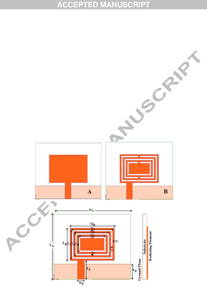
The proposed antenna is developed from a broadband rectangular monopole antenna as shown in conventional antenna (A) of Fig. 1. This conventional antenna created a broadband from 2.73 GHz to 6.52 GHz. In the next step, CSRRs and offset-fed microstrip line is introduced to achieve multiband and good impedance matching as shown in proposed antenna (B) of Fig. 1. CSRR is useful for creating a new resonance frequency corresponding to the CSRR geometrical values. The CSRR slot width (S) and the slit between the slots (S1)
are fixed constant for simplicity. Now, the proposed antenna offers two lower frequencies for realizing miniaturization. The geometry of the proposed antenna is depicted in Fig. 2. The parameters of an antenna are listed in Table 1. The snapshot of the fabricated antenna is shown in Fig. 3.
Fig. 1. Design steps of the proposed antenna.
Fig. 2. (a) Proposed antenna geometry and its side view.

Fig. 3. Snapshot of the fabricated proposed antenna (top view and bottom view). Table 1 Parameters of the Proposed Antenna
Parameter |
Dimension (mm) |
Parameter |
Dimension (mm) |
|
|
|
|
L |
19.18 |
L |
5.58 |
W |
22.64 |
W |
9.04 |
L |
5.51 |
L |
3.58 |
W |
2 |
W |
7.04 |
W |
13.04 |
W |
0.5 |
L |
9.58 |
S |
0.5 |
L |
7.58 |
S |
0.5 |
W |
11.04 |
L |
4.5 |
The simulated return loss characteristics of the conventional antenna (A) and proposed antenna (B) are shown in Fig. 4. It is observed that the prototype antenna shows triple resonance at 1.98 GHz, 3.03 GHz and 5.5 GHz. This multiband is obtained by CSRR rings and the slit in them. These results are confirmed by investigation on the CSRR rings under three cases: (a) Single ring CSRR (N=1), (b) Double ring CSRR (N=2), (c) Triple ring CSRR (N=3). Fig. 5 illustrates the return loss characteristics of the number of CSRR rings with a corresponding inset picture which explains their CSRR geometries. It is inferred that a new resonance frequency of 6 GHz, 1.98 GHz and 3.03 GHz are achieved to the case N=1, N=2, and N=3 CSRR geometries, respectively. Also, it is found that, the number of CSRR rings

increases the upper frequency is affected more and generates the dual resonance frequency of 5.18 GHz and 6.16 GHz with center frequency of 5.5 GHz.
Fig. 4. Simulated return loss characteristics of the conventional antenna and proposed antenna.
Fig. 5. Simulated return loss characteristics of the number of CSRR rings (a) Single ring CSRR (N=1), (b) Double ring CSRR (N=2), and (c) Triple ring CSRR (N=3).

The comparison between previously reported metamaterial antennas with a proposed
antenna as described in Table 2. It is understood that, the prototype antenna covers the least
possible area to achieve multiband antenna for GSM and WLAN applications. In addition, this
paper highlights the evidence of metamaterial property (negative permittivity) for creating a
new resonance frequency.
Table 2 Comparisons of previously reported antennas with proposed antenna.
Reference |
Patch Detail |
Dimensions |
Frequency |
Quasi-static |
Metamaterial |
|
|
L×W |
(GHz) |
Analysis |
property |
|
|
(mm2) |
|
|
verification |
[6] |
Pentagon |
34 × 32 |
3.2, 4.5, and |
Not Computed |
Not Verified |
|
patch and |
|
6 |
|
|
|
CSRRs |
|
|
|
|
[8] |
CPW-fed two |
30 × 20 |
5.63 |
Not Computed |
Not Verified |
|
CSRRs |
|
|
|
|
[10] |
Square ELC |
30 × 21 |
3.28 to 4.52 |
Not Computed |
Not Verified |
|
|
|
and 5.20 to |
|
|
|
|
|
5.87 |
|
|
[15] |
Rectangular |
34 × 30 |
2.4, 3.3, and |
Not Computed |
Not Verified |
|
patch and |
|
5.2 |
|
|
|
CSRR |
|
|
|
|
[16] |
metamaterial |
30 × 30 |
2.4, 3, and |
Not Computed |
Not Verified |
|
unit cell |
|
5.7 |
|
|
[17] |
CSRR loaded |
26.27 × 31 |
3.4, 5.1, and |
Not Computed |
Not Verified |
|
ground plane |
|
9.5 |
|
|
Proposed |
|
19.18 × 22.64 |
1.98, 3.03, |
Computed |
Verified |
antenna |
|
|
and 5.18 to |
|
|
|
|
|
6.16 |
|
|
|
|
|
|
|
|

3. Parametric study
Parametric study is done on the return loss characteristics for the various microstrip feed position, ground plane length (L ) and slit effect on the CSRR. To ensure good impedance
matching, the microstrip feed position is examined in the right offset and left offset from the center feed position. The characteristic impedance 50 Ω is inferred for left offset microstrip line, which is shown in Fig. 6. The ground plane length, L , is varied from 7.5 mm to 4.5 mm,
in steps of 1 mm, as shown in Fig. 7. Due to impedance mismatch at upper most frequency with dual resonance (5.17 GHz and 6.15 GHz) is affected more. However, the better impedance matching for the dual resonance is obtained at the length (L ) of 4.5 mm.
Fig. 6. Simulated return loss characteristics of various microstrip feed position.

Fig. 7. Simulated return loss for various length of the ground plane (Lg).
Also, parametric study is done on the slit effect on CSRRs, as shown in Fig. 8. It is found that, CSRRs without slit is not generated electric resonance for creating a new resonance frequency and bandwidth enhancement. However, CSRRs with slit induces a pass band (S11) in the S-parameters due to presence of narrow electric resonance. Thus, it is responsible for generating multiband and bandwidth enhancement.
Fig. 8. Slit effects on CSRRs.

4. Quasi-static analysis of CSRR
The CSRR resonance frequency is analyzed by quasi-static equivalent circuit model [18], as described in Fig. 9. Slit gap plays a major role in creating pass band characteristics. The capacitance of CSRR (CCSRR) is governed by slot among the metal strip and inductance of
CSRR (LCSRR) is governed by a metal strip among the slot.
Fig. 9. Proposed CSRR and its equivalent circuit model.
The application of babinet principle constructs the execution of its CSRR. Thus, the
CSRR resonance frequency (fCSRR) is computed by [19].
|
|
|
|
|
|
|
|
|
|
|||
|
= |
|
|
|
|
(1) |
||||||
|
|
|
|
|
|
|||||||
|
!! !! |
|
||||||||||
" = |
#$ |
[2L-(2N-1) (W+S)]"% |
|
|||||||||
|
|
|
||||||||||
|
|
|
|
|
|
|
|
|
|
|
|
|
|
((* |
|
) |
|
|
|
|
/ |
|
|
|
|
"% = '% |
$(+ |
and . = |
|
|
|
|||||||
((-) |
|
|
|
|
|
|
||||||
|
|
|
|
|
|
|
01 / |
|
|
|||
|
|
|
|
|
|
|
|
|
|
|
|
|
2 = 4µ %[L-(N-1) (S+W)] [ln (%.645) +1.847]
7(#$ )(01 )
=$(#$ )(01 )
Here, N is the number of CSRR rings (N), Average length of the CSRR ring (L), Width of the slot (W) = 0.5 mm, distance between the slots (S) = 0.5 mm and K is the first order elliptic