

диафрагмированные волноводные фильтры / 8ad7d3ca-13be-4162-a618-4bdb3dc3c3c2
.pdfReceived: 12 February 2021
DOI: 10.1002/mop.32915
R E S E A R C H A R T I C L E
Flexible design of W-band bandpass filter with multiple transmission zeros
Zhao-Yu Huang |
| |
Yun Jiang |
| |
Jing-Jian Huang |
| |
Wei-Dong Hu |
| |
Nai-Chang Yuan |
|
|
|
College of Electronic Science and Technology, National University of
Defense Technology, Changsha, China
Correspondence
Jing-Jian Huang, College of Electronic Science and Technology, National University of Defense Technology, Deya Road 109, Changsha 410073, China.
Email: hjjfh2003@aliyun.com
Abstract
In this paper, a novel E-plane waveguide bandpass filter with multiple transmission zeros is proposed in W-band. The center frequency and bandwidth of this filter can be flexibly designed. Stripe line resonators and L-shaped resonators are used in the filter. The filter contains four resonators, two of which are used to generate transmission zeros in the upper stopband, and the other two are used to generate transmission zeros in the lower stopband. These transmission zeros can enhance the out- of-band suppression and selectivity of the filter. And the position of the transmission zeroes can be flexibly changed as required. One sample is fabricated and measured to verify the proposed filter. The minimum insertion loss in passband is 0.6 dB. Good agreements between the simulated and measured results are achieved.
K E Y W O R D S
E-plane, flexible design, transmission zeros, W band, waveguide
bandpass filter
bandwidth, and strong anti-jamming ability. Filter is one of the important passive components, which affects the performance of communication systems. In W-band, waveguide filters are widely used because of the superiorities of high cavity quality (Q) value, low loss and high power capacity compared to microstrip filter.1–3 The common structure of waveguide filters is that multiple resonant cavities are arranged in a straight line,4,5 and the coupling between resonant cavities is adjusted by controlling the size of inductive or capacitive irises. Cross-coupling can be achieved by changing the arrangement of resonant cavities, which produces transmission zeros and improves the selectivity of the filter.6–8 However, it is undeniable that the size of the waveguide filter is generally large, the fabrication is complicated and the cost is relatively high. And it is not conducive to the miniaturization and mass production. How to achieve the miniaturization of waveguide filters while ensuring good performance is a problem that needs to be solved. The waveguide E-plane septum filter was firstly introduced by Konishi and Uenakada.9 This filter is realized by adding a metal septum to the E-plane of the waveguide. Compared with multi-cavity structures, the size of it and processing complexity are reduced. Some novel E-plane waveguide filters are proposed based on the design method.10–14 In many designs, the metal septum is replaced by the printed circuit structure, which improves design flexibility. In Reference 15, C-shaped resonators and central-folded stripline resonators were utilized to bring transmission zeros. And a waveguide filter based on electromagnetically induced transparency structure (a kind of printed circuit) was introduced in Reference 16.
In this article, a novel E-plane filter with stripe line resonators and L-shaped resonators is proposed. These resonators can produce multiple transmission zeros, and the positions of these transmission zeros can be adjusted as required. Thus, the flexible design of the center frequency and bandwidth of the filter is realized. The length of the printed circuit loaded in the waveguide is only 2.6 mm, which meets the requirements of miniaturized design.
1 | INTRODUCTION
W-band communication systems have been paid special
attention because of their high integration, wide application
2 | DESIGN AND ANALYSIS OF THE PROPOSED FILTER
In this section, the design theory and procedures of the proposed filter are presented and analyzed. When only one dielectric substrate is loaded in the E-plane waveguide without other circuits, its frequency response shows through
Microw Opt Technol Lett. 2021;1–4. |
wileyonlinelibrary.com/journal/mop |
© 2021 Wiley Periodicals LLC. |
|
1 |
|

2 |
|
|
HUANG ET AL. |
|
|
||
|
|
|
|
FIGURE 1 Structure of E-plane waveguide filter. (A), Loaded circuit;
(B), Fabrication structure [Color figure can be viewed at
wileyonlinelibrary.com]
characteristics in W band. Next, transmission zeros are introduced separately in the lower frequency band and higher frequency band, and then combined to form the E-plane waveguide filter. The passband of the filter appears between the lower and higher transmission zeros.
The printed circuit loaded on the E-plane waveguide filter is shown in Figure 1(A). It contains four grounded resonators, two of which are strip line and the other two are L- shaped line. The four resonators are connected to two rows of metalized ground vias. In order to fix the printed circuit in the midplane of the waveguide, the width of the circuit needs to be enlarged, where is the location of the vias. The metalized vias not only realize the grounding of the resonators, but also form an electric wall to prevent the leakage of electromagnetic waves. The substrate of this circuit is Duriod 5880 (thickness = 0.127 mm, εr ¼2:2), and the thickness of metal circuit is 0.017 mm. Figure 1(B) presents the fabrication structure. In order to facilitate measuring, the printed circuit is loaded into a standard WR-10 waveguide with the length of 13 mm. The four resonators in the filter can all be regarded as quarter-wave resonators with lengths of slightly less than λg=4, where λg is the waveguide wavelength.
The two stripe line resonators introduce two transmission zeros in the upper stopband, meanwhile the two L-shaped resonators generate two transmission zeros in the lower
stopband. When the filter contains only two L-shaped resonators, its frequency response exhibits high-pass characteristic. And the position of the transmission zeros can be adjusted by parameter l3 as shown in Figure 2(A). The two transmission zeros move to low frequency as l3 increases. Moreover, two stripe line resonators make the frequency response of the filter appear low-pass characteristic. As shown in Figure 2(B), the position of two transmission zeros in upper stopband moves to high frequency as l2 decreases. In the design, positions of transmission zeros in both upper and lower stopband can be determined according to the requirements of the center frequency and bandwidth.
FIGURE 3 Simulation results of the filter under different parameters. (A), The amplitude of S21 versus l2, (B), The amplitude of S21 versus l3 [Color figure can be viewed at wileyonlinelibrary.com]
FIGURE 2 Simulation results of waveguide loaded with L-shaped resonators or stripe line resonators. (A), L-shaped resonators versus l3, (B), Stripe line resonators versus l2 [Color figure can be viewed at wileyonlinelibrary.com]
HUANG ET AL. |
|
3 |
|
|
|
||
|
|
|
|
The combination of stripe line and L-shaped resonators forms a bandpass filter. The two types of resonators are distributed on the upper and lower parts of the substrate in the X direction as shown in Figure 1(A). The addition of tripe line resonators makes the positions of the two transmission zeros at the lower stopband closer, thus becoming one transmission zero point. The separation of the two transmission zeros in the upper stopband or the lower stopband is affected by the dielectric constant of the substrate. Next, the influences of parameter l2 and parameter l3 on the center frequency and bandwidth of filter are analyzed. We only adjust l2 or l3, and fix the other parameters. It can be seen from the Figure 3(A) that the cutoff frequency of the filter at high frequencies decreases as l2 increases, while the cutoff frequency at low frequencies is almost unchanged. And the 3-dB bandwidth is from 7.4 to 3.8 GHz. Moreover, Figure 3
(B) presents the simulated frequency response versus l3. The cutoff frequency at low frequencies increases as l3 decreases, while the cutoff frequency at high frequencies is almost unchanged. The 3-dB bandwidth is from 9.2 to 7 GHz. In this way, the flexible adjustment of center frequency and bandwidth is realized. The width of lines in the printed circuit is 1 mm. The parameter s1 and s2 influence the position of transmission poles, which can be optimized according to demand.
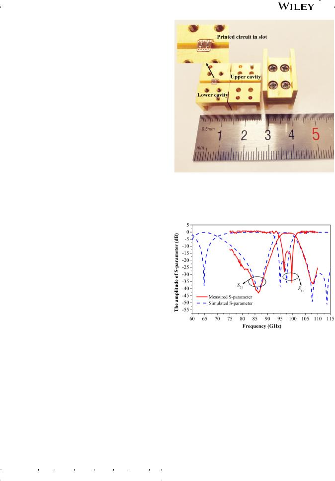
FIGURE 4 Photograph of a fabricated filter [Color figure can be viewed at wileyonlinelibrary.com]
3 | FABRICATION AND EXPERIMENT
In order to verify the proposed filter, one sample is fabricated and measured. The dimension of printed circuit is shown in Table 1. Figure 4 shows the photograph of the fabricated filter. The printed circuit is placed in the slot of the lower cavity. In order to facilitate the connection with the vector network analyzer, a standard waveguide with a total length of 13 mm is used to feed the filter. The measurement frequency range of the vector network analyzer is 75–110 GHz.
Figure 5 describes the simulated and measured results. Transmission zeros contribute to the sharp attention and high selectivity outside the passband. A frequency shift of 1.25 GHz (1.28%) is observed between the simulated and measured results. The measured center frequency is 98 GHz with 3-dB fractional bandwidth of 6.9% and the minimum insertion loss in the passband is 0.6 dB. Moreover, the S11 in the passband is less than 13 dB. The reason for the difference between measured and simulated
TABLE 1 |
Dimensions of printed circuit (mm) |
|
|
||||
|
|
|
|
|
|
|
|
Parameter |
l1 |
l2 |
l3 |
l4 |
s1 |
s2 |
w |
Value |
2.6 |
0.52 |
0.44 |
0.43 |
0.9 |
0.98 |
1.27 |
|
|
|
|
|
|
|
|
FIGURE 5 Measured and simulated results of the fabricated filter [Color figure can be viewed at wileyonlinelibrary.com]
results is the inaccuracies of manufacturing, assembling and measurement. Table 2 presents a comparison between some other W-band bandpass filters and the proposed structure. The proposed filter has a smaller size while showing excellent performance.
Finally, we would like to figure out that there is a parasitic passband locating below our designed passband, and it may deteriorate the stopband characteristics. The reason is that the position of the parasitic passband is far away from the position of the transmission zeros, and the transmission zeros cannot suppress it. A new resonator could be added to the filter to improve the out-of-band rejection when needed in practical application.

4 |
|
|
|
|
|
|
|
|
HUANG ET AL. |
|
|
|
|
|
|
|
|
||
|
|
|
|
|
|
|
|||
TABLE 2 |
Comparison between the proposed and referenced filters |
|
|
|
|||||
|
|
|
|
|
|
|
|
|
|
Reference |
CF (GHz) |
FBW (%) |
IL (dB) |
No. of TZs |
Length (mm) |
Form |
|||
4 |
|
|
92.5 |
20 |
0.6 |
1 |
— |
Waveguide |
|
|
|
|
|
|
|
|
|
|
|
1 |
|
|
80 |
|
2.5 |
3.89 |
1 |
— |
SIW |
13 |
|
|
82.7 |
6 |
0.41 |
0 |
18.8 |
E-plane Waveguide |
|
|
|
|
|
|
|
|
|
|
|
14 |
|
|
93 |
|
2.1 |
2 |
0 |
7.89 |
E-plane Waveguide |
This work |
98 |
|
6.9 |
0.6 |
3 |
2.6 |
E-plane Waveguide |
||
|
|
|
|
|
|
|
|
|
|
Note: Length, the length of the loaded circuit.
Abbreviations: CF, center frequency; FBW, fractional bandwidth; IL, the minimum insertion loss.
4 | CONCLUSION
This paper has presented a novel E-plane waveguide filter in W band. Stripe line and L-shaped resonators are used to produce transmission zeros in the stopband of the proposed filter, which improves the out-of-band rejection and the selectivity of the passband. In this design, the center frequency and bandwidth of the filter can be flexibly adjusted by changing the size of the resonators. A sample of the proposed E-plane waveguide filter is fabricated and tested, and the minimum insertion loss is only 0.6 dB, showing excellent performance. The pattern of the resonators is simple so that the risk of manufacturing errors is reduced, and it is suitable for mass production.
ORCID
Zhao-Yu Huang https://orcid.org/0000-0002-3528-8281
REFERENCES
[1]Hao Z, Ding W, Hong W. Developing low-cost w-band siw bandpass filters using the commerciallyavailable printed-circuit-board technology. IEEE Trans Microwave Theory Tech. 2016;64(6): 1775-1786.
[2]Zhou K, Ding J, Zhou C, Wu W. W-band dual-band quasi-elliptical waveguide filter with flexibly allocated frequency and bandwidth ratios. IEEE Microw Wirel Compon Lett. 2018;28(3):206-208.
[3]Chen JF, Chao Zhang SZ, Li YH. W-band dual-band waveguide band-pass filter using dual-mode cavities. Electron Lett. 2018;54 (25):1444-1445.
[4]Xu J, Ding JQ, Zhao Y, Ge JX. W-band broadband waveguide filter based on H-plane offset coupling. J Infrared, Millimeter, Terahertz Waves. 2019;40(4):412-418.
[5]Dad VK, Gupta S. Design and performance comparison of a novel high Q coaxial resonator filter and compact waveguide filter for millimeter wave payload applications. Int J RF Microw Comput Aided Eng. 2019;29:e21773.
[6]Ding JQ, Liu D, Shi SC, Wu W. W-band quasi-elliptical waveguide filter with cross-coupling and source–load coupling. Elec-
tron Lett. 2016;52(23):1960-1961.
[7]Bai Q, Zhang BZ, Duan JP. Design of W band rectangular waveguide filter. IEEE 9th International Conference on Communication Software and Networks (ICCSN), 2017; Guangzhou, China.
[8]Song S, Yoo C, Seo K. W-band bandpass filter using micromachined air-cavity resonator with current probes. IEEE Microw Wirel Compon Lett. 2010;20(4):205-207.
[9]Konishi Y, Uenakada K. The Design of a Bandpass Filter with inductive strip - planar circuit mounted in waveguide. IEEE Trans Microw Theory Tech. 1974;22(10):869-873.
[10]Xu ZB, Guo J, Qian C, Dou WB. Broad-band E-plane filters with improved stop-band performance. IEEE Microw Wirel Compon Lett. 2011;21(7):350-352.
[11]Bod M, Hatefi AH. A dual-mode waveguide filter based on stereometamaterial CSRR resonator. Microw Opt Technol Lett. 2018;60:3003-3006.
[12]Jin JY, Lin XQ, Jiang Y, Wang L, Fan Y. A novel E-plane substrate inserted bandpass filter with high selectivity and compact size. Int J RF Microw Computer-Aided Eng. 2014;24(4):451-456.
[13]Zhao MH, He ZR, Fan Y, Zhang YH. A W-band wideband E- plane type waveguide bandpass filter. 2015 8th UK, Europe, China Millimeter Waves and THz Technology Workshop (UCMMT), Sept 2015, Cardiff, UK.
[14]Wu WJ, Zhang R, Fan XX. A high stop-band suppression W-band waveguide E-plane filter for millimeter-wave applications. 2016 IEEE International Conference on Microwave and Millimeter Wave Technology (ICMMT), June 2016, Beijing, China.
[15]Jin J-Y, Lin X-Q, Jiang Y, Xue Q. A novel compact-plane wave-
guide filter with multiple transmission zeroes. IEEE Trans Microw Theory Tech. 2015;63(10):3374–3380.
[16]Lin X-Q, Jin J-Y, Jiang Y, Fan Y, Xue Q. Design and analysis of EMIT filter and diplexer. IEEE Trans Ind Electron. 2017;64(4): 3059-3066.
How to cite this article: Huang Z-Y, Jiang Y, Huang J-J, Hu W-D, Yuan N-C. Flexible design of W-band bandpass filter with multiple transmission zeros. Microw Opt Technol Lett. 2021;1–4. https:// doi.org/10.1002/mop.32915