

диафрагмированные волноводные фильтры / 7fa4666a-f3c8-4bc8-ac88-d86a0b975cf9
.pdfThis article has been accepted for inclusion in a future issue of this journal. Content is final as presented, with the exception of pagination.
IEEE TRANSACTIONS ON MICROWAVE THEORY AND TECHNIQUES |
1 |
X-Band Waveguide Filtering Antenna Array
With Nonuniform Feed Structure
Fu-Chang Chen, Member, IEEE, Jian-Feng Chen, Qing-Xin Chu, Senior Member, IEEE,
and Michael J. Lancaster, Senior Member, IEEE
Abstract— This |
paper proposes a |
novel |
design |
approach |
for a filtering |
antenna, which |
contains |
an |
array of |
4 by 2 waveguide aperture radiation elements. Coupling matrix theory is introduced in this paper to synthesize the multiple coupled-resonators circuit. Unequal amplitude excitation is applied to the 4 × 2 elements so as to obtain a low sidelobe level.
To demonstrate the concept, an X-band antenna array is designed and fabricated using a three-layer waveguide structure. Measured results show that the filtering antenna array can achieve a gain of more than 15.58 dBi and a radiation efficiency of higher than 90% over the passband (9.91–10.1 GHz). The sidelobe level is −18.3 dB in the H-plane and −21.1 dB in the E-plane.
Index Terms— Coupling matrix, filtering antenna, high efficiency, low sidelobe, unequal amplitude excitation.
I. INTRODUCTION
FILTERING antennas are novel devices for RF transceivers and are expected to be implemented in modern wireless communication applications. A filtering antenna combines the antenna and filter into a single component. This allows miniaturization and low profile to be achieved. There have been extensive investigations on antennas integrated with filters [1]–[12]. Cavity-backed slot antennas combined with cavity filters using a substrate-integrated waveguide (SIW) technique were presented in [1] and [2]. In [3]–[9], filter– antenna devices were designed using a microstrip structure. Dual-band patch filtering antennas with high out-of-band suppression were proposed in [3] and [4]. Several previous studies of filtering antenna designs were through the filter synthesis, in that the antenna unit served as not only a radiator but also one of the resonators. The antenna units were implemented in different forms, such as patch antennas [5], fan-shaped antennas [6], U-shaped antennas [7], [8], and-shaped antennas [9]. In some work, the authors connect
Manuscript received January 23, 2017; revised May 4, 2017; accepted May 6, 2017. This work was supported in part by the National Natural Science Foundation of China under Grant 61327005 and Grant 61571194, in part by the Foundation for Distinguished Young Talents in Higher Education of Guangdong, in part by the Project of the Pearl River Young Talents of Science and Technology in Guangzhou under Grant 201610010095, in part by the Science and Technology Planning Project of Guangdong Province under Grant 2014A010103013, and in part by the Natural Science Foundation of Guangdong Province under Grant 2015A030313203. (Corresponding author: Fu-Chang Chen.)
F.-C. Chen, J.-F. Chen, and Q.-X. Chu are with the School of Electronic and Information Engineering, South China University of Technology, Guangzhou 510640, China (e-mail: chenfuchang@scut.edu.cn).
M. J. Lancaster is with the School of Electronics, Electrical and Systems Engineering, University of Birmingham, Birmingham B15 2TT, U.K.
Color versions of one or more of the figures in this paper are available online at http://ieeexplore.ieee.org.
Digital Object Identifier 10.1109/TMTT.2017.2705697
a waveguide cavity filter to different structures of antennas, such as EBG antenna [10] and microstrip patch antenna [11]. An approach of waveguide filtering antenna designed at X-band was presented in [12].
The coupling matrix has been used to synthesis multiport components [13], [14]. An unequal power divider and diplexer with multiple outputs using coupling matrix optimization were presented in [13]. A four-channel multiplexer synthesized using the coupling matrix was presented in [14]. These two pieces of work were both based on all-resonator structures without any external resonant junction or power splitters; this gives benefits in simplifying the synthesis and miniaturizes the final structure. However, there is little discussion about derivation of coupling coefficients and external quality factors when the components have both multiple outputs and an unequal power distribution. The derivation of the multiport coupling matrix with unequal power outputs is discussed below.
An antenna array usually consists of a feed network and radiation elements. Source signals need to go through the transmission feed lines and power dividers before arriving at the radiation elements. Theoretically, with regard to an N -element linear uniform amplitude and spacing array, when the value of N is high, the sidelobe levels of the array have a minimum value −13.5 dB [15]. To address this problem, and reduce the sidelobe level, approaches of a waveguide slot antenna array [16] and an SIW antenna array [17] with nonuniform amplitude feed networks are presented. Huang et al. [18]–[20] tapered the power distribution among radiation aperture by the method of Taylor synthesis. The sidelobe of the array is reduced compared with the other work fed by uniform amplitude. However, in a nonuniformly fed waveguide array, an unequal power divider is critical to the feed network design. One of the solutions is by utilizing a rectangular waveguide T-junction unequal power divider as presented in [16], [21], and [22]. Care must be taken that there is no unexpected phase difference between the two output ports.
In this paper, we first introduce a concept of single-element filtering antenna design. It consists of four resonators with the last resonator acting as a radiation output. Its topology is shown in Fig. 1(a). Following the four-resonator structure, we split the power into eight paths to form an eight-element uniform fed antenna array; its topology is shown in Fig. 1(b). In order to achieve a low sidelobe level, an unequal power distribution between the last two resonators is employed for providing a nonuniform feed to the eight elements. All the
0018-9480 © 2017 IEEE. Personal use is permitted, but republication/redistribution requires IEEE permission. See http://www.ieee.org/publications_standards/publications/rights/index.html for more information.

This article has been accepted for inclusion in a future issue of this journal. Content is final as presented, with the exception of pagination.
2
Fig. 1. |
(a) Topology of the proposed |
single-element filtering antenna. |
(b) Topology of the eight-element filtering |
antenna array. |
|
Fig. 2. Structure of the four-resonator single-element filtering antenna with top cover removed. a = 22.86, b = 10.16, l = 15, l1 = 16.75, l2 = 18.4,
l3 = 18.36, l4 = 16.31, d1 = 10.8, d2 = 6.9, d3 = 6.43, d4 = 7.02, d5 = 10.8, and t = 2. Unit: mm.
designs use the coupling matrix theory. Here, we present the filtering antenna array with a nonuniform power distribution made from a waveguide structure. The feeding and splitting structures are made of resonators, and the last stage of the resonator serves as not only resonant elements but also antenna elements.
This paper is organized as follows. The single-element antenna structure, eight-element uniform fed array, and eightelement nonuniformly fed array are discussed in Sections II–IV, respectively, with calculation and simulation results provided. The fabrication and measurements of the proposed nonuniformly fed array is discussed in Section V, and the conclusion is given in Section VI.
II. SINGLE-ELEMENT FILTERING ANTENNA
The four-resonator single-element waveguide aperture filtering antenna, with an in-line topology shown in Fig. 1(a), is discussed in this section. The physical structure of this proposed single-element filtering antenna is illustrated in Fig. 2. It contains four resonant cavities. Each adjacent cavity is coupled by using inductive irises [23]. The symbols Qe and Qr
IEEE TRANSACTIONS ON MICROWAVE THEORY AND TECHNIQUES
Fig. 3. Radiation quality factor Qr versus the value of wr , while l4 is adjusted to keep the center frequency at 10 GHz.
are the external quality factor of the input resonator and the radiation quality factor of the output resonator, respectively. M12, M23, and M34 are the coupling coefficients between the adjacent resonators. Since the antenna is radiating from the last resonator, we consider the radiation output as the output port of the equivalent two-port filter. Thus, Qr = Qe is required. The value of Qr can be extracted from the simulated magnitude
of |
S11 response |
for a |
single |
radiating |
resonator using |
a |
||
Q-calculation |
technique |
for a |
one-port component [24], |
|||||
as |
shown in |
the |
inset |
of |
Fig. |
3, where |
weak coupling |
is |
utilized. Fig. 3 depicts the Qr value of a single-cavity resonator versus the aperture width (wr ), when wr increases, the Qr value decreases. Thus, the radiation quality factor can be adjusted to match the external quality factor by controlling the width of the aperture.
Based on the coupled-resonator filter theory [25], a general
matrix can be expressed as |
|
[ A] = [q ] + p[U ] − j [m] |
(1) |
where [U ] is the n×n unit matrix, p = ( j /FBW)( f / f0− f0/ f ) is the complex frequency variable, f0 is the center frequency, and FBW is the fractional bandwidth. [q ] is an n × n diagonal matrix with q11 = 1/qe1 and qii = 1/qr i (i = 2, . . . , n), where qe1 = FBW· Qe1 stands for the scaled external quality factor of the resonator 1 coupled to the input port and qr i = FBW · Qr i stands for the scaled radiation quality factor of the resonator i coupled to the free space. Note that here q11 is defined by only one input port, but we have the general case that qii are defined by many output ports or radiation outputs rather than just only one output port of the two-port filter in this section. Also, [m] is an n × n general coupling matrix with elements mi j = Mi j /FBW for a scaled coupling coefficient between resonators i and j , and mii = Mii /FBW for a scaled self-coupling coefficient of resonator i .
The magnitude of S11 can be |
derived from the general |
|||
coupling matrix [A] as |
1 − qe1 [ A]11−1 |
|
|
|
S11 = ± |
(2) |
|||
|
2 |
|
|
|
where the positive and negative signs stand for the coupling types between the coupled resonators. (Positive stands for magnetic coupling and negative stands for electric coupling.)

This article has been accepted for inclusion in a future issue of this journal. Content is final as presented, with the exception of pagination.
CHEN et al.: X-BAND WAVEGUIDE FILTERING ANTENNA ARRAY |
3 |
|||||||||||||||||||||||||
|
|
|
|
|
|
|
|
|
|
|
|
|
|
|
|
|
|
|
|
|
|
|
|
|
|
|
|
|
|
|
|
|
|
|
|
|
|
|
|
|
|
|
|
|
|
|
|
|
|
|
|
|
|
|
|
|
|
|
|
|
|
|
|
|
|
|
|
|
|
|
|
|
|
|
|
|
|
|
|
|
|
|
|
|
|
|
|
|
|
|
|
|
|
|
|
|
|
|
|
|
|
|
|
|
|
|
|
|
|
|
|
|
|
|
|
|
|
|
|
|
|
|
|
|
|
|
|
|
|
|
|
|
|
|
|
|
|
|
|
|
|
|
|
|
|
|
|
|
|
|
|
|
|
|
|
|
|
|
|
|
|
|
|
|
|
|
|
|
|
|
|
|
|
|
|
|
|
|
|
|
|
|
|
|
|
|
|
|
Fig. 4. Simulated reflection coefficient/realized gain and calculated (coupling matrix) reflection/transmission coefficients of the four-resonator filtering antenna, and simulated reflection coefficient/realized gain of the basic aperture antenna.
In advance, we also give the expression of transmission coefficient Sm1 (the radiation output is replaced by a conventional port m with adding a waveguide section), which will be used in following sections:
|
2 |
|
[ A]m−11. |
|
|||
Sm1 |
= |
√qe1 |
|
qem |
(3) |
||
|
|
|
|
· |
|
|
|
The single-element filtering antenna shown in Fig. 2 is designed at the X-band with a center frequency of 10 GHz and an FBW of 2%. A fourth-order Chebyshev low-pass prototype with a ripple level of 0.0432 dB is chosen. Equations between the values of the lumped elements and the normalized coupling coefficients and external/radiation quality factors can be listed as follows [25]:
m12 |
= M12/FBW = 1/√ |
|
|
|
(4) |
|
g1g2 |
||||||
m23 |
= M23/FBW = 1/√ |
|
|
|
(5) |
|
g2g3 |
||||||
m34 |
= M34/FBW = 1/√ |
|
|
(6) |
||
g3g4 |
||||||
qe1 |
= qr 4 = g1 |
(7) |
||||
where g1, g2, g3, and g4 are the element values for the lowpass filter prototypes. The extracted results are m12 = m21 = m34 = m43 = 0.9116, m23 = m32 = 0.7005, and qe1 = qr 4 = 0.9314.
These coupling matrix values and external Q values are used to estimate the dimensions of the filtering antenna in Fig. 2 [25]. These initial dimensions are then optimized in the CST software and are listed in Fig. 2. Fig. 4 shows the simulated responses of antenna reflection and realized gain, as well as the theoretical responses of the corresponding filter reflection and transmission coefficient calculated from (2) and (3). The reflection coefficients of simulated and theoretical results are in good agreement, with 2% FBW and return loss better than −20 dB in the passband. The simulated realized gain has a maximum value of 6.46 dBi at the center frequency. The simulated reflection coefficient and realized gain of the basic aperture antenna are also depicted in Fig. 4. The basic aperture width has been appropriately altered to fix f0 at 10 GHz. Compared with the basic aperture, the fourresonator filtering antenna performs a strong out-of-band rejection thanks to the filtering effect.
Fig. 5. Structure of the eight-element uniform fed filtering antenna array.
(a) Resonator network. (b) Inside view.
III. UNIFORM FED FILTERING ANTENNA ARRAY
An eight-element uniform fed filtering antenna array, with a resonator coupling topology shown in Fig. 1(b), is discussed in this section. The topology consists of a total of 13 resonators which are divided into eight power transmission paths. Each path includes four resonators, so that the filtering function is actually fourth-order at each radiation output. In this case, the resonator coupling network is designed for equal power distribution to realize uniform amplitude excitation in each radiation element. The physical structure of the proposed array is illustrated in Fig. 5(a), and the inside view is shown in Fig. 5(b). It comprises three layers, with resonators 1, 2, 3, 8, and 9 in layer 1, resonators 4, 5, 10, and 11 in layer 2, and resonators 6, 7, 12, and 13 in layer 3. The radiation elements are realized by the rectangular aperture and they radiate in the broadside (+z) direction. The structure is symmetrical in x -axis and y-axis directions so that the power can be equally distributed.
The eight-element uniform fed filtering antenna array is designed at the X-band with a center frequency of 10 GHz and an FBW of 2%. The specifications of the filtering function are the same as those in Section II. The normalized coupling coefficients and external/radiation quality factors can be calculated using equations as [25]
m12 |
= m18 |
= 1/ |
2g1g2 |
(8) |
||
m23 |
= m89 |
= 1/√ |
|
|
(9) |
|
g2g3 |
||||||

This article has been accepted for inclusion in a future issue of this journal. Content is final as presented, with the exception of pagination.
4 IEEE TRANSACTIONS ON MICROWAVE THEORY AND TECHNIQUES
TABLE I
DIMENSIONS OF THE EIGHT-ELEMENT FILTERING ANTENNA ARRAY (UNIT: MILLIMETERS)
IV. NONUNIFORMLY FED FILTERING ANTENNA ARRAY
Fig. 6. Simulated reflection coefficient and realized gain of the eight-element uniform fed array and calculated reflection/transmission coefficients from the coupling matrix.
m34 = m35 = m36 = m37 = m9,10 |
|
|
= m9,11 = m9,12 = m9,13 = 1/ |
4g3g4 |
(10) |
qe1 = qr 4 = qr 5 = qr 6 = qr 7 |
|
|
= qr 10 = qr 11 = qr 12 = qr 13 = g1. |
(11) |
|
Note that the coupling coefficients in (8) and (10) are different from those in (4) and (6), because the power in the first stage is equally split into two resonators of the second stage, and the power in the third stage is equally split into four resonators of the fourth stage. The extracted results are m12 =
m18 = 0.6446, m23 = m89 = m35 = m36 = m37 = m9,10 =9,11= m9,12 = m9,13 = 0.4558, and qe1 = qr 4 = qr 6 = qr 7 = qr 10 = qr 11 = qr 12 = qr 13 =
0.9314. The required coupling coefficients can be obtained by properly tuning the corresponding iris sizes. For example, m34 is mainly determined by the iris size (d9 × (b − py)). The optimized dimensions of the uniform array are listed in Table I.
Fig. 6 shows the reflection and realized gain responses obtained from CST simulations of the uniform fed filtering antenna array, and the theoretical reflection and transmission responses of the equivalent power splitter calculated by (2) and (3). There is a good agreement between simulated and theoretical reflection responses, with 2% FBW and −20 dB minimum return losses in the passband. The simulated realized gain has a maximum value of 15.3 dBi at the center frequency.
In this section, we implement nonuniform excitation by adjusting the coupling intensity between the last two resonators to realize low sidelobe performance. The nonuniformly fed filtering antenna array is structurally identical with the previous uniform array shown in Fig. 5(b), except that some dimensions are slightly modified. The markers Pr 1, Pr 2, Pr 3,
in Fig. 5(b) denote the output powers of the four resonators in layer 2. By altering the coupling windows size (d6, d7, d8, and d9), nonuniform amplitude excitation in the last resonators, i.e., the radiators, is obtained. As the structure is symmetrical in x -axis and y-axis directions, the eight-element array can be regarded as a quasi-four-element array in x -axis direction, and actually Pr 1 = Pr 4, Pr 2 = Pr 3.
For the demonstration, the specifications of the nonuniform array remain the same as the uniform one. Thus, the coupling matrix also remains the same except the coupling coefficients between the last two stages. As the power in the third stage is unequally split into four resonators of the fourth stage with a power ratio K = Pr 2/ Pr 1, the coupling coefficients between the third and fourth stages have a relationship
|
|
m352 |
|
m372 |
m92,10 |
|
m92,12 |
|
|
|
|
|||
|
|
|
= |
|
= |
|
|
|
= |
|
= K . |
(12) |
||
|
|
m342 |
m362 |
m92,11 |
m92,13 |
|||||||||
Therefore, (10) can be rewritten as |
|
|
|
|
||||||||||
|
|
= |
|
= 1/√ |
|
. |
||||||||
|
m342 + m352 + m362 + m372 |
|
(2 + 2K )m342 |
|||||||||||
|
g3g4 |
|||||||||||||
|
|
|
|
|
|
|
|
|
|
|
|
|
(13) |
|
According to the SLL = −20 dB, N = 4 Dolph–Chebyshev broadside array synthesis result [26], the optimal excitation power distribution is approximately Pr 1: Pr 2: Pr 3: Pr 4 = 1: 3.03: 3.03: 1, i.e., K = 3.03. Using (12) and (13), the extracted coupling matrix values are m12 = m18 = 0.6446,
m23 = m89 = 0.7005, m34 = m36 = m9,11 = m9,13 = 0.3212, m35 = m37 = m9,10 = m9,12 = 0.5589, and qe1 = qr 4 = qr 5 = qr 6 = qr 7 = qr 10 = qr 11 = qr 12 = qr 13 = 0.9314. The
optimized dimensions of the nonuniform array are also listed in Table I.
Since the power of the radiation output is hard to observe, we built an equivalent eight-way filtering power divider in CST to verify the output power ratio of the last-stage resonators. Fig. 7 shows the structure of the eight-way filtering power divider, where the radiation outputs are replaced by waveguide
This article has been accepted for inclusion in a future issue of this journal. Content is final as presented, with the exception of pagination.
CHEN et al.: X-BAND WAVEGUIDE FILTERING ANTENNA ARRAY |
5 |
|||
|
|
|
|
|
|
|
|
|
|
|
|
|
|
|
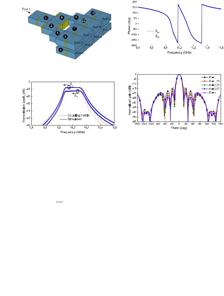
Fig. 9. Simulated phase relationship of the eight-way power divider under
d6 = d9 = 8.63 mm and d7 = d8 = 10.23 mm (K = 3.03). Note that the
two curves are on the top of each other.
Fig. 7. Structure of the equivalent eight-way nonuniform filtering power divider.
Fig. 8. Simulated transmission coefficients of the eight-way power divider (solid lines) and calculated transmission coefficients from the coupling matrix (dashed lines) under d6 = d9 = 8.63 mm and d7 = d8 = 10.23 mm.
output ports. The dimensions of the power divider are kept the same as the dimensions of the nonuniform array listed in Table I. Given d6 = d9 = 8.63 mm and d7 = d8 = 10.23 mm, the simulated and calculated transmission coefficients of the power divider at port 2 and port 3 are depicted in Fig. 8.
In a multiport network, the relationship between |Sm1| and
input–output power can be defined as |
|
|
|
Pi |
(d B) = 20 log10 |
|Sm1| |
|
−10 log10 Pom |
(14) |
||
where Pi is the port m, and |Sm1 value between the we obtain
input power, Pom is the output power at | is the transmission coefficients in linear output port m and the input port. Using (14),
Po3 |
= |
|S31 |
|2 |
. |
(15) |
|
Po2 |
|S21 |
|2 |
||||
|
|
Note that the simulated magnitude of S31 and S21 at the center frequency of 10 GHz is −7.34 and −12.16 dB, respectively. This two decibel values can be transform to linear values as 0.4295 and 0.2466. Hence, the ratio K of nonuniform excitation approximately equals to the output power ratio between port 3 and port 2, which is 0.42952/0.24662 = 3.03. This demonstrates that the coupling coefficient is correctly calculated.
Fig. 10. H -plane radiation patterns of the eight-element filtering antenna array under different excitation power ratio K . (d6 = d9 = 9.25 mm and
d7 = d8 = 9.61 mm for K = 1, d6 = d9 = 9.02 mm and d7 = d8 = 9.84 mm for K = 1.55, d6 = d9 = 9.25 mm and d7 = d8 = 9.61 mm for K = 2.25, d6 = d9 = 8.82 mm and d7 = d8 = 10.04 mm for K = 2.25, d6 = d9 = 8.63 mm and d7 = d8 = 10.23 mm for K = 3.03, and d6 = d9 = 8.48 mm and d7 = d8 = 10.38 mm for K = 4).
Fig. 9 shows the phase responses of the equivalent unequal power divider obtained from CST simulations. The result turns out that there is an in-phase performance of the last-stage resonators. Fig. 10 illustrates the simulated H -plane radiation patterns of the array under different excitation power ratio K . When K increases, the first two sidelobes decrease while the third sidelobe slightly increases. The simulated sidelobe level is lower than −19.7 dB. The results show that K = 3.03 is the best power ratio to feed the nonuniform array in order to reduce sidelode levels.
Fig. 11 presents the simulated E -field magnitude distribution of the proposed nonuniformly fed filtering antenna array. The normalized E -field strength of the middle resonators is larger than that of the side resonators. The simulated and calculated reflection responses of the antenna array are depicted in Fig. 12. The dashed line denotes the calculated result from coupling matrix, and the solid line denotes the simulated result. They are in good agreement.
V. MEASUREMENT RESULTS
The eight-element nonuniformly fed antenna array with optimized parameters presented in Table I is fabricated using aluminum with silver plating on the surface. The distances

This article has been accepted for inclusion in a future issue of this journal. Content is final as presented, with the exception of pagination.
6 |
IEEE TRANSACTIONS ON MICROWAVE THEORY AND TECHNIQUES |
|||
|
|
|
|
|
|
|
|
|
|
|
|
|
|
|
Fig. 11. Simulated E -field magnitude distribution of the eight-element nonuniformly fed array under K = 3.03.
Fig. 12. Simulated and calculated reflection coefficients of the proposed nonuniformly fed array.
Fig. 14. Reflection coefficients and realized gain of the X-band nonuniformly fed filtering antenna array.
Fig. 15. Normalized radiation patterns of the filtering antenna array at 10 GHz. (a) H -plane (xz plane). (b) E -plane (yz plane).
Fig. 13. Photograph of the proposed X-band nonuniformly fed eight-element filtering antenna array.
between the radiation apertures are 0.83λ0 in H -plane and 0.5λ0 in E -plane, respectively. (λ0 is the wavelength of the center frequency in free space.) A photograph of it is shown
in Fig. 13. Metal screws in top cover are used to assemble the component, and there are no tuning screws. The S-parameters are measured using an HP N5230A network analyzer. Fig. 14 shows the simulated and measured reflection coefficients and the broadside array gain. It can be seen that a good filtering characteristic is achieved. The measured center frequency is located close to 10 GHz and return loss is better than 16.63 dB in the passband. The filtering antenna array obtains a measured realized gain of more than 15.58 dBi. The gain is flat in the

This article has been accepted for inclusion in a future issue of this journal. Content is final as presented, with the exception of pagination.
CHEN et al.: X-BAND WAVEGUIDE FILTERING ANTENNA ARRAY
Fig. 16. Simulated and measured radiation efficiencies of the nonuniformly fed filtering antenna array.
TABLE II
SUMMARY OF THE FILTERING ANTENNA ARRAY PERFORMANCE
passband but degrades sharply to below −10 dB when the frequency offsets by 2.5% from 10 GHz. Fig. 15 presents the normalized co-polarization and cross-polarization radiation patterns in H - and E -plane orientations. The simulated and measured sidelobe levels in the H -plane of nonuniform array are below −19.7 and −18.3 dB, respectively. For a uniform array, this would be limited to −13.5 dB. This result shows that the sidelobe is reduced by feeding the antenna array with nonuniform power distribution. The simulated and measured radiation efficiencies are depicted in Fig. 16. The antenna array obtains a measured radiation efficiency of more than 90% from 9.91 to 10.1 GHz. Both the radiation gain and efficiency perform a high selectivity and a pretty out-of-band rejection. The performance of the proposed filtering antenna array operating at 10 GHz is summarized in Table II.
VI. CONCLUSION
This paper has presented an X-band waveguide eightelement filtering antenna array. The array is fed by nonuniform amplitude distribution, which is close to the N = 4 Dolph–Chebyshev distribution. The filtering function is a fourth-order standard Chebyshev equal-ripple response. The coupling matrix has been used to guide the design of the filtering antenna array, and the response results from theoretical calculation are compared with the simulated results. For experimental verification, the array is fabricated and measured. A good agreement between the calculated, simulated, and measured results is achieved. The measured sidelobe levels are lower than −18.3 dB of H -plane and −21.1 dB of E -plane. The gain and efficiency are, respectively, higher than 15.58 dBi and 90% over the passband.
7
REFERENCES
[1]Y. Yusuf and X. Gong, “Compact low-loss integration of high-Q 3-D filters withhighly efficient antennas,” IEEE Trans. Microw. Theory Techn., vol. 59, no. 4, pp. 857–865, Apr. 2011.
[2]H. Chu, J. X. Chen, S. Luo, and Y. X. Guo, “A millimeter-wave filtering monopulse antenna array based on substrate integrated waveguide technology,” IEEE Trans. Antennas Propag., vol. 64, no. 1, pp. 316–321, Jan. 2016.
[3]Y. Zhang, X. Y. Zhang, L. H. Ye, and Y. M. Pan, “Dual-band base station array using filtering antenna elements for mutual coupling suppression,” IEEE Trans. Antennas Propag., vol. 64, no. 8,
pp.3423–3430, Aug. 2016.
[4]C. X. Maoet et al., “Dual-band patch antenna with filtering performance and harmonic suppression,” IEEE Trans. Antennas Propag., vol. 64, no. 9, pp. 4074–4077, Sep. 2016.
[5]J. Zuo, X. Chen, G. Han, L. Li, and W. Zhang, “An integrated approach to RF antenna-filter co-design,” IEEE Antennas Wireless Propag. Lett., vol. 8, pp. 141–144, Sep. 2009.
[6]X. Chen, F. Zhao, L. Yan, and W. Zhang, “A compact filtering antenna with flat gain response within the passband,” IEEE Antennas Wireless Propag. Lett., vol. 12, pp. 857–860, Apr. 2013.
[7]C.-K. Lin and S.-J. Chung, “A compact filtering microstrip antenna with quasi-elliptic broadside antenna gain response,” IEEE Antennas Wireless Propag. Lett., vol. 10, pp. 381–384, Apr. 2011.
[8]C.-K. Lin and S.-J. Chung, “A filtering microstrip antenna array,”
IEEE Trans. Microw. Theory Techn., vol. 59, no. 11, pp. 2856–2863, Nov. 2011.
[9]W.-J. Wu, Y.-Z. Yin, Z.-Y. Zhang, and J.-J. Xie, “A new compact filterantenna for modern wireless communication systems,” IEEE Antennas Wireless Propag. Lett., vol. 10, pp. 1131–1134, Oct. 2011.
[10]M. Troubat et al., “Mutual synthesis of combined microwave circuits applied to the design of a filter-antenna subsystem,” IEEE Trans. Microw. Theory Techn., vol. 55, no. 6, pp. 1182–1189, Jun. 2007.
[11]G. Goussetis and D. Budimir, “Antenna filter for modern wireless systems,” in Proc. 32nd Eur. Microw. Conf., Sep. 2002, pp. 1–3.
[12]Y. Yang and M. Lancaster, “Waveguide slot antenna with integrated filters,” presented at the ESA Workshop Antennas Space Appl., Noordwijk, The Netherlands, Oct. 2010.
[13]T. F. Skaik, M. J. Lancaster, and F. Huang, “Synthesis of multiple output coupled resonator microwave circuits using coupling matrix optimization,” IET Microw. Antennas Propag., vol. 5, no. 9,
pp.1081–1088, Jun. 2011.
[14]X. B. Shang, Y. Wang, W. L. Xia, and M. J. Lancaster, “Novel multiplexer topologies based on all-resonator structures,” IEEE Trans. Microw. Theory Techn., vol. 61, no. 11, pp. 3838–3845, Oct. 2013.
[15]Constantine A. Balanis, Antenna Theory-Analysis and Design, 3rd ed. Hoboken, NJ, USA: Wiley, 2005.
[16]G.-L. Huang, S.-G. Zhou, T.-H. Chio, H.-T. Hui, and T.-S. Yeo, “A low profile and low sidelobe wideband slot antenna array feb by an amplitude-tapering waveguide feed-network,” IEEE Trans. Antennas Propag., vol. 63, no. 1, pp. 419–423, Jan. 2015.
[17]S.-J. Park, D.-H. Shin, and S.-O. Park, “Low side-lobe substrate- integrated-waveguide antenna array using broadband unequal feeding network for millimeter-wave handset device,” IEEE Trans. Antennas Propag., vol. 64, no. 3, pp. 923–932, Mar. 2016.
[18]G.-L. Huang, S.-G. Zhou, T.-H. Chio, C.-Y.-D. Sim, and T.-S. Yeo, “Wideband dual-polarized and dual-monopulse compact array for SAR system integration applications,” IEEE Geosci. Remote Sens. Lett., vol. 13, no. 8, pp. 1203–1207, Aug. 2016.
[19]G.-L. Huang, S.-G. Zhou, and T. H. Chio, “Highly-efficient self-compact
monopulse antenna system |
with integrated comparator network for |
RF industrial applications,” |
IEEE Trans. Ind. Electron., vol. 64, no. 1, |
pp.674–681, Jan. 2017.
[20]G.-L. Huang, S.-G. Zhou, T.-H. Chio, and T.-S. Yeo, “Fabrication of a high-efficiency waveguide antenna array via direct metal laser sintering,”
IEEE Antennas Wireless Propag. Lett., vol. 15, pp. 622–625, Mar. 2016.
[21]G.-L. Huang, S.-G. Zhou, T.-H. Chio, and T.-S. Yeo, “Design of a symmetric rectangular waveguide T-junction with in-phase and unequal power split characteristics,” in Proc. IEEE AP-S Int. Symp., Jul. 2013,
pp.2119–2120.
[22]T. Shem, A. Lehto, and A. V. Räisänen, “Matching of a rectangular waveguide T junction with unequal power division,” Microw. Opt. Technol. Lett., vol. 14, no. 3, pp. 141–143, Feb. 1997.
[23]G. L. Matthaei, L. Young, and E. M. T. Jones, Microwave Filters, Impedance-Matching Networks and Coupling Structures. North Bergen, NJ, USA: Artech House, 1980.

This article has been accepted for inclusion in a future issue of this journal. Content is final as presented, with the exception of pagination.
8
[24]M. J. Lancaster, Passive Microwave Device Applications of HighTemperature Superconductors. Cambridge, U.K.: Cambridge Univ. Press, 1997.
[25]J. S. Hong and M. J. Lancaster, Microstrip Filters for RF/Microwave Applications. New York, NY, USA: Wiley, 2001.
[26]J. D. Kraus and R. J. Marhefka, Antennas: For All Applications, 3rd ed. New York, NY, USA: McGraw-Hill, 2003.
Fu-Chang Chen (M’12) was born in Fuzhou, Jiangxi, China, in 1982. He received the Ph.D. degree from the South China University of Technology, Guangzhou, Guangdong, China, in 2010.
He is currently an Associate Professor with the School of Electronic and Information Engineering, South China University of Technology. His current research interests include the synthesis theory and design of microwave filters and associated RF modules for microwave and millimeter-wave applications.
Jian-Feng Chen was born in 1992. He received the B.S. degree in information engineering from the South China University of Technology, Guangzhou, China, in 2015, where he is currently pursuing the M.E. degree.
His current research interests include microwave antennas and associated RF circuits for microwave applications.
IEEE TRANSACTIONS ON MICROWAVE THEORY AND TECHNIQUES
Qing-Xin Chu (M’99–SM’11) received the B.S., M.E., and Ph.D. degrees in electronic engineering from Xidian University, Xi’an, Shaanxi, China, in 1982, 1987, and 1994, respectively.
From 1982 to 2004, he was with the School of Electronic Engineering, Xidian University, where he has been a Professor and the Vice Dean since 1997, and a Distinguished Professor of the Shaanxi Hundred-Talent Program since 2011. He is currently a Chair Professor with the School of Electronic and Information Engineering, South China University
of Technology, Guangzhou, China, where he is also the Director of the Research Institute of Antennas and RF Techniques and the Chair of the Engineering Center of Antennas and RF Techniques of Guangdong Province. He has authored over 300 papers in journals and conferences, which were indexed in SCI more than 1500 times. One of his papers published in the IEEE TRANSACTIONS ON ANTENNAS AND PROPAGATION in 2008 becomes the top Essential Science Indicators paper within ten years in the field of antenna (SCI indexed self-excluded in the antenna field ranged top 1%). His current research interests include antennas in wireless communication, microwave filters, spatial power combining array, and numerical techniques in electromagnetics.
Dr. Chu is the Foundation Chair of the IEEE Guangzhou AP/MTT Chapter and a Senior Member of the China Electronic Institute. He was the recipient of the Science Award of Guangdong Province in 2013, the Science Award of the Education Ministry of China in 2008 and 2002, the Fellowship Award of the Japan Society for Promotion of Science in 2004, the Singapore Tan Chin Tuan Exchange Fellowship Award in 2003, and the Educational Award by Shaanxi Province in 2003.
Michael J. Lancaster (SM’04) was born in Keighley, U.K., in 1958. He received the B.Sc. degree in physics and Ph.D. degree in nonlinear underwater acoustics from Bath University, Bath, U.K., in 1980 and 1984, respectively.
He joined the Surface Acoustic Wave Group,
Department |
of Engineering |
Science, University |
of Oxford, |
Oxford, U.K., as |
a Research Fellow. |
In 1987, he joined the Department of Electronic and Electrical Engineering, University of Birmingham, Birmingham, Edgsbaston, U.K., as a Lecturer of
electromagnetic theory and microwave engineering, where he began the study of the science and applications of high-temperature superconductors in which he was involved in research on microwave frequencies. He became the Head of the Emerging Device Technology Research Centre in 2000 and the Head of the Department of Electronic, Electrical and Computer Engineering in 2003 with the University of Birmingham. He has authored 2 books and over 190 papers in refereed journals. His current research interests include microwave filters and antennas and the high-frequency properties and applications of a number of novel and diverse materials.
Prof. Lancaster is a Fellow of the IET and the Institute of Physics in the U.K. He is a Chartered Engineer and a Chartered Physicist. He has served on the IEEE MTT-S IMS Technical Committee.