

диафрагмированные волноводные фильтры / 6c4c3877-e8a3-4dcc-8259-95645394a06d
.pdf584 |
IEEE TRANSACTIONS ON MICROWAVE THEORY AND TECHNIQUES, VOL. 59, NO. 3, MARCH 2011 |
A Laminated Waveguide Magic-T With Bandpass
Filter Response in Multilayer LTCC
Tze-Min Shen, Student Member, IEEE, Ting-Yi Huang, Member, IEEE,
Chi-Feng Chen, and Ruey-Beei Wu, Fellow, IEEE
Abstract—A laminated waveguide magic-T with imbedded Chebyshev filter response is developed in a multilayer low-temper- ature co-fired ceramic technology by vertically stacked rectangular cavity resonators with highly symmetric coupling structures. The cavities provide evenand odd-symmetric field distributions by simultaneously resonating and modes at the center frequency of the magic-T. Thus, the in-phase and out-of-phase responses of the magic-T function are accomplished according to the induced mode. Meanwhile, the filter frequency response is realized by the cascaded cavities with proper coupling strengths according to the filter specification. With the degenerate, but orthogonal cavity modes, a fewer number of cavities are required and the circuit size is further reduced. A third-order bandpass magic-T is designed and fabricated to operate at 24 GHz with 6% fractional bandwidth. The highly symmetric structure of the implemented magic-T provides a low in-band magnitude imbalance ( 0.25 dB) and phase imbalance (0
 –6
–6 ). The sum and difference ports also provide an isolation greater than 30 dB in the operation frequency range. Measurement and simulated results are in good agreement, both validating the design concept.
Index Terms—Ceramic, filter, laminated waveguide, magic-T.
I. INTRODUCTION
WITH THE rapid growth of wireless technologies, there is an ever increasing need for low-cost, high-perfor- mance, and high-integration RF front-end modules. Filters and 180 hybrids are two important passive components in the front-end module of many radar and sensor applications, such as a monopulse tracking radar [1]. They are usually arranged in a cascade fashion between the antenna and receive integrated circuit (IC). Therefore, integration of both functionalities into a single device will be beneficial to reduce the interconnection
loss, circuit area, and manufacturing cost.
Several couplers inherent with bandpass responses are proposed. The quarter-wavelength transmission-line section in a conventional rat-race and branch-line coupler is transformed into an analogy of coupled-resonator network at the center frequency [2]–[4]. Thus, the realized coupler can demonstrate
Manuscript received July 04, 2010; revised December 14, 2010; accepted December 21, 2010. Date of publication February 10, 2011; date of current version March 16, 2011. This work was jointly supported by the National Science Council under Grant NSC96-2219-E-002-017 and the Excellent Research Project of National Taiwan University under Grant 98R0062-03.
The authors are with the Department of Electrical Engineering and Graduate Institute of Communication Engineering, National Taiwan University, Taipei 10617, Taiwan (e-mail: r93942015@ntu.edu.tw; rbwu@ew.ee.ntu.edu.tw).
Color versions of one or more of the figures in this paper are available online at http://ieeexplore.ieee.org.
Digital Object Identifier 10.1109/TMTT.2011.2104973
filter characteristics, but with primitive bandpass response since it is not capable of increasing the filter order for better selectivity. Symmetrical four-port networks are developed to realize balance-to-unbalanced (baluns) by applying specific boundary conditions [5], [6]. The bandpass response is achieved by cascading multisection baluns. However, the filter response may not be designed. Recently, the balun filters with specific bandpass characteristics are well developed [7]–[10]. Several compact resonators are also proposed to miniaturize the circuit sizes [11], [12]. In [13], the balun filter is further incorporated with a single-to-common filter to form a bandpass 180 hybrid. However, since the balun filter and single-to-common filter are designed and realized separately, the hybrid needs more resonators.
On the other hand, the laminated waveguide [14], or equivalently, substrate integrated waveguide (SIW) [15] devices have become popular in recent years. The waveguide is embedded in a dielectric substrate with metal layers as the outer surfaces and via arrays as vertical sidewalls. It can be synthesized by using the printed circuit board (PCB) processes or low-temperature co-fired ceramic (LTCC) technologies. The dielectric substrate is also used for other devices and serves as the package for integrated circuits [16]. The entire system is then able to integrate into a single package, i.e., system-on-package (SoP).
SIW filters [17]–[20] and couplers [21], [22] have recently attracted the attention of researchers’, having not only the advantages of traditional waveguide components, such as high quality factor and low loss, but also easy integration with planar circuits. The multimode property of the waveguide cavity is also utilized to realize the filters with special features, e.g., dual-band responses [23], tri-band with highly flexible band allocation [24], and wide stopband performance [25]. Recently, several planar magic-Ts are developed with SIW structures as well. The circuits are formed by cascading a T-shaped slot and a SIW T-junction [26] or by stacked waveguide structures on double-layer PCBs [27], [28]. In these studies, additional tuning posts are needed to improve the impedance matching and the SIW T-junctions occupy a large circuit area. Later, an
 -plane SIW power divider [29] or a modified SIW T-junction [30] along with a slot-to-SIW transition is proposed to improve the operation bandwidth and reduce circuit sizes. Another magic-T design based on orthogonal slots excitation is proposed to provide a broad out-of-phase combining bandwidth [31]. The above magic-T designs are accomplished by exciting the fundamental


 mode of the main guide and achieving impedance matching at a specific frequency. It is incapable of controling the precise operation bandwidth and the out-band
0018-9480/$26.00 © 2011 IEEE

SHEN et al.: LAMINATED WAVEGUIDE MAGIC-T WITH BANDPASS FILTER RESPONSE IN MULTILAYER LTCC |
585 |
selectivity. Therefore, a bandpass filter is often used next to the magic-T in the front-end module. In [32], a band-rejection filter realized by a waveguide magic-T structure is proposed. Although a magic-T structure is used, the topology only provides the bandstop frequency response. The magic-T functions are not preserved. Therefore, the joint function with a filter and a coupler characteristic in a single laminated waveguide component has not been presented.
In this paper, a laminated waveguide magic-T, one kind of 180 hybrid, with a multiorder Chebyshev filter response is developed in the multilayer LTCC technology by cascaded cavities with


 and
and 


 modes resonating at the common center frequency. It is organized as follows. Section II describes the design concept to achieve the magic-T function and tailor the coupling coefficients for the desired Chebyshev filter. Section III manifests the proposed structure and the step-by-step design procedure for an exemplified magic-T with third-order bandpass filter performance. The filter is fabricated and measured results are compared with the simulation data in Section IV, followed by brief conclusions in Section V.
II. DESIGN CONCEPT
A. Magic-T Design
Fig. 1(a) shows the geometry of a rectangular cavity, where 
 and
and  are the cavity’s width, height, and length, respectively. The resonant frequency of the


 or
or 


 mode is decided by [33]
(1)
where 
 and
and 
 are relative permeability and relative permittivity of the cavity substrate,
  is speed of light, and integers
 and
and  are mode indices of the resonator. It is worth noting that every resonant mode exhibits evenor odd-symmetric field patterns. This structural symmetry is pivotal to realize an exact inor out-of-phase response.
In this study, two degenerate modes, 


 and
and 


 , are utilized to achieve a magic-T function in a single cavity. The dimensions of the cavity with degenerate


 and
and 


 modes can be determined by (1). The corresponding field patterns are plotted in Fig. 1(b) and (c), which show the oddand even-symmetric electric field distributions, respectively, in the
  -direction. The cavity may be excited by microstrip lines through slots on the outer metal layer [34]. In Fig. 1(b) and (c), two orthogonal slots etched on the cavity are used to induce the


 and
and 


 modes, independently. One slot is placed normal to the circuit symmetric plane and the other is on the plane. When the slot on the symmetric plane is excited, it will induce the magnetic current in the direction of the slot and result in the


 mode, as shown in Fig. 1(b). The odd-symmetric electric field pattern can be utilized to achieve the out-of-phase response of a magic-T. On the other hand, the slot normal to the symmetric plane induces the


 mode, as shown in Fig. 1(c). The even-symmetric electric field pattern can realize the in-phase response of a magic-T. Since both modes are designed to resonate at the same frequency,
Fig. 1. (a) Geometry of a rectangular cavity resonator. Electric and magnetic field patterns of a resonant cavity in: (b) 

 mode and (c)

 mode.
mode.
(d) Four-port magic-T configuration.
the cavity is able to provide inand out-of-phase responses simultaneously, which is required in the magic-T implementation. Moreover, the magnetic fields caused by one slot will cancel out at the other, resulting in a good isolation. Due to the structural symmetry, the phase and the isolation property are excellently satisfied, independent of the frequency. It should be mentioned that the aforementioned magic-T design concept may be applied to the cavity with other degenerate modes that have opposite symmetry property.
Next, the scattering parameters analysis of the magic-T with the dual-behavior cavity, which simultaneously provides inand out-of-phase responses, can follow the procedure in [35]. For the four ports magic-T network, as shown in Fig. 1(d), assume that port 1 excites the slot on the symmetric plane of the cavity, and the slot normal to the plane is excited by port 4. Ports 2 and 3 are two output ports, which symmetrically extract fields from the magic-T. Due to the perfect isolation between the orthogonal slots, 

 equals zero. The rest of the elements of the matrix can be simplified by the properties of reciprocity and even and odd symmetry of the cavity. The corresponding scattering matrix can be expressed in the form

586 |
IEEE TRANSACTIONS ON MICROWAVE THEORY AND TECHNIQUES, VOL. 59, NO. 3, MARCH 2011 |
Fig. 2. (a) Traditional realization of cascading the magic-T function and the filter function. (b) Proposed general coupling structure of a magic-T with a specific filter response.
(2)
The orthogonal slots should be suitably designed so that ports 1 and 4 are nearly matched at the frequency band of interest. According to the unitary property of a lossless network, 

 and
and 
 will then be close to

 and the other output ports are guaranteed good matching and high isolation. The deduced scattering parameters are described as follows:
(3)
where 


 and
and  are small values. Therefore, the
  -ma- trix in (3) can represent the general form of the magic-T circuit. The design of a waveguide magic-T with the presented dual-be- havior cavity can be simplified to the impedance match design at orthogonal feeding slots, i.e., to keep
 and
and 
 small over a specific frequency range. In Section II-B, the impedance match design will be described and accomplished together with the filter design.
B. Filter Design
Fig. 2(a) shows the traditional realization of the 180 hybrid combined with the filter function by cascading a magic-T with two bandpass filters. The nodes represent the resonators of the filters. In this study, a general coupling structure of the bandpass magic-T with a specific filter response is proposed, as shown in Fig. 2(b). Each node represents a cavity with degenerate


 and
and 


 modes and the lines indicate the coupling between the cavities. The superscripts, I and II, denote


 and
and 


 modes of the cavity, respectively. Both modes resonate at the center frequency of the magic-T. Compared with the traditional realization in Fig. 2(a), the proposed topology can save the implementation of the magic-T and one bandpass filter, which contributes to the size reduction and the manufacture simplicity.
In Fig. 2(b), the input cavity is excited by the aforementioned orthogonal slots. Only one of the 


 and
and 


 modes will be excited according to the feeding slot. The internal coupling structures should maintain the structural symmetry to keep the modal orthogonality in the following cavities. Therefore, the
in-phase and out-of-phase transmission responses are achieved by 


 and
and 


 modes, separately. The output cavity is coupled by two symmetric feeding structures. The output signals are then equally divided and result in the required phase responses according to the excited cavity mode. Therefore, in the proposed bandpass magic-T topology,


 and
and 


 modes are separately excited to synthesize filter responses. Both modes are realized in the same cavity, thus two filter responses for in-phase and out-of-phase operations can be simultaneously achieved by a single filter structure.
The design parameters of bandpass filters, i.e., the coupling coefficients and external quality factors in Fig. 2(b), can be determined in terms of the circuit elements of a low-pass prototype filter [33]. The relationship between coupling coefficients and physical structures of coupled resonators should be established in order to determine the physical dimension of the filter against the design parameters. The coupling coefficient can be specified by two split resonant frequencies [36], i.e.,
(4)
Here, 
 and
and 
 are defined to be the lower and higher resonant frequencies, respectively. The external quality factor can be characterized by [36]
(5)
in which  denotes the center frequency, and


 indicates the
  90
90 bandwidth of the resonator. The filter functions achieved by


 and
and 


 modes should have an identical coupling matrix. Thus, it can maintain the same bandpass response and bandwidth in both in-phase and out-of-phase operations.
When dimensions of the coupling structures are carefully chosen to satisfy the corresponding coupling matrix, the filter function is achieved, which means the impedance matching at the input feeding slots is naturally fulfilled in the passband. Therefore, according to the deduced scattering parameters in (3), the magic-T function is also accomplished in the passband.
III. MAGIC-T WITH CHEBYSHEV FILTER RESPONSE
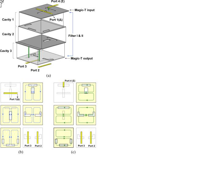
Without loss of generality, a laminated waveguide magic-T with a third-order Chebyshev filter response is chosen as the example to demonstrate the proposed idea. Fig. 3(a) sketches the highly symmetric circuit configuration, which is composed of three rectangular cavities stacked vertically in the multilayer LTCC. The shorting vias to enclose the cavities are neglected and the dimensions in the vertical direction are enlarged for clarity. The orthogonal slots etched at the top cavity serve as the inputs of the magic-T, which excite even and odd symmetric field patterns, respectively. The outputs of the magic-T are realized by the symmetric L-shaped slots etched at the bottom cavity. All the cavities are designed to resonate both 


 and
and 


 modes at the center frequency of the magic-T. The bandpass filter responses of the inand out-of-phase signals are achieved by


 and
and 


 modes, respectively. Thus, only three physical cavities are needed to realize both the third-order filter responses in the inand out-of-phase operation. The six
SHEN et al.: LAMINATED WAVEGUIDE MAGIC-T WITH BANDPASS FILTER RESPONSE IN MULTILAYER LTCC |
587 |
Fig. 3. (a) 3-D view of a laminated waveguide magic-T with third-order Chybeshev filter response. Magnetic field patterns at each layer of the filter for:
(b) out-of-phase and (c) in-phase operation.
metal layers are tiled and shown in Fig. 3(b) and (c) with the corresponding operation modes. The field patterns show that, except for the input orthogonal slots, the inand out-of-phase signal paths share the common internal coupling slots and the L-shaped output slots.
It is worth noting the presence of two additional shorting vias in the bottom cavity of Fig. 3(a). They are used to offset the higher order resonant modes to higher frequencies. By staggering the higher order resonant frequencies of the cavities, the spurious response of the magic-T can be improved [37].
The cavities are fed by microstrip lines through the slots etched on the outer metal layers. The internal couplings are achieved by the slots on the common broad wall between the adjacent cavities. The slots are located close to the maximum magnetic fields of the cavities, with their directions perpendicular to the surface currents on the metal layers. Hence, the slot discontinuities will significantly interrupt the surface current flows and introduce strong magnetic couplings, analogous to the design principle of waveguide slot antenna [38]. The shorting via or quarter-wavelength open stubs are connected to the feed lines to maximize the magnetic couplings [34].
Besides, the slot locations at two neighbor broad walls should be chosen to avoid overlap, which may prevent additional cross couplings between nonadjacent cavities.
This waveguide magic-T is fabricated in LTCC technology on the substrate with relative dielectric constant 3.9 and loss tangent 0.006. The fabrication process provides ten dielectric layers and the metal patterns on the layers are formed by 10- m-thick silver. The feeding microstrip lines utilize the first two and the last dielectric layers. The substrate thicknesses are 115 and 100
  m. Cavity 1, with 200-
 m thickness, occupies from layer 3 to layer 5. Cavities 2 and 3 with 300and 200-
 m thickness utilize layers 6–7 and layers 8–9, respectively.
Assume that the filter has specifications of central frequency at 24 GHz and fractional bandwidth of 6%. For the present design, the first step is to decide the dimensions of the cavities. To resonate 


 and
and 


 modes at the above frequency, the sizes of unloaded cavity 1 are calculated by (1) with


 m, where

 and
and 

 denote the unloaded cavity width and length, respectively. Cavity 2 has the same sizes as cavity 1, However, the cavity width


 m and length


 m are chosen as the dimensions of the unloaded cavity 3. The sizes are different from other cavities due to the existence of two additional shorting vias.
The second step is to calculate the coupling coefficients and external quality factor to meet the filter specification. They can be acquired based on low-pass prototype values of the thirdorder Chebyshev frequency response with a 0.1-dB ripple level. The element values are 


and 


 . For the 6% fractional bandwidth, the corresponding coupling coefficients and I/O external quality factor can then be found as [36]
(6)
Note that the bandpass magic-T under 


 - and
- and 


 -mode operation should use the same coupling matrix to maintain the same bandwidth and frequency response.
The third step is to realize the coupling coefficients and external quality factor by suitably choosing the lengths, locations, and shapes of the coupling slots. For the external quality factor extraction, the input cavity excited by microstrip lines through two orthogonal slots is shown in Fig. 4(a). The slot widths are 200  m. The external quality factors are controlled by the lengths of the slots and calculated directly by (5). Fig. 4(b) plots the relation of external quality factors versus the slot lengths

 and
and 

 , which are normalized to the unloaded cavity width

 .
.
Besides, the width and length of the cavity should be adjusted to compensate for the shifted resonant frequency due to the presence of the slots [17]. 

 is the difference between the modified cavity width
 and the original cavity width

 .
. 

 denotes the variation in the cavity length. The relation between external quality factors and the variation of cavity dimensions are also plotted in Fig. 4(b). The adjustments in the cavity width and length are normalized to the unloaded cavity width and length, respectively. In this magic-T design, for example,

588 |
IEEE TRANSACTIONS ON MICROWAVE THEORY AND TECHNIQUES, VOL. 59, NO. 3, MARCH 2011 |
Fig. 5. (a) 3-D view and (b) top view of the output cavity fed by two L-shaped slots. (c) External quality factor with  m.
m.
Fig. 4. (a) Input cavity fed by microstrip lines. (b) External quality factor with
 m.
m.
the external quality factor of 17.2 is needed. To meet the requirement, one can choose the slot lengths with 


 and
and 


 . In the meantime, to keep the resonant frequency invariant, the cavity width and length should be slightly decreased with


 and
and 


 as the initial dimensions of cavity 1.
The output cavity is coupled by bottom microstrip lines through a pair of symmetric L-shaped slots, as shown in Fig. 5(a) and (b). The L-shape is chosen so that the slot can extract the signals from both the 


 and
and 


 modes in the cavity. Due to the symmetric arrangement of the two slots, the output signals are assured to be equally divided with out-of-phase and in-phase responses, respectively.
Since 


 and
and 


 modes will be excited by the L-shaped slots simultaneously, the external quality factor should be extracted by the evenand odd-mode analysis to avoid the mutual coupling between two resonant modes. The odd-mode condition represents the


 mode operation, while the even-mode condition denotes the


 mode operation. Both the evenand odd-mode conditions should achieve the same external quality factor according to the design specification. Fig. 5(c) shows the external quality factor versus the slot dimensions and the variation of the cavity sizes. The slot widths are 200
  m and the distance between the slots and the cavity sidewalls are 150
  m. It can be seen that the smaller the external quality factor, the larger the coupling slot length and the cavity size variation.
For the coupling coefficient extraction, the coupling between cavity 1 and cavity 2 is achieved by the slots on the common
Fig. 6. (a) Structure for extracting 
 and (b) associated design curve for

 .
.
broad wall, as shown in Fig. 6(a). The lengths and locations of the slots are selected to achieve the same coupling strength under both 


 and
and 


 mode operations. The evenand odd-mode conditions are also adapted to calculate the coupling

SHEN et al.: LAMINATED WAVEGUIDE MAGIC-T WITH BANDPASS FILTER RESPONSE IN MULTILAYER LTCC |
589 |
Fig. 7. (a) 3-D view and (b) top view of the structure for extracting 
 and
and
(c) associated design curve for 
 with
with  m,
m,  m, and
  m.
m.
Fig. 9. Measured and simulated frequency responses of the waveguide magic-T at: (a) port 1 and (b) port 4. (c) Isolation 
 between sum and difference ports.
strength. The coupling coefficients versus the slot lengths and the cavity variations are plotted in Fig. 7(c). The dimension variations of cavity 3 are different from that of cavity 2 due to the presence of two additional shorting vias.
IV. EXPERIMENTAL VERIFICATION
Fig. 8. (a) Whole structure of a bandpass waveguide magic-T with vertical transition. (b) Fabricated waveguide magic-T.
coefficient by (4). The coupling coefficients versus the slot lengths and the cavity size variations are plotted in Fig. 6(b). The slot widths are 200  m and the distance between the slots and the cavity sidewalls are 150
  m.
m.
In Fig. 7(a) and (b), the slots between cavity 2 and cavity 3 show another coupling structure to achieve the desired coupling
The proposed laminated waveguide magic-T with third-order Chebyshev filter response is designed and fabricated in the multilayer LTCC technology. To allow on-wafer measurement by coplanar probes, the input and output microstrip lines should be on the same layer. Therefore, two vertical transitions composed of through-hole vias are used to connect the bottom microstrip lines to the top layer. Eight grounded vias are located around the through-hole vias to mimic a coaxial transmission line effect. Fig. 8(a) shows the overall magic-T configuration

590 |
IEEE TRANSACTIONS ON MICROWAVE THEORY AND TECHNIQUES, VOL. 59, NO. 3, MARCH 2011 |
V. CONCLUSION
Fig. 10. Measured frequency responses of: (a) magnitude imbalance and
(b) phase imbalance.
and Fig. 8(b) is a photograph of the fabricated magic-T. The whole size of the waveguide magic-T without the vertical transition is 7.5  7.95
7.95  0.93 mm
 , i.e.,


 , where
  is the wavelength in the dielectric substrate. Other geometric parameters are


 m,
m, 


 m,
m, 


 m,
m, 


 m,
m, 


 m,
m, 


 m,
m, 


 m,
m, 


 m,
m, 


 m,
m, 


 m,
m, 


 m,
m, 


 m,
m, 


 m,
m, 


 m, and


 m.
m.
The magic-T with two vertical transitions included is measured on an Agilent E8361A network analyzer. The circuit performance is characterized through on-wafer coplanar ground–signal–ground (GSG) probes. Two magic-T ports are measured at a time, while the other ports are terminated with 50- broadband precision load. The measurement results are shown in Fig. 9(a)–(c). The center frequencies are 24.1 and 24.25 GHz in port 1 and port 4, respectively. The 3-dB bandwidth of port 1 is 2.07 GHz ranging from 23.07 to 25.14 GHz. The bandwidth of port 4 is 2.09 GHz ranging from 23.2 to 25.29 GHz. Within the passband, the minimum insertion loss is 5.24 and 5.2 dB in port 1 and port 4, where the magic-T provides an intrinsic 3-dB insertion loss. The isolation between port 1 and port 4 are better than 30.7 dB.
The measured in-band magnitudeand phase-imbalances between port 2 and port 3 are also shown in Fig. 10(a) and (b). The corresponding amplitude imbalance is less than  0.25 dB, and the corresponding phase imbalance is between 0
 –6
–6 .
.
In this study, a laminated waveguide magic-T with a specific filter response has been presented. The filter and magic-T functions are combined in a single SIW component. It adopts the degenerate, but orthogonal cavity modes to realize both in-phase and out-of-phase filter responses in one physic filter structure. Two orthogonal slots are located on the symmetric plane to independently excite 


 and
and 


 modes of the cavity and result in an in-phase and out-of-phase responses, respectively. The filter response is then accomplished by proper couplings between the cascaded cavities according to the filter specification. Compared with the traditional realization of both magic-T and filter functions, it can save the implementation of a magic-T and one filter, which contributes to circuit miniaturization and simplicity. Besides, with the multilayer capability of LTCC technology, the cavities are piled up in 3-D space, which will largely reduce the circuit area and increase the design flexibility.
The working mechanism and theory of the magic-T has been described. The design of the magic-T is deduced to simply achieve impedance matching at sum and difference ports. The concept of the dual-behavior cavity guarantees in-phase and out-of- phase responses, thus fewer cavities are needed in the magic-T implementation. The design procedure of the filter is described. It can be easily applied to other Chebyshev filters with various bandwidth and higher order responses. An exemplified bandpass magic-T with a third-order Chebyshev response at a center frequency of 24 GHz and 6% bandwidth is designed and validated in LTCC technology. The fabricated magic-T shows a low magnitude imbalance ( 0.25 dB), phase imbalance (0
 –6
–6 ), and good isolation (30 dB) in the desired frequency range.
REFERENCES
[1]K. Chang, RF and Microwave Wireless Systems. New York: Wiley, 2000, ch. 7.
[2]H. Uchida, N. Yoneda, Y. Konishi, and S. Makino, “Bandpass directional couplers with electromagnetically-coupled resonators,” in IEEE MTT-S Int. Microw. Symp. Dig., 2006, pp. 1563–1566.
[3]W.-H. Wang, T.-M. Shen, T.-Y. Huang, and R.-B. Wu, “Miniaturized rat-race coupler with bandpass response and good stopband rejection,” in IEEE MTT-S Int. Microw. Symp. Dig., 2009, pp. 709–712.
[4]W.-L. Chang, T.-Y. Huang, T.-M. Shen, B.-C. Chen, and R.-B. Wu, “Design of compact branch-line coupler with coupled resonators,” in Asia–Pacific Microw. Conf., Bangkok, Thailand, Dec. 2007, pp. 1375–1378.
[5]Y. C. Leong, K. S. Ang, and C. H. Lee, “A derivation of a class of 3-port baluns from symmetrical 4-port networks,” in IEEE MTT-S Int. Microw. Symp. Dig., 2002, pp. 1165–1168.
[6]K. S. Ang, Y. C. Leong, and C. H. Lee, “Analysis and design of miniaturized lumped-distributed impedance-transforming baluns,”
IEEE Trans. Microw. Theory Tech., vol. 51, no. 3, pp. 1009–1017, Mar. 2003.
[7]L. K. Yeung and K. L. Wu, “An LTCC balanced-to-unbalanced ex- tracted-pole bandpass filter with complex load,” IEEE Trans. Microw. Theory Tech., vol. 54, no. 4, pp. 1512–1518, Apr. 2006.
[8]K. T. Chen and S. J. Chung, “A novel compact balanced-to-unbalanced low-temperature co-fired ceramic bandpass filter with three coupled lines configuration,” IEEE Trans. Microw. Theory Tech., vol. 56, no. 7, pp. 1714–1720, Jul. 2008.
[9]C.-H. Wu and C.-H. Chen, “Balanced-to-unbalanced bandpass filters and the antenna application,” IEEE Trans. Microw. Theory Tech., vol. 56, no. 11, pp. 2474–2482, Nov. 2008.
[10]C.-L. Tsai and Y.-S. Lin, “Analysis and design of new single-to-bal- anced multi-coupled line bandpass filters using low-temperature co-fired ceramic technology,” IEEE Trans. Microw. Theory Tech., vol. 56, no. 12, pp. 2902–2912, Dec. 2008.

SHEN et al.: LAMINATED WAVEGUIDE MAGIC-T WITH BANDPASS FILTER RESPONSE IN MULTILAYER LTCC |
591 |
[11]M. Tamura, T. Ishizaki, and M. Hoft, “Design and analysis of vertical split ring resonator and its application to unbalanced-balanced fitler,”
IEEE Trans. Microw. Theory Tech., vol. 58, no. 1, pp. 157–164, Jan. 2010.
[12]T. Yang, M. Tumura, and T. Itoh, “Compact hybrid resonator with series and shunt resonances used in miniaturized filters and balun filters,”
IEEE Trans. Microw. Theory Tech., vol. 58, no. 2, pp. 390–402, Feb. 2010.
[13]C.-H. Wu and C.-H. Chen, “Compact LTCC bandpass 180 hybrid using lumped single-to-differential and single-to-common bandpass filters,” in IEEE MTT-S Int. Microw. Symp. Dig., 2009, pp. 709–712.
[14]H. Uchimura, T. Takenoshita, and Fujii, “Development of a laminated waveguide,” IEEE Trans. Microw. Theory Tech., vol. 46, no. 12, pp. 2438–2443, Dec. 1998.
[15]K. Wu, “Integration and interconnect techniques of planar and nonplanar structures for microwave and millimetre-wave circuits—Current status and future trend,” in Asia–Pacific Microw. Conf., Taipei, Taiwan, Dec. 2001, pp. 411–416.
[16]T. Baras and A. F. Jacob, “Manufacturing reliability of LTCC mil- limeter-wave passive components,” IEEE Trans. Microw. Theory Tech., vol. 56, no. 11, pp. 2574–2581, Nov. 2008.
[17]M. Ito, K. Maruhashi, K. Ikuina, T. Hashiguchi, S. Iwanaga, and K. Ohata, “A 60-GHz-band planar dielectric waveguide filter for flip-chip modules,” IEEE Trans. Microw. Theory Tech., vol. 49, no. 12, pp. 2431–2436, Dec. 2001.
[18]J. A. Ruiz-Cruz, M. A. E. Sabbagh, K. A. Zaki, J. M. Rebollar, and Y. Zhang, “Canonical ridge waveguide filters in LTCC or metallic resonators,” IEEE Trans. Microw. Theory Tech., vol. 53, no. 1, pp. 174–182, Jan. 2005.
[19]J.-H. Lee, S. Pinel, J. Papapolymerou, J. Laskar, and M. M. Tentzeris, “Low-loss LTCC cavity filters using system-on-package technology at 60 GHz,” IEEE Trans. Microw. Theory Tech., vol. 53, no. 12, pp. 3817–3824, Dec. 2005.
[20]T.-M. Shen, C.-F. Chen, T.-Y. Huang, and R.-B. Wu, “Design of vertically stacked waveguide filters in LTCC,” IEEE Trans. Microw. Theory Tech., vol. 55, no. 8, pp. 1771–1779, Aug. 2007.
[21]B. Liu, W. Hong, Z. C. Hao, and K. Wu, “Substrate integrated waveguide 180-degree narrow-wall directional coupler,” in Proc. Asia–Pa- cific Microw. Conf., Suzhou, China, Dec. 2005, vol. 1, pp. 559–561.
[22]Z. Y. Zhang and K. Wu, “A broadband substrate integrated waveguide (SIW) planar balun,” IEEE Microw. Wireless Compon. Lett., vol. 17, no. 12, pp. 843–845, Dec. 2007.
[23]B.-J. Chen, T.-M. Shen, and R.-B. Wu, “Dual-band vertically stacked laminated waveguide filter design in LTCC technology,” IEEE Trans. Microw. Theory Tech., vol. 57, no. 6, pp. 1554–1562, Jun. 2009.
[24]W.-L. Tsai and R.-B. Wu, “Tri-band filter design using substrate integrated waveguide resonators in LTCC,” in IEEE MTT-S Int. Microw. Symp. Dig., Anaheim, CA, May 2010, pp. 445–448.
[25]X.-P. Chen, K. Wu, and D. Drolet, “Substrate integrated waveguide filter with improved stopband performance satellite ground terminal,”
IEEE Trans. Microw. Theory Tech., vol. 57, no. 3, pp. 674–683, Mar. 2009.
[26]F. F. He, K. Wu, W. Hong, H. J. Tang, H. B. Zhu, and J. X. Chen, “A planar magic-T using substrate integrated circuits concept,” IEEE Microw. Wireless Compon. Lett., vol. 18, pp. 386–388, Jun. 2008.
[27]M. Liu and F. Feng, “A novel hybrid planar SIW magic tee,” in Proc. Asia–Pacific Microw. Conf., Hong Kong, Dec. 2008, pp. B2–03.
[28]L. Han, K. Wu, and S. Winkler, “Singly balanced mixer using substrate integrated waveguide magic-T structure,” in Proc. Eur. Wireless Technol. Conf., Amsterdam, The Netherlands, Oct. 2008, pp. 9–12.
[29]W. Feng, W. Che, and K. Deng, “Compact planar magic-T using-plane substrate integrated waveguide (SIW) power divider and slotline transition,” IEEE Microw. Wireless Compon. Lett., vol. 20, no. 6, pp. 331–333, Jun. 2010.
[30]F. F. He, K. Wu, X. P. Chen, L. Han, and W. Hong, “A planar magic-T structure using substrate integrated circuits concept,” in IEEE MTT-S Int. Microw. Symp. Dig., Anaheim, CA, May 2010, pp. 720–723.
[31]T.-M. Shen, T.-Y. Huang, and R.-B. Wu, “A laminated waveguide magic-T in multilayer LTCC,” in IEEE MTT-S Int. Microw. Symp. Dig., Jun. 2009, pp. 713–716.
[32]P. A. Rizzi, “Microwave filters utilizing the cutoff effect,” IRE Trans. Microw. Theory Tech., vol. MTT-4, no. 1, pp. 36–40, Jan. 1956.
[33]D. M. Pozar, Microwave Engineering, 2nd ed. New York: Wiley, 1998, ch. 6 and 8.
[34]J.-H. Lee, S. Pinel, J. Papapolymerou, J. Laskar, and M. M. Tentzeris, “Comparative study of feeding techniques for threedimensional cavity resonators at 60 GHz,” IEEE Trans. Adv. Packag., vol. 30, no. 1, pp. 115–123, Feb. 2007.
[35]R. E. Collin, Fundamental for Microwave Engineering, 2nd ed. Piscataway, NJ: IEEE Press, 2001, ch. 6.
[36]J. S. Hong and M. J. Lancaster, Microstrip Filter for RF/Microwave Applications. New York: Wiley, 2001, ch. 5 and 8.
[37]C.-F. Chen, T.-Y. Huang, and R.-B. Wu, “Design of microstrip bandpass filters with multiorder spurious-mode suppression,” IEEE Trans. Microw. Theory Tech., vol. 53, no. 12, pp. 3788–3793, Dec. 2008.
[38]R. S. Elliott, Antenna Theory and Design. New York: Wiley, 2003, ch. 3.
Tze-Min Shen (S’08) was born in Chiayi, Taiwan, in 1981. He received the B.S. degree in electrical engineering and M.S. degree in communication engineering from National Taiwan University, Taipei, Taiwan, in 2004 and 2006, respectively, and is currently working toward the Ph.D. degree in communication engineering at National Taiwan University.
His research interest is the design of microwave filters and couplers.
Ting-Yi Huang (M’08) was born in Hualien, Taiwan, in 1977. He received the B.S. degree in electrical engineering and M.S. and Ph.D. degrees in communication engineering from National Taiwan University, Taipei, Taiwan, in 2000, 2002, and 2008, respectively.
He is currently a Post-Doctoral Research Fellow with the Graduate Institute of Communication Engineering, National Taiwan University. His research interests include computational electromagnetics, design of microwave filters, transitions, and associated
RF modules for microwave and millimeter-wave applications.
Chi-Feng Chen was born in PingTung, Taiwan, in 1979. He received the B.S. degree in physics from Chung Yuan Christian University, Taoyuan, Taiwan, in 2001, the M.S. degree in electrophysics from National Chiao Tung University, Hsinchu, Taiwan, in 2003, and the Ph.D. degree in communication engineering from National Taiwan University, Taipei, Taiwan, in 2006.
From 2008 to 2010, he was an RF Engineer with Compal Communications Inc., Taipei, Taiwan, where he developed global system for mobile communica-
tion (GSM) and code division multiple access (CDMA) mobile phones. Since April 2010, he has been with the Graduate Institute of Communication Engineering, National Taiwan University, where he is currently a Post-Doctoral Research Fellow. His research interests include the design of microwave filters and associated RF modules for microwave and millimeter-wave applications.
Ruey-Beei Wu (M’91–SM’97–F’10) was born in Tainan, Taiwan. He received the B.S.E.E. and Ph.D. degrees from National Taiwan University, Taipei, Taiwan, in 1979 and 1985, respectively.
In 1982, he joined the faculty of the Department of Electrical Engineering, National Taiwan University, where he is currently a Professor and served as the Chairman from 2004 to 2007. He is also with the Graduate Institute of Communications Engineering since its establishment in 1997. Beginning in March 1986, he was a Post Doctor for one year with IBM,
East Fishkill, NY. Beginning in August 1994, he was a Visiting Scholar for one year with the Electrical Engineering Department, University of California at Los Angeles. Beginning in March 2009, he was a Visiting Professor with the Department of Information Technology, Gent University, for four months. From May 1998 to April 2000, he was the Director of the National Center for High-performance Computing, and from November 2002 to July 2004, he was the Directorate General of the Planning and Evaluation Department, both under
592 |
IEEE TRANSACTIONS ON MICROWAVE THEORY AND TECHNIQUES, VOL. 59, NO. 3, MARCH 2011 |
the National Science Council. In 1996, he was an Associate Editor of the Journal of Chinese Institute of Electrical Engineering. His areas of interest include computational electromagnetics, transmission line and waveguide discontinuities, microwave and millimeter-wave passive components, and electromagnetic design for advanced packaging and systems.
Dr. Wu is a member Phi Tau Phi and the Chinese Institute of Electrical Engineers. He was an associate editor of the the IEEE TRANSACTIONS ON MICROWAVE THEORY AND TECHNIQUE (2005–2008) and the IEEE TRANSACTIONS ON ADVANCED PACKAGING (since 2009). He was elected as
the Chair of THE IEEE Taipei Section (2007–2009). He was the recipient of the R10 Outstanding Volunteer Award, the R10 Distinguished Large Section Award, and the MGA Outstanding Large Section Award (2009). He was the recipient of the Distinguished Research Awards of the National Science Council (1990, 1993, 1995, and 1997), the Outstanding Electrical Engineering Professor Award of the Chinese Institute of Electrical Engineers (1999), the 2009 Best Paper Award of the IEEE TRANSACTIONS ON ADVANCED PACKAGING, and the MGA Innovation Award (2010).