

диафрагмированные волноводные фильтры / 5b4b8691-5363-424d-bd63-44ef4bb647d3
.pdfThis article has been accepted for inclusion in a future issue of this journal. Content is final as presented, with the exception of pagination.
IEEE TRANSACTIONS ON MICROWAVE THEORY AND TECHNIQUES |
1 |
A Novel Compact  -Plane Waveguide Filter
With Multiple Transmission Zeroes
Jun Ye Jin, Student Member, IEEE, Xian Qi Lin, Member, IEEE, Yuan Jiang, and Quan Xue, Fellow, IEEE
Abstract—This paper presents a novel compact  -plane waveguidefilterusing multipleresonators,whichleadtomultipletransmission zeroes. The proposed filter is less than


 in length of a waveguide. The key of the proposed method is to design the locations of transmission zeroes. Four transmission zeroes, of which two are located in the upper stopband, while the other two are in the lower stopband, are produced by four resonators. The couplings between the resonators and locations of the transmission zeroes are carefully analyzed and designed, which enhance the selectivity as well as the out-of-band performance. Theoretical studies and experimental investigations are conducted to demonstrate the proposed design. The good agreement between the simulation results and measurement results is achieved. Moreover, this kind of filter can be implanted well in
  -plane structures.
Index Terms—Compact size,  -plane, multiple resonators, transmission zero, waveguide bandpass filter.
I. INTRODUCTION
WAVEGUIED filters are widely used in wireless communication, radar, and satellite applications [1] resulting
from their benefits of low loss, high power-handling capability, and sharp cutoff skirts. However, it is inevitable that the conventional waveguide filters were often implemented with large size [2]. Emerging applications continue to challenge waveguide filterswithevermorestringentrequirementssuchashigherperformance, smaller size, lighter weight, and lower cost. In order to reduce the sizes of waveguide filters, the dual-mode waveguide filters [3] were invented and recent examples of such filters have been presented in [4] and [5]. However, these dual-mode filters are complex in design and expensive in fabrication.
In order to achieve easy fabrication of waveguide filters, the  -plane metal septa were firstly proposed by Konishi and Uenakada [6]. However, the conventional
  -plane filters suffer
Manuscript received January 21, 2015; revised May 30, 2015; accepted July 22, 2015. This work was supported in part by the National Basic Research Program of China (973 Program) under Grant 2014CB339900, by the National Natural Science Foundation of China (NSFC) under Grant 61372056, by the Program for New Century Excellent Talents in University under Grant NECT-13-0095, by the Fund for Excellent Young Scholar in UESTC, and by the Fundamental Research Funds for the Central Universities under Grant ZYGX2012YB002.
J. Y. Jin and Q. Xue are with the State Key Laboratory of Millimeter Waves, Department of Electronic Engineering, City University of Hong Kong, Hong Kong, and also with the Shenzhen Research Institute, City University of Hong Kong, Shenzhen 518057, China (e-mail: eeqxue@cityu.edu.hk).
X. Q. Lin and Y. Jiang are with the EHF Key Laboratory of Fundamental Science,SchoolofElectronicEngineering,Universityof Electronic Science and Technology of China, Chengdu 611731, China (e-mail: xianqilin@gmail.com).
Color versions of one or more of the figures in this paper are available online at http://ieeexplore.ieee.org.
Digital Object Identifier 10.1109/TMTT.2015.2462825
from the relative narrow bandwidth due to the minimum realizable width of the metallic strip and the narrow second stopband. Moreover, for a better filtering performance, the conventional  -plane waveguide filters should cascade more than one halfwavelength resonator, which leads to a larger size. Many effortshavebeenmadeontheimprovementoftheabovestructure, such as using over-moded cavities [7], S-shaped resonators [8], T-shaped resonators [9], and extracted pole sections [10]. Recently, some novel compact waveguide
  -plane filters also have been proposed. For example, by integrating an extra resonator between two metal septa, a compact
  -plane waveguide filter [11] was achieved with a transmission zero at each side of the passband, which contributes to the high skirt selectivity. Compact pseudo-elliptic inline waveguide bandpass filters using bypass coupling were presented in [12]. Moreover, metamaterialinspired waveguide filters [13] and the waveguide filter based on electromagnetically induced transparency (EIT) [14] were introduced as well.
Most of the above-mentioned filters focus on designing the resonators with a better passband property and more compact size. Considering the high-pass property of the waveguide, it is feasible to allocate the transmission zeroes in the original high-pass frequency band of the standard waveguide to realize bandpass filters with a high rejection level in the stopband. With this consideration, this paper proposed a novel method to design compact waveguide filters by appropriately allocating the transmission zeroes. Firstly, the designing theory will be presented. This filter will have four transmission zeroes with two in the upper stopband and the other two in the lower stopband, which are generated by four resonators. These transmission zeroes improve the out-of-band rejection and the selectivity of the passband greatly. Secondly, characteristics and experiments would be presented to illustrate the design. Moreover, a half-mode characteristic of the proposed resonators is also analyzed and investigated. Implantation in  -plane structures is then discussed. Finally, some necessary conclusions are drawn in Section IV.
II. DESIGN THEORY
In this section, the design theory and procedures of the proposed compact waveguide filter are presented and analyzed. Transmission zeroes are introduced separately and then combined to form the waveguide filter. The main procedures are as follows.
Step 1) Design transmission zeroes in the lower frequency band.
Step 2) Design transmission zeroes in the higher frequency band.
0018-9480 © 2015 IEEE. Personal use is permitted, but republication/redistribution requires IEEE permission. See http://www.ieee.org/publications_standards/publications/rights/index.html for more information.

This article has been accepted for inclusion in a future issue of this journal. Content is final as presented, with the exception of pagination.
2
Fig. 1. Simulation results of waveguide loaded with a compact C-shaped resonator (


 mm,
mm, 


 mm, and


 mm).
mm).
IEEE TRANSACTIONS ON MICROWAVE THEORY AND TECHNIQUES
Fig. 2. Simulation results of waveguide loaded with two compact C-shaped resonator (fixed 


 mm,
mm, 


 mm, and


 mm).
mm).
Step |
3) |
Form a passband between the lower and higher trans- |
||||||||||||||
|
|
mission zeroes to construct the filter. |
||||||||||||||
Step |
4) |
Fine tune the filter according to the specifications. |
||||||||||||||
Note that metal strips |
|
thickness |
|
|
|
|
|
|
|
|
|
mm |
|
with different |
||
patterns are designed on a Duriod 5880 substrate (thickness 


 mm and


 ) and then inserted into the central
 -plane of a standard WR-28 waveguide cavity in this paper.
A. Two Lower Transmission Zeroes
It is well known that a waveguide is a high-pass filter, which could be modeled by a series capacitor. When a compact C-shaped resonator, which serves as an LC resonant circuit, is loaded in the  -plane of a Ka-band waveguide, a transmission zero is induced in the high-pass passband of the waveguide, as shown in Fig. 1. This C-shaped resonator has a length slightly shorter than a half waveguide wavelength at the resonant frequency. If the width of the strip,


 mm, is fixed, the transmission zero at resonant frequency of this C-shaped resonator is determined by the parameters
 and
and 
 . In the practical design, larger
 would be preferred [14] to obtain optimal performance so here


 mm is chosen for demonstrating the design theory.
By coupling two compact C-shaped resonators face-to-face, two transmission zeroes denoted as  and
and  are obtained, as shown in Fig. 2. The coupling coefficient of the two resonators denoted by
 can be calculated by (1) [15]
(1)
As the size of the compact C-shaped resonator fixed, 
 is determined only by the gap between the two resonators, i.e.,
 , as shown in Fig. 3. For
 , which decreases as
 increases, the two transmission zeroes are getting closer. Besides, if
 is not fixed, it can not only determine the resonant frequency, but also adjust
 .
.
B. Two Higher Transmission Zeroes
Now, we use different resonators for another two transmission zeroes in the higher frequencies. In order to adjust couplings flexibly and keep the size unchanged, a central-folded
Fig. |
3. |
Coupling coefficient |
|
|
|
|
|
of two compact C-shaped resonators versus |
|||||||||||||||||||||||||||||||||||||
|
|
||||||||||||||||||||||||||||||||||||||||||||
|
|
( |
|
|
|
|
|
|
|
|
|
|
|
|
|
mm, |
|
|
|
|
|
|
|
|
|
|
mm, and |
|
|
|
|
|
|
|
mm). |
||||||||||
|
|
|
|
|
|
|
|
|
|
|
|
|
|
|
|
|
|
|
|
||||||||||||||||||||||||||
|
|
|
|
|
|
|
|
|
|
|
|
|
|
|
|
|
|
|
|
|
|
|
|
|
|
|
|
|
|
|
|
|
|
|
|
|
|
|
|
|
|
|
|
|
|
|
|
|
|
|
|
|
|
|
|
|
|
|
|
|
|
|
|
|
|
|
|
|
|
|
|
|
|
|
|
|
|
|
|
|
|
|
|
|
|
|
|
|
|
|
|
|
|
|
|
|
|
|
|
|
|
|
|
|
|
|
|
|
|
|
|
|
|
|
|
|
|
|
|
|
|
|
|
|
|
|
|
|
|
|
|
|
|
|
|
|
|
|
|
|
|
|
|
|
|
|
|
|
|
|
|
|
|
|
|
|
|
|
|
|
|
|
|
|
|
|
|
|
|
|
|
|
|
|
|
|
|
|
|
|
|
|
|
|
|
|
|
|
|
|
|
|
|
|
|
|
|
|
|
|
|
|
|
|
|
|
|
|
|
|
|
|
|
|
|
|
|
|
|
|
|
|
|
|
|
|
|
|
|
|
|
|
|
|
|
|
|
|
|
|
|
|
|
|
|
|
|
|
|
|
|
|
|
|
|
|
|
|
|
|
|
|
|
|
|
|
|
|
|
|
|
|
|
|
|
|
|
|
|
|
|
|
|
|
|
|
|
|
|
|
|
|
|
|
|
|
|
|
|
|
|
|
|
|
|
|
|
|
|
|
|
|
|
|
|
|
|
|
|
|
|
|
|
|
|
|
|
|
|
|
|
|
|
|
|
|
|
|
|
|
|
|
|
|
|
|
|
|
|
|
|
|
|
|
|
|
|
|
|
|
|
|
|
|
|
|
|
Fig. 4. Simulation results of waveguide loaded with a CFSR (


 mm,
mm, 


 mm,
mm, 


 mm, and


 mm).
mm).
stripline resonator (CFSR) is utilized to bring a transmission zero in higher frequencies, as shown in Fig. 4. The CFSR also acts as a half-wavelength resonator with a length of slightly less than 

 , where
  is the waveguide wavelength neglecting the effect of substrate. Two transmission zeroes are produced by two CFSRs, which are arranged face-to-face, as shown in Fig. 5. The central-folded stripline sections of the CFSRs actually are the key structures to make the twotransmission zeroes separated and located at different frequencies apparently. There are two advantages using the central-folded stripline sections. On the one hand, increasing
 decreases the resonant frequency of the

This article has been accepted for inclusion in a future issue of this journal. Content is final as presented, with the exception of pagination.
JIN et al.: NOVEL COMPACT |
|
-PLANE WAVEGUIDE FILTER WITH MULTIPLE TRANSMISSION ZEROES |
3 |
||||||||||||||||||||
|
|||||||||||||||||||||||
|
|||||||||||||||||||||||
|
|
|
|
|
|
|
|
|
|
|
|
|
|
|
|
|
|
|
|
|
|
|
|
|
|
|
|
|
|
|
|
|
|
|
|
|
|
|
|
|
|
|
|
|
|
|
|
|
|
|
|
|
|
|
|
|
|
|
|
|
|
|
|
|
|
|
|
|
|
|
|
|
|
|
|
|
|
|
|
|
|
|
|
|
|
|
|
|
|
|
|
|
|
|
|
|
|
|
|
|
|
|
|
|
|
|
|
|
|
|
|
|
|
|
|
|
|
|
|
|
|
|
|
|
|
|
|
|
|
|
|
|
|
|
|
|
|
|
|
|
|
|
|
|
|
|
|
|
|
|
|
|
|
|
|
|
|
|
|
|
|
|
|
|
|
|
|
|
|
|
|
|
|
|
|
|
|
|
|
|
|
|
|
|
|
|
|
|
|
|
|
|
|
|
|
|
|
|
|
|
|
|
|
|
|
|
|
|
|
|
|
|
|
|
|
|
|
|
|
|
|
|
|
|
|
|
|
|
|
|
|
|
|
|
|
|
|
|
|
|
|
|
|
|
|
|
|
|
|
|
|
|
|
|
|
|
|
|
|
|
|
|
|
|
|
|
|
|
|
|
|
|
|
|
|
|
|
|
|
|
|
|
|
|
|
|
|
|
|
|
|
|
|
|
|
|
|
|
|
|
|
|
|
|
|
|
|
|
|
|
|
Fig. 5. Simulation results of two CFSRs versus and ( |
mm, |
|
|
|
|
|
mm, and |
mm). |
Fig. 7. Coupling coefficient |
of two CFSRs against |
( |
mm, |
|
|
|
mm, |
mm, and |
mm) and |
( |
mm, |
|
|
mm, |
mm, and |
mm). |
|
|
Fig. 6. Simulation results of two CFSRs versus |
|
( |
|
|
|
|
|
|
mm, |
|
|
|
|
|
|
|
mm, |
||||||||||||||||||
|
|
|
|
|
|
|
|
mm, and |
|
|
|
|
|
|
|
|
|
mm). |
|
|
|
|
|
|
|
|
|
|
|
|
|
|
|
||
Fig. 8. Proposed filter and its optimized simulation results.
CFSRs, while increasing coupling coefficient 


 , thus, the adjustments of resonant frequency and
 can simply be changed by
 , and are notconstrainedby the heightofthe waveguide.On the other hand, by changing
 , the resonant frequency remains almost the same since the electrical length of the resonator is not varied, whereas the transmission zeroes can be adjusted as shown in Fig. 5. So the coupling of the two CFSRs denoted by
 can be designed flexibly without changing the length of the resonator.
Moreover, the parameter  plays a more important role in determining the locations of the two transmission zeroes. Fig. 6 shows the simulation results of transmission zeroes versus
  .
.
Using (1), 
 can be calculated as depicted in Fig. 7, which shows that
 gets slightly larger as
 increases and decreases as
  increases. When the sizes of the CFSRs are fixed,
 is determined only by
  . Larger
  results in a lower coupling coefficient and the two transmission zeroes are getting closer.
C. Proposed Filter
In this section, a Ka-band waveguide bandpass filter with multiple transmission zeroes willbe designed and analyzed. The C-shaped resonators with 


 mm,
mm, 


 mm, and


 mm, as shown in Fig. 1, are used to generate lower transmission zeroes. According to the coupling performance in Figs. 2 and 3,
 is set to be 0.3 mm with


 so that
the two lower transmission zeroes are introduced and located at 26.34 and 31.59 GHz, respectively.
Then, the CFSRs are used to realize two higher transmission zeroes by designing 
 . In order to reduce the size, the two C-shaped resonatorsareinserted betweenthetwo CFSRs,which inevitably influence
 . The interaction between the C-shaped resonators and CFSRs mainly draws the resonant frequencies of CFSRs towards lower frequencies, while slightly reducing
 and increasing
 . Thus, the designed waveguide filter needs tuning, especially the parameters determining coupling coefficient
 . For easy designing, in Fig. 8 we only adjust
 with
with 
 and
and 
 fixed to determine
  and to get the required coupling of the CFSRs.
Finally, the designed filter and its simulation results are illustrated in Fig. 8 and the dimensional parameters are given in Table I. The total length of the filter 

 is
is 


 . It can be seen that four transmission zeroes have been introduced at 26.19, 29.14, 34.58, and 36.08 GHz, respectively. Two of them are in the lower stopband, while the other two are located in the upper stopband. The transmission zeroes significantly improve out-of-band rejection and selectivity. As can beenseen, the original two lower transmission zeroes are shifted from 26.34 to 26.19 GHz and from 31.59 to 29.14 GHz, respectively. The transmission zeroes, caused by the two CFSRs, are also shifted towards the lower frequencies of 34.58 and 36.08 GHz with


 (
(

 mm in the proposed filter configuration).
This article has been accepted for inclusion in a future issue of this journal. Content is final as presented, with the exception of pagination.
4
TABLE I
DIMENSIONAL PARAMETERS (IN MILLIMETERS)
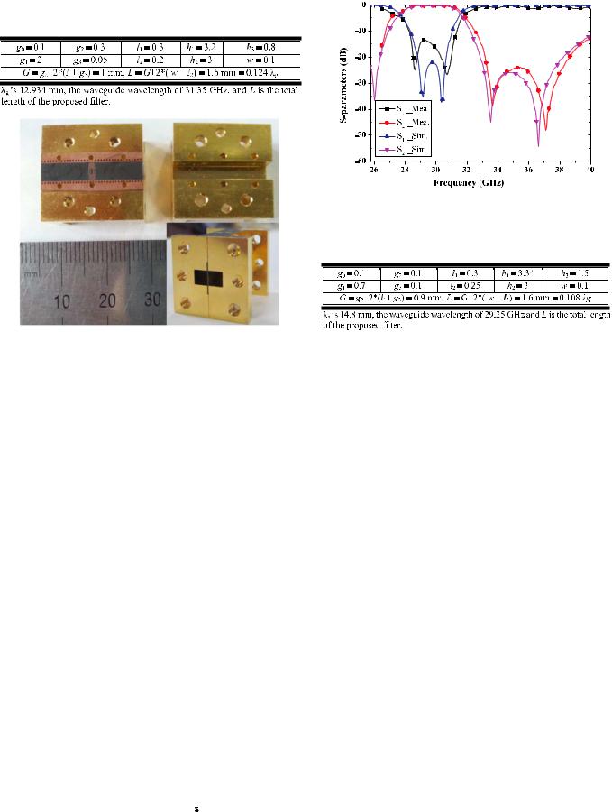
Fig. 9. Photograph of a proposed filter.
Besides, because of insertion of C-shaped resonators between the two CFSRs, the flexibility of adjustment of 
 is reduced.
III. CHARACTERISTICS AND EXPERIMENTS OF
THE PROPOSED FILTER
As illustrated in Section II, the proposed design method focuses on the design of the locations of the transmission zeroes. In this section, some important characteristics and experiments are presented.
A. Adjustment of Operating Frequencies
The key of the proposed method is to design the locations of the four transmission zeroes, which determine the operating frequencies and bandwidth. Two points must be considered. First, adjust the electrical length of the resonators to change their resonant frequencies. Second, adjust 
 and
and 
 to allocate the locations of transmission zeroes. Thus, the proposed filter can operate at different central frequencies with different bandwidths.
Here, an  -plane waveguide filter operating from 27.5 to 31 GHz for a wideband application is designed and fabricated. The structure is fabricated on the Duriod 5880 substrate with a thickness of 0.254 mm and relative permittivity of


 . The substrate is then inserted into the central
  -plane of the standard waveguide WR-28. Although the filter is only 1.6 mm in length of a waveguide, the substrate has a length of 20 mm for easy resemblingandmeasurement.Thephotograph ofthesubstrateand its associated waveguide structure are shown in Fig. 9. Comparisons of the simulation and measurement results are presented in Fig. 10. The parameters of the filter (except lengths of the input and output waveguide) are given in Table II and its length in transmission direction is only


 .
.
From the simulation results in Fig. 10, for slightly expanding the simulation frequency band, itcan be seen that there are three
IEEE TRANSACTIONS ON MICROWAVE THEORY AND TECHNIQUES
Fig. 10. Simulation and measurement results of the broadband  -plane waveguide filter.
TABLE II
DIMENSIONAL PARAMETERS (IN MILLIMETERS)
transmission zeroes with two located at 33.5 and 36.6 GHz in the upper stopband and one at 26 GHz in the lower stopband, which greatly improve the out-of-band rejection level. Because the nominated experimental frequency of the Ka-band standard waveguide system is from 26.5 to 40 GHz, the transmission zeroes in lower stopband cannot be measured to show. Two transmission zeroes at 33.66 and 37.1 GHz are clearly presented in the measurement results. The measured minimum insertion loss is only 0.2 dB and the 0.5-dB bandwidth is from 28.4 to 30.9 GHz with an absolute bandwidth of 2.5 GHz or a relative bandwidth of 8.4%. Slight frequency shift can be seen between the simulation and measurement results. This is because of the fabrication tolerance, resembling, and the material errors.
When the initial 
 is designed to have a large value because
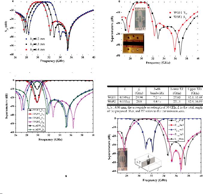
 is set to be 0.1 mm, which is the minimum feature that could be reliably fabricated, only one of the two lower transmission zeroes (the second one) can be displayed, as shown in Fig. 11. As illustrated in Fig. 5, changing
 does not change the electrical length of the CFSR, but adjust the locations of the two upper transmission zeroes. The upper two transmission zeroes are more separated under larger coupling of the CFSRs


 by increasing
 . Since larger
 leads to smaller
 due to the interaction among the resonators, the second lower transmission zero move towards the first one, which is not shown in Fig. 11. As a result, the operating frequencies of the filter shift without
changing its bandwidth and size.
B. Tunable Bandwidth
Controlling the locations of transmission zeroes can also adjust the operating band. As shown in Fig. 12, the simulation results show that three filters with different sizes are designed with the same center frequencies (about 30 GHz) and different bandwidths. Two of them (denoted by WGF1 and WGF2 in the figure) are fabricated. Measurement results are shown in
This article has been accepted for inclusion in a future issue of this journal. Content is final as presented, with the exception of pagination.
JIN et al.: NOVEL COMPACT |
|
-PLANE WAVEGUIDE FILTER WITH MULTIPLE TRANSMISSION ZEROES |
5 |
|||||||||||||||||||||||||||||
|
||||||||||||||||||||||||||||||||
|
||||||||||||||||||||||||||||||||
|
|
|
|
|
|
|
|
|
|
|
|
|
|
|
|
|
|
|
|
|
|
|
|
|
|
|
|
|
|
|
|
|
|
|
|
|
|
|
|
|
|
|
|
|
|
|
|
|
|
|
|
|
|
|
|
|
|
|
|
|
|
|
|
|
|
|
|
|
|
|
|
|
|
|
|
|
|
|
|
|
|
|
|
|
|
|
|
|
|
|
|
|
|
|
|
|
|
|
|
|
|
|
|
|
|
|
|
|
|
|
|
|
|
|
|
|
|
|
|
|
|
|
|
|
|
|
|
|
|
|
|
|
|
|
|
|
|
|
|
|
|
|
|
|
|
|
|
|
|
|
|
|
|
|
|
|
|
|
|
|
|
|
|
|
|
|
|
|
|
|
|
|
|
|
|
|
|
|
|
|
|
|
|
|
|
|
|
|
|
|
|
|
|
|
|
|
|
|
|
|
|
|
|
|
|
|
|
|
|
|
|
|
|
|
|
|
|
|
|
|
|
|
|
|
|
|
|
|
|
|
|
|
|
|
|
|
|
|
|
|
|
|
|
|
|
|
|
|
|
|
|
|
|
|
|
|
|
|
|
|
|
|
|
|
|
|
|
|
|
|
|
|
|
|
|
|
|
|
|
|
|
|
|
|
|
|
|
|
|
|
|
|
|
|
|
|
|
|
|
|
|
|
|
|
|
|
|
|
|
|
|
|
|
|
|
|
|
|
|
|
|
|
|
|
|
|
|
|
|
|
|
|
|
|
|
|
|
|
|
|
|
|
|
|
|
|
|
|
|
|
|
|
|
|
|
|
|
|
|
|
|
|
|
|
|
|
|
|
|
|
|
|
|
|
|
|
|
|
|
|
|
|
|
|
|
|
|
|
|
|
|
|
|
|
|
|
|
|
|
|
|
|
|
|
|
|
|
|
|
|
|
|
|
|
|
|
|
|
|
|
|
|
|
|
|
|
|
|
Fig.11. Simulationresults oftheproposedfilterversus |
|
|
(with |
|
|
|
|
|
|
|
|
|
|
|
mm, |
Fig. 13. Measurement results of two waveguide filters. |
||||||||||||||||||||||||||||||||||||||
|
|
|
|
|
|
|
mm, |
|
|
|
|
|
|
|
mm, |
|
|
|
|
|
|
|
|
|
|
|
|
|
|
|
|
|
|
|
|
|
mm, |
|
|
|
|
|
|
|
|
|
|
|
mm, |
|
||||
and |
|
|
|
|
|
|
|
|
|
mm). |
|
|
|
|
|
|
|
|
|
|
|
|
|
|
|
|
|
|
|
|
|
|
|
|
|
|
|
|
|
|
|
|
|
|
|
|
|
|
TABLE III |
|||||
|
|
|
|
|
|
|
|
|
|
|
|
|
|
|
|
|
|
|
|
|
|
|
|
|
|
|
|
|
|
|
|
|
|
|
|
|
|
|
|
|
|
|
|
|
|
|
|
|
|
|
|
|
|
|
COMPARISIONS OF MEASUREMENT RESULTS
Fig. 12. Simulation results of tunable bandwidth  -plane filters.
Fig. 13 and summarized in Table III. The measured insertion losses of WGF1 and WGF2 are 0.83 and 0.43 dB, respectively. Center frequencies are shifted from 30 to 29.94 GHz and 29.8 GHz with 7.2% and 9.4% bandwidths, respectively. The two filters are both less than 


 in length. The third
proposed filter (denoted by WGF3) is used to determine the minimum bandwidth of this kind of filter. When the simulation result of 

 at the center frequency is slightly less than
10 dB, the 3-dB bandwidth is supposed to be the minimum bandwidth, which is about 3.3%. Considering the locations of transmission zeroes can be designed outside of the Ka-band, the maximum bandwidth is not constrained here. Finally, the reason why only three transmission zeroes measured is the strong coupling of the two C-shaped resonators as well.
C. Half-Mode Waveguide Filter for Dual-Band Designing
With regard to the proposed filter, the  -plane of the waveguide is equivalent to an electrical wall considering the direction of the electric current of the resonators so the proposed filter can be cut into two and the cut-plane is replaced by a metal wall to construct the half-mode filter. The configuration of the half-mode filter is illustrated in Fig. 14, which is a half of the original designed configuration. It can be observed that the half-mode configuration has the same filtering characteristics, but with a half of the original one. This half-mode filter was not tested because of the limitation of fabrication and measurement
Fig. 14. Simulation results of half-mode filters and compared with the simulation and measurement results of relative full-mode filter.
difficulties.However,themeasured 

 oftherelativefull-mode configuration is presented for comparison in Fig. 14 as well. The measured central frequency is 30.88 GHz with a 3-dB relative bandwidth of 12.1% and the minimum insertion loss in the passband is 0.6 dB. Parameters of the full designed filter corresponding to the half-mode structure in Fig. 14 are given in Table IV. This kind of half-mode filter does reduce resonator sizes to half of the original one, which can be used to design more compact waveguide filters or design dual-band waveguide filters without enlarging the size.
Here, a compact dual-band waveguide filter is further investigated as shown in Fig. 15, where two different half-mode filters (denoted by HMF1 and HMF2) are separated by a metal wall whose thickness is 0.1 mm, in the central  -plane of the waveguide. The HMF1 with shorter
 and
and 
 (in full-mode configuration,


 mm and


 mm) can operate at the second passband. Whereas the HMF2 with larger
 and
and

This article has been accepted for inclusion in a future issue of this journal. Content is final as presented, with the exception of pagination.
6 |
IEEE TRANSACTIONS ON MICROWAVE THEORY AND TECHNIQUES |
TABLE IV
DIMENSIONAL PARAMETERS (IN MILLIMETERS)
Fig. 15. Simulation results of dual-band waveguide filter.

 (in full-mode configuration,


 mm,
mm, 


 mm, and


 mm) operates at the first passband of the dual-band waveguide filter. After combining the HMF1 and HMF2, a compact dual-mode waveguide filter is implemented and the simulation results are also given in Fig. 15.
D. Implantation in  -Plane Structures
Due to the miniature size of the proposed filter, it can be implanted in the  -plane structures, for example, finline, flexibly. Here, two typicaltransitions using a sinusoidal function are used to implement filtering transitions by implanting the proposed filter between the two fins at the ports of the transitions. The outer edge aligns with the start of the fins, which would not enlarge the size of the transitions. The filtering transitions are then inserted into the central
  -plane of the rectangular waveguide as the conventional configuration.
With the finline to microstrip transition, the proposed filter can be implanted into a finline environment, or via a sinusoidal taper, connected to the microstrip. Such a verification is given in Fig. 16(a). The finline to microstrip transition with 


 mm and


 mm can realize reflection loss
more 20 dB within almost an entire Ka-band, as shown in the subgraph of Fig. 16(a). It can be seen that by implanting the proposed filter the transition implements filtering performance while rotating the dominant mode 


 mode of the wave-
guide 90 and forming the electric field of the microstrip line. This filtering transition has the bandpass performance of the implanted filter whose simulation and measurement results are given in Fig. 14.
Another typical transition is the waveguide to slotline transition whose configuration and simulation results are shown in the subgraph of Fig. 16(b). The waveguide to slotline transition with 


 mm and


 mm can realize reflec-
tion loss more 20 dB within the entire band of interest. This
Fig. 16. Simulation results of filtering transitions. (a) Waveguide to microstrip transition. (b) Waveguide to slotline transition.
kind of filtering transition and its simulation results are shown in Fig. 16(b). The implanted filter is the one in Fig. 14 as well. Thus, it can be concluded that by implanting the proposed filter the transitions can realize filtering performance and keep the formal transformation without enlarging size.
IV. CONCLUSION
This paper has presented a novel compact waveguide bandpass filter with a length of less than 


 . This design introduced four transmission zeroes by four coupled resonators to improve the out-of-band rejection and the selectivity of the passband. A wideband filter is fabricated and tested and the insertion loss is only 0.2 dB. The proposed filter is very flexible in adjusting its bandwidth and center frequency. Further, the half-mode characteristic of this kind of filter is also investigated. It can be used to reduce the sizes of the resonators to half of the original ones and can be used to design dual-band waveguide filters without changing the total size. This new category of
  -plane waveguide filters has advantages of compactness and flexibility in design, making it a good candidate for many applications. The proposed filters can be implanted in
  -plane structures well. Besides, this kind of filter can be further miniaturized by arranging the two C-shaped resonators and the two CFSRs on the opposite side of the substrate.

This article has been accepted for inclusion in a future issue of this journal. Content is final as presented, with the exception of pagination.
JIN et al.: NOVEL COMPACT |
|
-PLANE WAVEGUIDE FILTER WITH MULTIPLE TRANSMISSION ZEROES |
7 |
|
|||
|
REFERENCES
[1]V. E. Boria and B. Gimeno, “Waveguide filters for satellites,” IEEE Microw. Mag., vol. 8, no. 5, pp. 60–70, Oct. 2007.
[2]P. Soto, E. Tarin, V. E. Boria, C. Vicente, J. Gil, and B. Gimeno, “Accurate synthesis and design of wideband and inhomogeneous inductive waveguide filters,” IEEE Trans. Microw. Theory Techn., vol. 58, no. 8,
pp.2220–2230, Aug. 2010.
[3]A. E. Atia and A. E. Williams, “Narrow-bandpass waveguide filters,”
IEEE Trans. Microw. Theory Techn., vol. MTT-20, no. 4, pp. 258–265, Apr. 1972.
[4]C. Tomassoni, S. Bastioli, and R. Sorrentino, “Generalized TM dualmode cavity filters,” IEEE Trans. Microw. Theory Techn., vol. 59, no. 11, pp. 3338–3346, Nov. 2011.
[5]S. Bastioli, C. Tomassoni, and R. Sorrentino, “A new class of waveguide dual-mode filters using TM and nonresonating modes,” IEEE Trans. Microw. Theory Techn., vol. 58, no. 12, pp. 3909–3917, Dec. 2010.
[6]Y. Konishi and K. Uenakada, “The design of a bandpass filter with inductive strip—Planar circuit mounted in waveguide,” IEEE Trans. Microw. Theory Techn., vol. MTT-22, no. 10, pp. 869–873, Oct. 1974.
[7]E. Ofli, R. Vahldieck, and S. Amari, “Novel  -plane filters and diplexers with elliptic response for millimeter-wave applications,”
IEEE Trans. Microw. Theory Techn., vol. 53, no. 3, pp. 843–851, Mar. 2005.
[8]N. Suntheralingam and D. Budimir, “Enhanced waveguide bandpass filters using S-shaped resonators,” Int. J. RF Microw. Comput.-Aided Eng., vol. 19, no. 6, pp. 627–633, Nov. 2009.
[9]D. Budimir, O. Glubokov, and M. Potrebic, “Waveguide filters using T-shaped resonators,” Electron. Lett., vol. 47, no. 1, p. 38, Jan. 2011.
[10]O. Glubokov and D. Budimir, “Extraction of generalized coupling coefficients for inline extracted pole filters with nonresonating nodes,”
IEEE Trans. Microw. Theory Techn., vol. 59, no. 12, pp. 3023–3029, Dec. 2011.
[11]J. Y. Jin, X. Q. Lin, Y. Jiang, L. Wang, and Y. Fan, “A novel  -plane substrate inserted bandpass filter with high selectivity and compact size,” Int. J. RF Microw. Comput.-Aided Eng., vol. 24, no. 4, pp. 451–456, Jul. 2014.
[12]N. Mohottige, U. Jankovic, and D. Budimir, “Ultra compact pseudoelliptic inline waveguide bandpass filters using bypass coupling,” in
IEEE MTT-S Int. Microw. Symp. Dig., 2014, pp. 1–4.
[13]X. Lin, J. Jin, Y. Jiang, and Y. Fan, “Metamaterial-inspired waveguide filters with compact size and sharp skirt selectivity,” J. Electromagn. Waves Appl., vol. 27, no. 2, pp. 224–232, Sep. 2013.
[14]X. Q. Lin, J. W. Yu, Y. Jiang, J. Y. Jin, and Y. Fan, “Electromagnetically induced transparencies in a closed waveguide with high efficiency and wide frequency band,” Appl. Phys. Lett., vol. 101, no. 9,
pp.093502–093502-03, Aug. 2012.
[15]J. S. Hong and M. J. Lancaster, Microwave Filters for RF/Microwave Applications. New York, NY, USA: Wiley, 2011.
Jun Ye Jin (S’11) was born in Inner Mongolia, China. She received the B.S. and M.S. degree in electromagnetics and microwave technology from the University of Electronic Science and Technology of China (UESTC), Chengdu, China, in 2011 and 2014, and is currently working toward the Ph.D. degree at the City University of Hong Kong, Hong Kong and Shenzhen Research Institute, City University of Hong Kong, Shenzhen, China.
She is currently with the State Key Laboratory of Millimeter Waves, Department of Electronic Engineering, City University of Hong Kong, Hong Kong, and Shenzhen Research
Institute, City University of Hong Kong, Shenzhen, China. Her research interests include microwave and millimeter-wave circuits and systems.
Xian Qi Lin (M’08–SM’15) was born in Zhejiang Province, China, on July 9, 1980. He received the B.S. degree in electronic engineering from the University of Electronic Science and Technology of China (UESTC), Chengdu, China, in 2003, and the Ph.D. degree in electromagnetic and microwave technology from Southeast University, Nanjing, China, in 2008.
In August 2008, he joined the Department of Microwave Engineering, UESTC, became an Associate Professor in July 2009 and a Doctoral Supervisor in
December 2011. From September 2011 to September 2012, he was a Post-Doc- toral Researcher with the Department of Electromagnetic Engineering, Royal Institute of Technology (KTH), Stockholm, Sweden. He is currently a Full Professor with UESTC. He has authored over 40 scientific journal papers and has presented over 20 conference papers. He holds over ten patents. His research interests include microwave/millimeter-wave circuits, metamaterials, and antennas.
Dr. Lin is a reviewer of many well-known journals such as the IEEE TRANSACTIONS ON MICROWAVE THEORY AND TECHNIQUES, the IEEE
TRANSACTIONS ON ANTENNAS AND PROPAGATION, IEEE MICROWAVE, WIRELESS, AND COMPONENTS LETTERS, Journal of Electromagnetic Waves and Applications/Progress In Electromagnetics Research, and Electronics Letters. He was the recipient of a 2011 Honorable Mention for the national hundred outstanding doctoral dissertations, a 2012 Excellent Young Scholar presented by UESTC, a 2013 New Century Excellent Talent in University presented by the State Ministry of Education.
Yuan Jiang (S’12) was born in Jiangsu Provence, China. He received the B.S. and M.S. degrees in electronic engineering from the University of Electronic Science and Technology of China (UESTC), Chengdu, China, in 2010 and 2012, respectively, and is currently working toward the Ph.D. degree at UESTC.
His research interests include microwave passive components,activecomponents,andantennas,with a special focus on reconfigurable/tunable technologies.
Quan Xue (M’02–SM’04–F’11) received the B.S., M.S., and Ph.D. degrees in electronic engineering from the University of Electronic Science and Technology of China (UESTC), Chengdu, China, in 1988, 1990, and 1993, respectively.
In 1993, he joined UESTC, as a Lecturer. In 1997, he became a Professor. From October 1997 to October 1998, he was a Research Associate and then a Research Fellow with the Chinese University of Hong Kong. In 1999, he joined the City University of Hong Kong, where he is currently a Chair Professor
of microwave engineering. He is also the Director of Information and Communication Technology Center (ICTC Center), the Deputy Director of the CityU Shenzhen Research Institute, and the Deputy Director of the State Key Laboratory of Millimeter Waves, Hong Kong. From June 2011 to January 2015, he was the Associate Vice President (Innovation Advancement and China Office). He has authored or coauthored over 260 internationally referred journal papers and over 100 international conference papers. His research interests include microwave passive components, active components, antennas, microwave monolithic integrated circuits (MMICs), and RF integrated circuits (RFICs).
Prof. Xue has served the IEEE as an IEEE Microwave Theory and Techniques Society (IEEE MTT-S) Administrative Committee (AdCom) member (2011–2013) and as an associate editor for the IEEE TRANSACTIONS ON MICROWAVE THEORY AND TECHNIQUES (2010–2013) and as an associate editor for the IEEE TRANSACTIONS ON INDUSTRIAL ELECTRONICS (2010–present).