

диафрагмированные волноводные фильтры / 4d94fef6-d094-4f10-b6a7-fffa69fff1e3
.pdfIEEE TRANSACTIONS ON MICROWAVE THEORY AND TECHNIQUES, VOL. 54, NO. 11, NOVEMBER 2006 |
3885 |
Efficient Analysis, Design, and Filter Applications of EBG Waveguide With Periodic Resonant Loads
George Goussetis, Member, IEEE, Alexandros P. Feresidis, Member, IEEE, and Panagiotis Kosmas, Member, IEEE
Abstract—An efficient analysis and design of an electromag- netic-bandgap (EBG) waveguide with resonant loads is presented. Equivalent-circuit analysis is employed to demonstrate the differences between EBG waveguides with resonant and nonresonant loadings. As a result of the resonance, transmission zeros at finite frequencies emerge. The concept is demonstrated in  -plane waveguides. A generic fast and efficient formulation is presented, which starts from the generalized scattering matrix of the unit cell and derives the dispersion properties of the infinite structure. Both real and imaginary parts of the propagation constant are derived and discussed. The Floquet wavelength and impedance are also presented. The theoretical results are validated by comparison with simulations of a finite structure and experimental results. The application of the proposed EBG waveguide in the suppression of the spurious passband of a conventional
  -plane filter is presented by experiment.
Index Terms—Electromagnetic bandgap (EBG),  -plane filters, waveguide.
I. INTRODUCTION
LECTROMAGNETIC-BANDGAP (EBG) structures Ehave received increased attention in recent years [1], [2]. EBG structures have a frequency band in which no electromagnetic (EM) mode can propagate. Furthermore, at other frequencies, EBG structures have the property of reducing the phase velocity of EM modes according to the slow wave effect. Typically, the EBG property emerges by virtue of periodic reactive loading of the guiding structure. In the general case and adopting a circuit model, loads can be inductive (L), capacitive (C) or resonant (both L and C) in either series or shunt topology [3]. While the stopband–passband and slow-wave effects that are produced in all cases have similarities [3], [4], some important differences emerge. These can be anticipated using simple equivalent circuits. In practice, periodic loads are often realized by distributed structures, typically leading to configurations with successive discontinuities.
According to their geometrical characteristics and spatial properties, EBG structures can be divided into three-dimen-
Manuscript received April 17, 2005; revised June 30, 2006. The work of G. Goussetis was supported by the Royal Academy of Engineering under a five-year research fellowship.
G. Goussetis is with the School of Engineering and Physical Sciences, HeriotWatt University, Edinburgh EH14 AS, U.K., and also with the Edinburgh Research Partnership, Institute of Integrated Systems, Edinburgh EH14 AS, U.K. (e-mail: g.goussetis@ieee.org).
A. P. Feresidis is with the Department of Electrical and Electronic Engineering, Loughborough University, Loughborough LE11 3TU, U.K. (e-mail: a.feresidis@ieee.org).
P. Kosmas is with the Hellenic Navy, Greece (e-mail: pkosmas@coe.neu. edu).
Digital Object Identifier 10.1109/TMTT.2006.883648
Fig. 1. Layout of the E-plane EBG waveguide.
sional (e.g., [5]), twodimensional (e.g., [6] and [7]), or one-dimensional (e.g., [8]). Twoand three-dimensional EBGs often find applications as substrates for printed antennas [9], in mobile handsets [10], [11], and other applications [12]. One-dimensional EBGs have been employed as slow wave structures, e.g., in slot array antennas [13]. In waveguide housing, periodically loaded (serrated) waveguides have been demonstrated to provide a variable refractive index [14] and have been employed for low-pass filtering applications [15], [16]. More recently it has been proposed to replace the homogeneous waveguide sections in the resonators of  -plane filters [17] with periodically loaded waveguides in order to reduce the physical size and stopband performance.
In this study, we present a thorough analysis, as well as design techniques for EBG waveguides with periodic resonant loadings. As an example, we study the rectangular waveguide periodically loaded on the  -plane with ridges (Fig. 1). Initially, a qualitative equivalent-circuit analysis is employed in order to demonstrate the effects of the resonant as opposed to pure inductive shunt loading. It is demonstrated that the addition of a series capacitance in the shunt inductive loading leads to a low-pass response with a transmission zero in the stopband. Subsequently, a rigorous and robust full-wave formulation based on the generalized scattering matrix (GSM) of the unit cell is employed for the fast and accurate derivation of the complex wavenumber for an infinite structure. The field distribution of each Floquet mode is derived from the eigenvector corresponding to each eigenvalue. Based on the field distribution, impedance estimations for each mode are subsequently derived. The theoretical results are validated by means of simulating and experimentally assessing a finite low-pass structure. Finally, an application of the proposed EBG waveguide in improving the stopband performance of
  -plane filters is presented.
0018-9480/$20.00 © 2006 IEEE

3886 |
IEEE TRANSACTIONS ON MICROWAVE THEORY AND TECHNIQUES, VOL. 54, NO. 11, NOVEMBER 2006 |
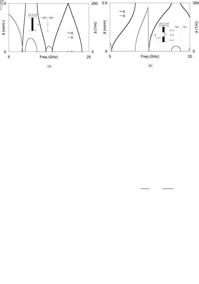
Fig. 2. Dispersion diagram ( f and |
f) for periodically loaded X-band waveguides from equivalent-circuit unit cell with: (a) inductive load (Lw = 24 mm, |
L = 0:2 nH) and (b) resonant load (Lw |
= 8 mm, L = 0:7 nH, C = 0:183 pF). |
II. DISPERSION RELATION FROM EQUIVALENT CIRCUITS
Two circuit configurations are initially considered here, one periodically loaded with shunt inductors (L) and another periodically loaded with series resonators (LC) in shunt topology. The unit cells are shown as insets in Fig. 2. For the inductive unit cell [see Fig. 2(a)], the periodicity is 


 mm, while for the resonant unit cell [see Fig. 2(b)],


 mm. In order to account for the waveguide properties of the homogeneous section of the transmission line between successive shunt loads, dispersive lines that follow the properties of the waveguide
  -band
-band 


 mode have been modeled between successive modes. The dispersion properties of the topology can be easily obtained, e.g., following simple circuit analysis to obtain the


 -parameters and subsequently applying Floquet theorem, as described in [18]
where 


 is the complex wavenumber. The real and imaginary parts of the Floquet wavenumber are shown in Fig. 2. From the imaginary part
  of the complex wavenumber, we identify the first passband for the EBG transmission line with shunt inductive loading [see Fig. 2(a)] in the range of 8–9 GHz. At the upper cutoff (9.06 GHz), the unit cell length is equal to a half guided wavelength, and Bragg reflections produce the bandgap. Considering that the dispersion of the
  -band waveguide only allows for modes above 6.56 GHz, the lower cutoff of the structure of Fig. 2(a) (8.09 GHz) suggests an overall bandpass response for this structure.
For the EBG transmission line with shunt resonant loading, the first-order mode is found to be between 6.56–11.48 GHz [see Fig. 2(b)]. The lower cutoff is the cutoff of the  -band waveguide, indicating a low-pass response. Due to the smaller periodicity, the Bragg condition is in this case satisfied at 19.86 GHz, which corresponds to the cutoff of the second-order mode. The first bandgap, between 11.39–15.35 GHz in this case, emerges by virtue of the band reject characteristics of the shunt load.
The real part of the wavenumber corresponds to the rate of attenuation of the wave as it propagates along  . Assuming no ohmic losses, the attenuation in the passband is zero. In
the bandgap, any incident excitation decays exponentially, according to 


 . Hence, the nonzero values of
  correspond to the bandgaps. The variation of
  in the bandgap for the circuit of Fig. 2(a) is smooth with values varying well below 100 m
 . However, for the circuit of Fig. 2(b), the attenuation constant shows a sharp peak at the frequency


 GHz, raising the values of the attenuation constant at the vicinity to well above 200 m
 . This is the resonant frequency of the shunt load, at which the load behaves as a short circuit. The peak, therefore, corresponds to the transmission zero, the frequency of which is determined not by the periodicity, but rather by the resonance of the LC circuit.
III. DISTRIBUTED STRUCTURE: FULL-WAVE
DISPERSION CHARACTERIZATION
The inductive loadings in a waveguide are realized in practice by bifurcating  -plane metal septa, as shown in the inset of Fig. 3(a) [19]. These discontinuities find application in the well-established
  -plane filters [19]. When positioned at distances


 apart, and their equivalent length is carefully selected, bandpass responses can be produced. In those structures, the passband corresponds to the first-order mode, while the stopband emerges due to the following bandgap. A capacitance in series with the inductance can be introduced by opening a gap in the
  -plane posts [inset in Fig. 3(b)]. The capacitance is, in this case, formed in the gap between the two ridges. In this manner, a resonant (LC) load is produced, which is expected to perform in a similar manner with the circuit of Fig. 2(b).
In order to accurately analyze the distributed structure of Fig. 1, a rigorous full-wave modeling analysis that takes into account higher order mode interaction is necessary. In [20] and the references therein, the determination of Floquet modes is based on an eigenvalue problem for the transmission matrix of the unit cell. This method is, however, potentially unstable due to the exponential terms with positive real arguments that appear in the evanescent modes of a homogeneous waveguide section [21]. In [22], the impedance matrix formulation of the mode-matching technique was employed in order to derive a second-order polynomial eigenvalue equation. A canonical formulation based on the GSM, which can be readily solved using available numerical routines, has been developed [21]. While
GOUSSETIS et al.: EFFICIENT ANALYSIS, DESIGN, AND FILTER APPLICATIONS OF EBG WAVEGUIDE |
3887 |
Fig. 3. Full-wave dispersion diagram ( f and Lr = 5 mm) and (b) ridge waveguide discontinuity (Lw
f ) for periodically loaded X-band waveguides with: (a) bifurcate E-plane septum (Lw = 20 mm, = 6 mm, Lr = 2 mm, s = 1 mm). Thickness of inserts is everywhere t = 0:1 mm.
this method avoids the need for matrix inversions, in practice, it has proven to be numerically unstable for a large number of modes and expansion terms. Reference [23] proposed an alternative canonical eigenvalue admittance matrix formulation, which involves one substitution and a matrix inversion. Here we present a formulation that applies the transformation of [23] in a GSM description of the unit cell and brings the problem into canonical eigenvalue form. The GSM of the unit cell can be obtained upon application of the generalized transverse resonance technique and the mode-matching method [24].
Due to the orthogonality of the modal description in each section of the unit cell, the Floquet condition is applied to each mode separately. Hence, assuming the propagation constant of the Floquet eigenmode to be 
and can rearrange (4) in the form
(6)
Equation (6) is now in the classical canonical form and can be solved fast and accurately using well-established routines. Assuming the ridge waveguide load symmetrically located within the unit cell, we can take advantage of the following symmetry properties:
(1)The real and imaginary parts of the Floquet propagation con-
(2) |
stant |
can be directly derived from the propagation |
constant by |
|
|
|
|
where the coefficient vectors at the two ends of the unit cell are related through the GSM
(3)
Combining (1)–(3), we can obtain
(4)
where
(4a)
(4b)
(4c)
In order to bring (4) in the classical canonical form 


 , we introduce the substitutions
(5)
With this formulation, both real and imaginary parts of the propagation constant can be efficiently determined. Furthermore, using the calculated eigenvectors, it is straightforward to obtain  and
and 
 , from which we can obtain the field distribution of each Floquet mode. The method is an accurate and efficient way of obtaining the dispersion relation of a generic periodic structure based on the GSM of the unit cell. For a


 incidence and symmetrical ridges, it is sufficient to analyze only one-quarter of the cross section. In this case, the structure satisfies magnetic wall symmetry at


 and electric wall symmetry at


 . Even modes along
  and odd modes along
  can, in this case, be excluded from the analysis.
The use of the GSM ensures instabilities from exponentially growing evanescent modes are prevented. In practice, however, we have noticed that the method is prone to numerical errors when the order of the GSM is large enough to include localized modes, which decay to a negligible level between successive discontinuities. This problem can be fixed by truncating the
3888 |
IEEE TRANSACTIONS ON MICROWAVE THEORY AND TECHNIQUES, VOL. 54, NO. 11, NOVEMBER 2006 |
GSM to those accessible modes, whose amplitude along the homogeneous parts of the unit cell is maintained above a certain threshold.
In solving the canonical problem (6), the number of eigenvalues  obtained is typically equal to the order of the total matrix in the left-hand side of (6). These eigenvalues come into pairs, corresponding to forward and backward directions of the same mode. For each direction, the solution of (6) yields Floquet modes of the first and higher orders. Higher order modes are, in general, distinguished from their increased attenuation, i.e., higher value of
  . In the lower frequency range, the firstorder mode is propagating and higher order modes are evanescent. Similarly, within the bandgap, it is typical for higher order modes to attenuate faster. This is, in general, true with the exception of the frequency range around the transmission zero. At those frequencies, it is possible for the attenuation rate of the first Floquet mode to obtain greater values than the next mode. This occurs due to the short circuit experienced by the first-order mode. Therefore, the “lowest real
  ” criterion for the selection of the fundamental Floquet mode can lead to mistakes regarding the attenuation constant of a mode in the region of the transmission zero.
Instead, selection of the Floquet mode of interest is preferably based on inspection of the corresponding field distribution. In practice, one way to do that is to identify the dominant rectangular waveguide TE or TM component of the Floquet mode of interest. At the edge of the unit cell, each Floquet mode is expressed as a linear combination of forward and backward TE and TM modes with projections described by the vectors  and
and 
 . The maximum element within the vector


 corresponds to the dominant TE or TM component of the Floquet mode. For the first-order mode, this is the


 mode, which corresponds to either
  (1) or
 (1), depending on the assumed direction. Selecting the eigenvector whose maximum absolute value element is either of
  (1) or
 (1) is a stable criterion for selecting the first-order mode even in the neighborhood of the transmission zero.
In order to give an estimation of the computational time required, we report that a typical dispersion diagram with 100 points, 30 TE and 20 TM modes in each section takes approximately 24 s on a Pentium 4 at 2 GHz with 1-GB RAM. This is many orders of magnitude reduced compared to generic commercially available software packages.
IV. EBG RIDGE WAVEGUIDE
A full-wave analysis of the EBG waveguides with unit cells shown in Fig. 3 has been carried out. Throughout this study, we have considered  -band waveguide housing, while the thickness of the metal insert is 100
  m, small enough to be compatible with standard photolithographic techniques.
The dispersion relations obtained with the full-wave method of Section III for both the real and imaginary parts of the propagation constant are shown in Fig. 3. For the inductive unit cell of Fig. 3(a), the dimensions are 


 mm and


 mm (i.e., periodicity


 mm). As mentioned above, this topology can also be seen as a bandpass
  -plane filter [17] in the limit of infinite order. The passband will then correspond to the
propagating mode and the stopbands to the bandgaps. For the resonant unit cell of Fig. 3(b), the dimensions are 


 mm,
mm, 


 mm (i.e., periodicity

 mm), and

 mm. The correspondence between the obtained responses from the equivalent circuits and the full-wave analysis of the distributed structures is evident. This clearly demonstrates the resonant behavior of the ridge waveguide sections, as opposed to the inductive behavior of the bifurcating septa.
In the remainder of this section, we present propagation characteristics of the  -plane EBG waveguide that assist with the design. Parametric studies of the complex dispersion relation are given, together with theoretical calculation of the Floquet wavelength and impedance.
A. Dispersion Relations 


Fig. 4 shows the dispersion relation of EBG waveguides with fixed load length 


 mm and variable periodicity. The dispersion relation of the


 mode is also superimposed via a light gray dotted line for comparison. At low frequencies, the dispersion characteristics of the EBG waveguides resemble those of the homogeneous case, but the dispersion curves deviate, leading to a bandgap at the edge of the Brillouin zone. Note that for the smallest periodicity
  and for larger gaps
  , the bandgap of the first-order mode emerges at higher frequencies than the cutoff frequency of the second-order mode. The lower cutoff frequency of the first-order mode is, in all cases, below the cutoff frequency of the


 mode and above the cutoff frequency of the corresponding homogenous ridge waveguide, tending to the former for larger unit cells and to the latter for smaller unit cells. The bandgap of the first-order mode (upper cutoff frequency) drops for smaller gaps or larger unit cells and the bandgap width is larger for those cases.
B. Attenuation Constant 


Attenuation constant curves 


 give a good indication of how fast the field decays in the EBG waveguide and are, therefore, particularly useful in determining the order of low-pass filters. Fig. 4 also shows the variation of the attenuation constant of the EBG ridge waveguides with frequency. Since the analysis considers the lossless case,
  is zero in the passbands and assumes nonzero values in the bandgaps. The transmission zero predicted from the circuit analysis appears as the sharp peaks in Fig. 4. These peaks correspond to the frequency where the ridges themselves resonate and, hence, the EBG waveguide appears short circuited. As the periodicity is reduced, the frequency of the transmission zero increases and the levels of attenuation increase.
In order to probe further into the nature and properties of the transmission zero, Fig. 5 shows the variation of the attenuation constant  for the case of


 mm and


 mm and the gap
  between the ridges varying between 0.5–2 mm. It is clearly shown that, for narrower gaps, the transmission zero moves towards lower frequencies due to the increased capacitance between the ridges. On the contrary, by increasing this gap, the capacitance is reduced and the transmission zero moves to higher frequencies, moving to the second-order bandgap for the highest values of the gap. There is a gapwidth value where the second mode of the structure is nearly eliminated by the transmission

GOUSSETIS et al.: EFFICIENT ANALYSIS, DESIGN, AND FILTER APPLICATIONS OF EBG WAVEGUIDE |
3889 |
Fig. 4. Dispersion relation (top) and attenuation constant (bottom) for the E-plane EBG waveguide with unit cell: (a) 12, (b) 8, and (c) 4 mm and gaps 1, 3, and 5 mm.
zero. This result can also be predicted from the equivalent-cir- cuit analysis.
C. Floquet Wavelength
In a frequency range below the bandgap, periodic structures typically support waves whose velocity of propagation is reduced compared to that in the homogeneous host medium. As a result, the wavelength of the Floquet mode is reduced compared to the wavelength of the unperturbed medium, which, in this case, is the rectangular waveguide. In an equivalent medium description, the periodically loaded medium exhibits an increased refractive index [14], [25], which can be calculated from the
ratio of the free space over the Floquet wavelength at the operating frequency. These properties find tangible applications in traveling-wave tubes [3], microwave lenses [14], and miniaturized microwave filters [17]. The Floquet wavelength can be readily estimated from the dispersion diagrams 


 according to
Fig. 6 shows the Floquet wavelength for the structure with 


 mm, and

 mm and gap values
  equal to 1, 3,

3890 |
IEEE TRANSACTIONS ON MICROWAVE THEORY AND TECHNIQUES, VOL. 54, NO. 11, NOVEMBER 2006 |
Fig. 5. Attenuation constant versus frequency for EBG waveguide with unit cell 12 mm, Lrid 2 mm and varying gap between the ridges.
Fig. 7. Bloch impedance (magnitude and phase) for the EBG waveguide with Lred = 2 mm and D = 8 mm (gap = 1 mm). The impedance of the unperturbed TE10 is also shown for comparison.
Fig. 6. Guided wavelength for the EBG waveguide with Lr = 2 and D = 4 and gaps 1, 3, and 5 mm. The guided wavelength of the TE10 mode is shown for comparison.
and 5 mm. For comparison, the wavelength of the unperturbed 


 mode is also shown. A wavelength reduction of around 50% is observed between


 and the waveguide with a gap
of 1 mm at around 10 GHz. This can be translated, for example, in reduction of overall dimensions in filter applications [17].
D. Bloch Impedance
The characteristic impedance of an infinite periodic structure is typically assumed to be the Bloch impedance at the unit cell terminals [18], and is obtained as the ratio of an equivalent voltage over an equivalent current. Since the unit cell terminals are rectangular waveguides, the equivalent voltage and current are not uniquely defined. Here, we use the voltage/current definition as the line integral of the electric/magnetic field along the plane of magnetic/electric symmetry of the 


 mode
mode
The electric and magnetic fields at the unit cell terminals can be reconstructed for each eigenvalue  from the corresponding eigenvector


 and the analytically determined rectangular waveguide modes. Fig. 7 shows the calculated Bloch
impedance (magnitude and phase) for the EBG waveguide with 


 mm,
mm, 

 mm, and

 mm. For comparison, the magnitude of the impedance of the unperturbed waveguide is also superimposed. Overall, the effect of the periodic loading is to shift the curve to lower frequencies and lower impedance values. Up to 5.4 GHz, the EBG waveguide is below cutoff and the impedance is imaginary, as is the case with the standard rectangular waveguide below cutoff. The first Floquet mode extends between 5.4–11.6 GHz. Within the range of 5.4–6.6 GHz, the EBG waveguide is, therefore, above cutoff, while the corresponding rectangular waveguide is below cutoff. The propagating Floquet mode can be analyzed in this section of the unit cell as a linear combination of accessible evanescent rectangular waveguide modes, which interact between successive discontinuities. At this frequency range, the impedance is real, but negative. Between 6.6–11.6 GHz the impedance phase is nearly zero, as the case with the rectangular waveguide. In the bandgap, the impedance becomes nearly imaginary, with a phase of approximately 90
 . Above the first bandgap, at 15.8 GHz, the impedance again becomes nearly real and
positive, only now shifted to higher values.
V. FINITE STRUCTURES
The dispersion curves derived with the method described in Section II can be used as guidelines for the design of waveguide filters. The propagating modes and bandgaps identified in the dispersion diagrams correspond to passbands and stopbands of finite structures provided those are impedance matched. The EBG ridged waveguide sections have a low-pass mode whose upper cutoff is defined from the unit cell dimensions together with the gap between the two ridges. The order of the low-pass filter, i.e., the number of loads of the finite structure, defines the attenuation in the stopband. This can be estimated taking into account the real part of the propagation constant  considering that the waves decay in a finite EBG waveguide according to


 . Hence, the required length
  for a specified isolation can be derived. This is subsequently translated to numbers of unit cells. The other consideration for the designer is to match the EBG waveguide impedance to the rectangular


 -mode impedance. This can be achieved by altering the dimensions of

GOUSSETIS et al.: EFFICIENT ANALYSIS, DESIGN, AND FILTER APPLICATIONS OF EBG WAVEGUIDE |
3891 |
Fig. 8. Simulated mode matching and measured results for a fifth-order lowpass prototype. Dots show S12 as estimated from the attenuation constant of the infinite structure.
TABLE I
DIMENSIONS OF FABRICATED PROTOTYPE
for the complete finite structure. Very good agreement is observed between the two. Furthermore, the estimation of the attenuation from the calculated value of  [see Fig. 4(b)] is shown with dots in Fig. 8. The good agreement between the finite structure and the prediction of its response from the infinite structure validates the accuracy of the estimated values of
  and demonstrates its usefulness in determining the order of the EBG filter.
To demonstrate an application of the proposed waveguide, this low-pass filter has been integrated with an  -plane bandpass filter in order to suppress the spurious harmonic resonance of the latter. A prototype has been fabricated and tested. The measured response and a photograph of the prototype are shown in Fig. 9. In the same figure, the simulated

 of the bandpass filter alone is also shown. The stopband of the
  -plane filter, which originally extended up to approximately 12.5 GHz, now extends to approximately 15 GHz, without any associated increase in the fabrication complexity.
VI. CONCLUSION
Fig. 9. Measured response and photograph of fabricated third-order E-plane filter integrated with the low-pass structure of Fig. 8 for suppression of spurious passband.
the first and last loadings. As an example of a low-pass filter, Fig. 8 shows the response of a fifth-order filter with cutoff at 11.5 GHz. This filter has been employed for the suppression of the first spurious harmonic passband of a bandpass  -plane filter [16]. The designed dimensions are given in Table I. The filter has been fabricated and measured. The experimental results are shown in Fig. 8 together with mode-matching results
A rigorous study of the  -plane EBG waveguide with resonant loads has been presented. Equivalent circuits have been employed to demonstrate the effect of opening a capacitive gap in the otherwise inductive
  -plane posts. The resulting load, as opposed to the inductive nature of the
  -plane post, is resonant. A low-pass performance is produced and a transmission zero emerged in the bandgap due to the resonance of the load. An efficient full-wave formulation based on the GSM has been employed for the full-wave characterization of the structure. The location of the transmission zero was shown to be adjusted with the geometry of the capacitive gap. The effective wavelength and impedance have been rigorously calculated. Experimental results on a finite structure have been presented and are in good agreement with the simulated results for the finite and truncated infinite structure, thus validating the analysis. The proposed structure is compatible with standard low-cost photolithographic techniques of
  -plane technology and can be directly integrated with well-established
  -plane filters. As an example, an application for the suppression of the spurious passband of a bandpass
  -plane filter was presented.
ACKNOWLEDGMENT
The authors would like to thank Dr. R. Tascone, L’Istituto di Elettronica e di Ingegneria dell’Informazione e delle Telecomunicazioni (IEIIT), Consiglio Nazionale delle Ricerche (CNR), Turin, Italy, for the fruitful discussions regarding the algebraic formulation.
REFERENCES
[1]IEEE Trans. Antennas Propag. (Special Issue), vol. 51, no. 10, Oct. 2003.
[2]IEEE Trans. Antennas Propag. (Special Issue), vol. 53, no. 1, Jan. 2005.
[3]A. F. Harvey, “Periodic and guiding structures at microwave frequencies,” IRE Trans. Microw. Theory Tech., vol. MTT-8, no. 1, pp. 30–61, Jan. 1959.
[4]R. Collin, Foundations for Microwave Engineering. New York: Mc- Graw-Hill, 1966.
[5]E. Yablonovitch, T. J. Gmitter, and K. M. Leung, “Photonic band structure: The face-centered cubic case employing nonspherical atoms,” Phys. Rev. Lett., vol. 67, no. 17, pp. 2295–2298, Oct. 1991.

3892 |
IEEE TRANSACTIONS ON MICROWAVE THEORY AND TECHNIQUES, VOL. 54, NO. 11, NOVEMBER 2006 |
[6]D. Sievenpiper, Z. Lijun, R. F. Broas, N. G. Alexopoulos, and E. Yablonovitch, “High-impedance electromagnetic surfaces with a forbidden frequency band,” IEEE Trans. Microw. Theory Tech., vol. 47, no. 11, pp. 2059–2074, Nov. 1999.
[7]F.-R. Yang, K.-P. Ma, Y. Qian, and T. Itoh, “A uniplanar compact photonic-bandgap (UC-PBG) structure and its applications for microwave circuit,” IEEE Trans. Microw. Theory Tech., vol. 47, no. 8, pp. 1509–1514, Aug. 1999.
[8]J.-S. Hong and B. M. Karyamapudi, “A general circuit model for defected ground structures in planar transmission lines,” IEEE Microw. Wireless Compon. Lett., vol. 15, no. 10, pp. 706–708, Oct. 2005.
[9]H. Mosallaei, K. Sarabandi, and K. , “Antenna miniaturization and bandwidth enhancement using a reactive impedance substrate,” IEEE Trans. Antennas Propag., vol. 52, no. 9, pp. 2403–2414, Sep. 2004.
[10]R. F. Broas, D. Sievenpiper, and E. Yablonovitch, “An Application of high-impedance ground planes to phased array antennas,” IEEE Trans. Antennas Propag., vol. 53, no. 4, pp. 1377–1381, Apr. 2005.
[11]G. Goussetis, A. Feresidis, G. Palikaras, M. Kitra, and J. C. Vardaxoglou, “Miniaturised electromagnetic bandgap structures for reducing handset antenna detuning due to human hand,” Radio Sci., vol. 40, Nov. 2005, RS6S04.
[12]R. Abhari and G. V. Eleftheriades, “Metallo-dielectric electromagnetic bandgap structures for suppression and isolation of the parallel-plate noise in high-speed circuits,” IEEE Trans. Microw. Theory Tech., vol. 51, no. 6, pp. 1629–1639, Jun. 2003.
[13]A. J. Sangster, “Radiating apertures in a corrugated rectangular waveguide,” Electron. Lett., vol. 9, no. 15, pp. 329–331, Jul. 1973.
[14]H. S. Kirschbaum and R. Tsu, “A study of the serrated ridge waveguide,” IRE Trans. Microw. Theory Tech., vol. MTT-7, no. 1, pp. 142–148, Jan. 1959.
[15]A. M. K. Saad, “Novel lowpass harmonic filters for satellite application,” in IEEE MTT-S Int. Microw. Symp. Dig., May 1984, vol. 84, no. 1, pp. 292–294.
[16]G. Goussetis and D. Budimir, “Compact ridged waveguide filters with improved stopband performance,” in IEEE MTT-S Int. Microw. Symp. Dig., Jun. 2003, vol. 2, pp. 953–956.
[17]G. Goussetis and D. Budimir, “Novel periodically loaded E-plane
filters,” IEEE Microw. Wireless Compon. Lett., vol. 13, no. 6, pp. 193–195, Jun. 2003.
[18]D. Pozar, Microwave Engineering. Reading, MA: Addison-Wesley, 1993.
[19]J. Uher, J. Bornemann, and U. Rosenberg, Waveguide Components for Antenna Feed Systems: Theory and CAD. Norwood, MA: Artech House, 1993.
[20]R. Orta, R. Tascone, and R. Zich, “Three-dimensional periodic arrays of thin conductors,” Electromagnetics, vol. 7, pp. 185–203, 1987.
[21]W. S. Best, R. J. Riegert, and L. C. Goodrich, “Dispersion analysis of the linear vane-type waveguide using the generalized scattering matrix,” IEEE Trans. Microw. Theory Tech., vol. 43, no. 9, pp. 2101–2107, Sep. 1995.
[22]J. Esteban and J. M. Rebollar, “Characterization of corrugated waveguides by modal analysis,” IEEE Trans. Microw. Theory Tech., vol. 39, no. 6, pp. 937–943, Jun. 1991.
[23]S. Amari, R. Vahldieck, J. Bornemann, and P. Leuchtmann, “Spectrum of corrugated and periodically loaded waveguides from classical matrix eigenvalues,” IEEE Trans. Microw. Theory Tech., vol. 48, no. 3, pp. 453–460, Mar. 2000.
[24]G. Goussetis and D. Budimir, “Waveguide filters with improved stopband performance,” in 30th Eur. Microw. Conf. Dig., Paris, France, Oct. 2–6, 2000.
[25]G. Goussetis, A. P. Feresidis, S. Wang, Y. Guo, and J. C. Vardaxoglou, “Uniplanar left-handed artificial metamaterials,” J. Opt. A (Special Issue), vol. 7, no. 2, pp. 44–50, Feb. 2005.
George Goussetis (M’01) was born in Athens, Greece, in 1976. He received the Electrical and Computer Engineering degree from the National Technical University of Athens, Athens, Greece, in 1998, the Ph.D. degree in waveguide filters from the University of Westminster, Westminster, U.K., in 2002, and the B.Sc. degree in physics from University College London (UCL), London, U.K., in 2002.
In 1998, he joined the Space Engineering, Rome, Italy, as Junior RF Engineer. In 1999, he joined the Wireless Communications Research Group, University of Westminster, as a Re-
search Assistant. He is currently a Lecturer with the School of Engineering and Physical Sciences, Heriot-Watt University, Edinburgh, U.K. He has authored or coauthored over 70 peer-reviewed journals and conference papers. His research interests include the modeling and design of microwave filters, frequency-se- lective surfaces, and EBG structures, as well numerical techniques for electromagnetics.
Dr. Goussetis was the recipient of a 2006 five-year research fellowship presented by the Royal Academy of Engineers, U.K.
Alexandros P. Feresidis (S’98–M’01) was born in Thessaloniki, Greece, in 1975. He received the Physics degree from Aristotle University of Thessaloniki, Thessaloniki, Greece, in 1997, the M.Sc.(Eng.) degree in radio communications and high-frequency engineering from The University of Leeds, Leeds, U.K., in 1998, and the Ph.D. degree in electronic and electrical engineering from Loughborough University, Loughborough, U.K., in 2002.
During the first half of 2002, he was a Research Associate and in the same year was appointed Lecturer of wireless communications with the Department of Electronic and Electrical Engineering, Loughborough University. He is currently a Senior Lecturer with the same department. He has authored or coauthored over 60 papers in peer-reviewed international journals and conference proceedings. His research interests include analysis and design of artificial periodic metamaterials, EBG structures and frequency-selective surfaces (FSSs), high-gain array antennas, base-station antennas, and numerical techniques in electromagnetics and microwave circuits.
Panagiotis Kosmas (S’03–M’05) received the Diploma degree in electrical and computer engineering from the National Technical University of Athens, Athens, Greece in 1999, and the M.S. and Ph.D. degrees in electrical engineering from Northeastern University, Boston, MA, in 2002 and 2005, respectively.
From January 2000 to February 2005, he was a Research Assistant with the Department of Electrical Engineering and the Center for Subsurface Sensing and Imaging Systems, Northeastern University. From
April 2005 to January 2006, he was a Post-Doctoral Research Associate with the Wireless Communications Research Group, Loughborough University, Loughborough, U.K. He is currently serving in the Hellenic Navy, Greece. His current research interests include computational electromagnetics and the finite-differ- ence time-domain method in particular, and periodic structures, as well as inverse problems and signal-processing techniques.