

диафрагмированные волноводные фильтры / 2ff3a58f-ccb6-43fa-81cb-3651816a1330
.pdfThis article has been accepted for inclusion in a future issue of this journal. Content is final as presented, with the exception of pagination.
IEEE MICROWAVE AND WIRELESS COMPONENTS LETTERS |
1 |
A Novel Dual-Band Bandpass E-plane Filter
Using Compact Resonators
Jun Ye Jin, Student Member, IEEE, Xian Qi Lin, Senior Member, IEEE, and Quan Xue, Fellow, IEEE
Abstract—This paper presents a novel dual-band bandpass waveguide E-plane filter using three pairs of resonators. In this configuration, two pairs of resonators are on the top of the substrate and the last pair is at the bottom. The length of proposed filter is less than 0.14 λgL or 0.17 λgH (λgL and λgH are standard waveguide wavelengths of the first and second passbands, respectively). Two passbands are designed flexibly with high selectivity and low insertion loss. A sample of the proposed dual-band filter is fabricated and tested. Good agreement between the simulation and measurement results is achieved. This kind of dual-band waveguide filter has benefits of low cost and mass production.
Index Terms—Compact resonators, dual-band filter, E-plane filter, high selectivity, waveguide filter.
I. INTRODUCTION
WAVEGUIDE filters [1], [2] attract much attention, due to their low-loss and high power handling capability. Among them, waveguide E-plane filters [3] have become
popular, because they not only keep some properties of the waveguide but also bring advantages of mass production and low cost. The mode matching method [4] was typically used to analyze the E-plane filters. Besides typical metal septa E-plane filters which are still used in recent design [5], many novel waveguide E-plane filters have been developed to improve the filter performance [6] and realize compact size [7]. In [8] three metal inserts are used. In [9], a novel filter was proposed by designing metallic septa, C- and I-shaped resonators to reduce the size greatly. The S-shape resonators [10] were utilized to improve the stopband performance and realize compactness, while maintaining the low-cost and mass producible characteristics of split-block metal insert E-plane technology. An E-plane filter [11] was implemented by extraction of generalized coupling coefficients of single and interacting extracted pole sections. Bandpass and bandstop filters were presented in [12] and [13], where transmission zeroes were induced by E-plane planar resonators. Although a dual-band filter [12] was designed using the E-plane structures, a central
Manuscript received January 21, 2016; revised March 24, 2016; accepted April 11, 2016. This work was supported by the National Key Basic Research Program of the Ministry of Science and Technology of China (973 Program) under Grant 2014CB339900 and the National Natural Science Foundation of China (NSFC) under Grant 61372056 and 61571084.
J. Y. Jin and Q. Xue are with the State Key Laboratory of Millimeter Waves, Department of Electronic Engineering, CityU Shenzhen Research Institute, City University of Hong Kong, Hong Kong, China (e-mail: eeqxue@cityu. edu.hk).
X. Q. Lin is with EHF Key Lab of Fundamental Science, School of Electronic Engineering, University of Electronic Science and Technology of China, Chengdu 611731, China (e-mail: xqlin@uestc.edu.cn).
Color versions of one or more of the figures in this paper are available online at http://ieeexplore.ieee.org.
Digital Object Identifier 10.1109/LMWC.2016.2574818
Fig. 1. The proposed dual-band waveguide filter.
short-circuited plane was needed. All these presented pure E-plane structures were focused on the single-band operation. With the development of communication systems, the research on dual-band waveguide filter is in demand for miniaturization. The existing dual-band waveguide filters are mostly based on dual-mode cavities [14] and [15]. This method suffers from complex design and high cost, which make them not suitable for mass production. Thus, for easy fabrication, low cost and mass production, novel dual-band waveguide E-plane filters are preferred and should be conducted.
In this paper, a compact dual-band E-plane filter is designed by three pairs of resonators using split-block substrate insert E-plane technology. First, designing theory is presented and two passbands are introduced by designing the sizes of resonators. Second, experiment is presented to illustrate the design method. Finally, some conclusions are drawn.
II. DUAL-BAND BANDPASS E-PLANE FILTER DESIGN
As discussed in [12], an E-plane bandpass filter was designed by two pairs of resonators. They were the C-shaped resonators and central-folded stripline resonators (CFSRs). These resonators were all located on top side of the substrate. Based on this single-band bandpass E-plane filter, a dual-band filter is considered. On the one hand, the C-shaped resonators and CFSRs can induce transmission zeroes in lower frequencies flexibly [12]. On the other hand, for an easy design and compact size, a pair of straight stripline resonators, as shown in Fig. 1, is added to the bottom side of the substrate to construct the proposed dual-band E-plane filter.
The standard waveguide WR-28 (with a = 7.112 mm and b = 3.556 mm) is used as an example to design and analyze this dual-band filter. All resonators are designed on a Duriod 5880 substrate (with thickness of 0.254 mm and relative permittivity of 2.2), which is inserted in the center E-plane of WR-28 as shown in Fig. 1. Two pairs of resonators are located on the top of the substrate while one pair of straight stripline resonators with wider strip width is structured at the bottom of the substrate. The two added straight stripline resonators do not enlarge
1531-1309 © 2016 IEEE. Personal use is permitted, but republication/redistribution requires IEEE permission. See http://www.ieee.org/publications_standards/publications/rights/index.html for more information.

This article has been accepted for inclusion in a future issue of this journal. Content is final as presented, with the exception of pagination.
2 |
|
IEEE MICROWAVE AND WIRELESS COMPONENTS LETTERS |
||
|
|
|
|
|
|
|
|
|
|
Fig. 2. Simulation results of the dual-band E-plane waveguide filter (units: all |
Fig. 3. Simulation results of the dual-band E-plane waveguide filter (units: all |
||||
in mm: w1 = g2 = g3 = 0.1, g3 = 1, w2 = 0.3, l1 = 0.3, l2 = 0.39, h1 = |
|||||
in mm: w1 = g2 = g3 = 0.1, w2 = 0.3, l1 = 0.3, l2 |
= 0.39, h1 |
= 3, h2 |
= |
||
3, h2 = 3.3, h4 = 2.9 and d = 1). |
|||||
3.3, h3 = 0.5, h4 = 2.9 and d = 1). |
|
|
|
||
|
|
|
|
||
the length of the filter as presented in [12]. So this proposed E-plane waveguide filter keeps similar size with the single-band bandpass E-plane filter, but has a dual-band performance. The two passbands are determined by the transmission zeroes which are located at the resonant frequencies of the resonators. They are all half waveguide-wavelength resonators. So 0.5 λg at their self-resonant frequencies can be used as initial values for filter designing in full-wave simulation, addressing the difficulty of deriving accurate design equations.
The C-shaped resonators mainly determine the transmission zeroes in the lower stopband of the first passband. The CFSRs are used to determine the transmission zeroes between the two passbands. Finally, the straight stripline resonators with wider width contribute to the out-of-band rejection of the upper sideband of the second passband. However, the interaction among three pairs of resonators is of much complexity, so the resonators must be carefully designed to determine the locations of the transmission zeroes.
Considering the minimum feature that could be reliably fabricated using our PCB technology, and for compact size, the width of C-shaped resonators and CFSRs (w1), the gap between the two C-shaped resonators (g2), and the gap between the C-shaped resonator and CFSR (g3), are all set to be 0.1 mm. The l1 consisting of a gap and two widths is set to be 0.3 mm in the design. The height of C-shaped resonators, which is denoted by h2, is set to be 3.3 mm, and h2 is limited by the size of the narrow wall of the waveguide (b = 3.556 mm). So by designing the remaining parameters h1, h3, h4, g1, w2, l2 and d, the two passbands can be flexibly designed. Here, some of these parameters are carefully studied and analyzed as follows.
As mentioned above, C-shaped resonators are used to determine the frequencies of the lower transmission zeroes in the lower stopband of the first passband. When the sizes of the C-shaped resonators are changed, the frequencies of the lower transmission zeroes are shifted as shown in Fig. 2. Increasing g1 makes the whole electric length of the C-shaped resonator smaller, so the corresponding transmission zero shifts towards a higher frequency. So does the first transmission pole. The low-side cutoff frequency shifts to a higher frequency while the up-side one remains the same, rendering a narrower bandwidth and a higher central frequency of the first passband. In addition, there is only one transmission zero observed in the lower stopband of this first passband, since the other one is located at a frequency lower than 26 GHz. At the same time, it can be seen that the second passband and the upper stopband rejection performance almost keep unchanged.
The two middle transmission zeroes are getting closer as h3 decreases in Fig. 3, which means a smaller coupling co-
Fig. 4. Simulation results of the dual-band E-plane waveguide filter (units: all in mm: w1 = g2 = g3 = 0.1, g3 = 1, w2 = 0.3, l1 = 0.3, l2 = 0.39, h1 = 3, h2 = 3.3, h3 = 0.5 and d = 1).
efficient between the two CFSRs. However, as mentioned in [12], the two C-shaped resonators are arranged between the two CFSRs, so the coupling coefficient between the two C-shaped resonators is changed by h3 as well. The lower transmission zeroes are shifted simultaneously. Therefore, decreasing h3 can be used to design the central frequency of the first passband towards a higher frequency without changing the bandwidth. Whereas, the second passband and its upper stopband rejection keep constant. Moreover, the two transmission zeroes between the two passbands greatly improve isolation between them. Similarly, adjusting l2 mainly dominates the two transmission zeroes caused by CFSRs between the two passbands and slightly affects the locations of the lower transmission zeroes as well.
The above is basically for designing the first passband of the proposed dual-band filter. The second passband can be designed individually as well. As shown in Fig. 4, the height of straight stripline resonators, h4, can flexibly alter the second passband. A higher center frequency with wider bandwidth can be obtained when decreasing h4. The second middle transmission zero is slightly pulled by the second passband when it is getting higher. Meanwhile, the first passband keeps unchanged. It should be mentioned that the coupling between the two straight stripline resonators is not strong enough. So the transmission zeroes cannot be distinguished obviously in the upper stopband of the second passband. Similarly, the other parameters which are not discussed here can be used to further design and optimize the two passbands.
This dual-band bandpass E-plane filter can be designed to operate at different frequencies with flexible bandwidths by three pairs of resonators, which determine the out-of-band transmission zeroes and rejection.
This article has been accepted for inclusion in a future issue of this journal. Content is final as presented, with the exception of pagination.
JIN et al.: A NOVEL DUAL-BAND BANDPASS E-PLANE FILTER USING COMPACT RESONATORS |
3 |
TABLE II
COMPARISON
IV. CONCLUSION
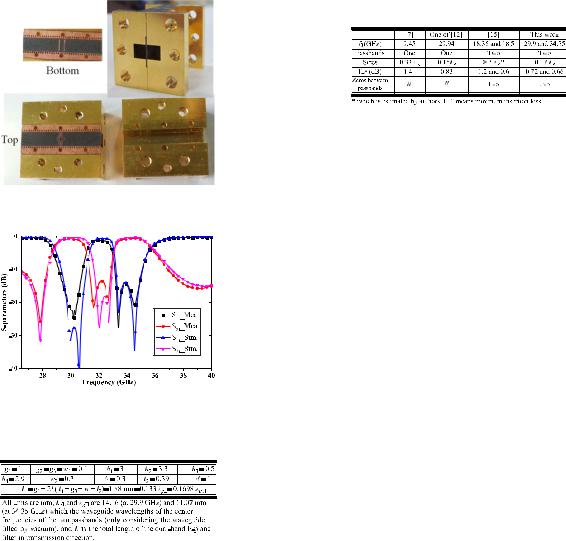
Fig. 5. The photograph of the broadband filter.
In this paper, a novel dual-band waveguide E-plane filter using three pairs of E-plane resonators has been designed and analyzed. Each pair of the resonators is arranged face-to- face. Two pairs are on the top side of the substrate and the remaining one pair of straight stripline resonators is etched at the bottom side. A sample has been fabricated and tested, whose total length in transmission direction is less than 0.14 λgL or 0.17 λgH. Two passbands with good filtering performance are obtained. The simulation results agree well with the measurement results. This dual-band E-plane filter with one insert has benefits of being inexpensive and having mass producible capabilities.
Fig. 6. The comparisons of simulation and measurement results.
TABLE I
DIMENSIONAL PARAMETERS
III. EXPERIMENTS OF THE PROPOSED FILTER
In this section, a sample of the proposed dual-band waveguide E-plane filter is fabricated and measured. A WR-28 cavity with a length of 20 mm is used for easy resembling and measurement. The Duriod 5880 substrate with three pairs of the resonators is inserted in the center E-plane of WR-28. The photograph is given in Fig. 5. This filter has been measured by PNA Network Analyzer E8361A. The comparisons of the simulation and measurement results are illustrated in Fig. 6. Good agreement between the simulation and measurement results is achieved. The first passband operates at 29.9 GHz with a 3 dBbandwidth of 7.4 % and the measured minimum insertion loss is 0.72 dB. And the second passband has a central frequency of 34.35 GHz with a 7.3 % 3dB-bandwidth and the measured minimum insertion loss is 0.66 dB. Two transmission zeroes are obviously measured between the two passbands to suppress the interferences. The parameters of the filter (except lengths of the input and output waveguide) are given in Table I and its total length in transmission direction is less than 0.14 λgL or 0.17 λgH. Some comparisons are illustrated in Table II. The designed dual-band filter with similar sizes of the single-band filter, has the dual-band operation. Compared with the dualmode cavity waveguide filter [15] with complex structures, our filter obtains a very large size reduction.
REFERENCES
[1]G. Cheng, S. Xiaobang, M. J. Lancaster, and X. Jun, “A 3-D printed lightweight X-band waveguide filter based on spherical resonators,” IEEE Microw. Wireless Compon. Lett., vol. 25, no. 7, pp. 442–444, Jul. 2015.
[2]L. Szydlowski and M. Mrozowski, “A self-equalized waveguide filter with frequency-dependent (resonant) couplings,” IEEE Microw. Wireless Compon. Lett., vol. 24, no. 11, pp. 769–771, Nov. 2014.
[3]Y. Konishi and K. Uenakada, “The design of a bandpass filter with inductive strip—Planar circuit mounted in waveguide,” IEEE Trans. Microw. Theory Techn., vol. 22, no. 10, pp. 869–873, Oct. 1974.
[4]Y. Y. Yang and X. H. Yin, “The analysis of the parameters and the functions of rectangular waveguide E-plane filter,” J. Infrared Millim. Terahertz Waves, vol. 30, no. 11, pp. 1161–1169, Nov. 2009.
[5]C. R. Dai, L. Hao, S. H. Bo, and H. J. Sun, “Parallel coupled microstrip and E-plane metal insert waveguide band-pass filter at W-band,” in Proc. Asia-Pacific Antennas Propag. Conf., 2014, pp. 1231–1233.
[6]Z. B. Xu, J. Guo, C. Qian, and W. B. Dou, “Broad-band E-plane filters with iImproved stop-band performance,” IEEE Microw. Wireless Compon. Lett., vol. 21, no. 7, pp. 350–352, Jul. 2011.
[7]N. Mohottige, O. Glubokov, and D. Budimir, “Ultra compact inline E-plane waveguide extracted pole bandpass filters,” IEEE Microw. Wireless Compon. Lett., vol. 23, no. 8, pp. 409–411, Aug. 2013.
[8]E. Ofli, R. Vahldieck, and S. Amari, “Novel E-plane filters and diplexers with elliptic response for millimeter-wave applications,” IEEE Trans. Microw. Theory Techn., vol. 53, no. 3, pp. 843–851, Mar. 2005.
[9]O. Glubokov and D. Budimir, “Compact filters using metal-dielectric inserts,” in Proc. IEEE 42nd Eur. Microw. Conf., 2012, pp. 1103–1106.
[10]N. Suntheralingam and D. Budimir, “Enhanced waveguide bandpass filters using S-shaped resonators,” Int. J. RF Microw. Comput.-Aided Eng., vol. 19, no. 6, pp. 627–633, Nov. 2009.
[11]O. Glubokov and D. Budimir, “Extraction of generalized coupling coefficients for inline extracted pole filters with nonresonating nodes,”
IEEE Trans. Microw. Theory Techn., vol. 59, no. 12, pp. 3023–3029, Dec. 2011.
[12]J. Y. Jin, X. Q. Lin, Y. Jiang, and Q. Xue, “A novel compact E-plane waveguide filter with multiple transmission zeroes,” IEEE Trans. Microw. Theory Techn., vol. 63, no. 10, pp. 3374–3380, Oct. 2015.
[13]J. Y. Jin and Q. Xue, “A type of E-plane filter using folded split ring resonators (FSRRs),” in Proc. Asia-Pacific Microw. Conf., 2015, pp. 1–3.
[14]S. Amari and M. Bekheit, “A new class of dual-mode dual-band waveguide filters,” IEEE Trans. Microw. Theory Techn., vol. 56, no. 8, pp. 1938–1944, Aug. 2008.
[15]P. Lenoir, S. Bila, F. Seyfert, D. Baillargeat, and S. Verdeyme, “Synthesis and design of asymmetrical dual-band bandpass filters based on equivalent network simplification,” IEEE Trans. Microw. Theory Techn., vol. 54, no. 7, pp. 3090–3097, Jul. 2006.