

диафрагмированные волноводные фильтры / 2fb6bb1f-b73f-464b-bb4a-f78efd67023d
.pdfJ. Phys. D: Appl. Phys. 49 (2016) 325105 |
|
|
|
|
|
|
|
|
|
|
|
A Ž Ilić et al |
|||||||||||||||||||||||||||||||||||
|
|
|
|
|
|
|
|
|
|
|
|
|
|
|
|
|
|
|
|
|
|
|
|
|
|
|
|
|
|
|
|
|
|
|
|
|
|
|
|
|
|
|
|
|
|
|
|
|
|
|
|
|
|
|
|
|
|
|
|
|
|
|
|
|
|
|
|
|
|
|
|
|
|
|
|
|
|
|
|
|
|
|
|
|
|
|
|
|
|
|
|
|
|
|
|
|
|
|
|
|
|
|
|
|
|
|
|
|
|
|
|
|
|
|
|
|
|
|
|
|
|
|
|
|
|
|
|
|
|
|
|
|
|
|
|
|
|
|
|
|
|
|
|
|
|
|
|
|
|
|
|
|
|
|
|
|
|
|
|
|
|
|
|
|
|
|
|
|
|
|
|
|
|
|
|
|
|
|
|
|
|
|
|
|
|
|
|
|
|
|
|
|
|
|
|
|
|
|
|
|
|
|
|
|
|
|
|
|
|
|
|
|
|
|
|
|
|
|
|
|
|
|
|
|
|
|
|
|
|
|
|
|
|
|
|
|
|
|
|
|
|
|
|
|
|
|
|
|
|
|
|
|
|
|
|
|
|
|
|
|
|
|
|
|
|
|
|
|
|
|
|
|
|
|
|
|
|
|
|
|
|
|
|
|
|
|
|
|
|
|
|
|
|
|
|
|
|
|
|
|
|
|
|
|
|
|
|
|
|
|
|
|
|
|
|
|
|
|
|
|
|
|
|
|
|
|
|
|
|
|
|
|
|
|
|
|
|
|
|
|
|
|
|
|
|
|
|
|
|
|
|
|
|
|
|
|
|
|
|
|
|
|
|
|
|
|
|
|
|
|
|
|
|
|
|
|
|
|
|
|
|
|
|
|
|
|
|
|
|
|
|
|
|
|
|
|
|
|
|
|
|
|
|
|
|
|
|
|
|
|
|
|
|
|
|
|
|
|
|
|
|
|
|
|
|
|
|
|
|
|
|
|
|
|
|
|
|
|
|
|
|
|
|
|
|
|
|
|
|
|
|
|
|
|
|
|
|
|
|
|
|
|
|
|
|
|
|
|
|
|
|
|
|
|
|
|
|
|
|
|
|
|
|
|
|
|
|
|
|
|
|
|
|
|
|
|
|
|
|
|
|
|
|
|
|
|
|
|
|
|
|
|
|
|
|
|
|
|
|
|
|
|
|
|
|
|
|
|
|
|
|
|
|
|
|
|
|
|
|
|
|
|
|
|
|
|
|
|
|
|
|
|
|
|
|
|
|
|
|
|
|
|
|
|
|
|
|
|
|
|
|
|
|
|
|
|
|
|
|
|
|
|
|
|
|
|
|
|
|
|
|
|
|
|
|
|
|
|
|
|
|
|
|
|
|
|
|
|
|
|
|
|
|
|
|
|
|
|
|
|
|
|
|
Figure 6. Graphene–metal combined waveguide resonators (WR-2.2 section). Graphene stripes are located along the inner edges of the E-plane inserts. (a) Effect of varying graphene stripe widths on tunability, insertion loss and quality factor of a resonator. A graphene percentage larger than 50% of an insert does not notably improve tunability; however, it worsens the quality factor. (b) Effect of the E-plane insert length on quality factor and losses in graphene for the fixed width of the graphene stripe, lG = 80 µm. (c) Effect of the E-plane insert length on the quality factor and insertion loss for the fixed width lG = 50 µm. Curves corresponding to the all-metal resonators are given by
the golden dash–dot–dot lines ( f Mrez 480 GHz). (a) lT = 0.324a, (b) lG = 80 µm, (c) lG = 50 µm.
Table 3. Dependence of resonator properties on the width of graphene stripes (fixed total inserts length)a.
pg = |
lG |
(%) |
b |
Tp = |
frez |
|
0.4 eV |
|
1.0 eV |
|
0.4 eV |
1.0 eV |
|
frez (GHz) |
|
(%) |
IL |
(dB) |
IL |
(dB) |
QL |
QL |
|||
lT |
f M |
|||||||||||
|
|
|
|
|
rez |
|
|
|
|
|
|
|
|
|
|
|
|
|
|
|
|
|
|
|
|
100.0 |
|
|
28.25 |
5.89 |
|
|
2.03 |
|
1.82 |
|
4.92 |
11.75 |
75.0 |
|
|
27.50 |
5.74 |
|
|
3.03 |
|
2.18 |
|
13.50 |
17.12 |
50.0 |
|
|
22.50 |
4.69 |
|
|
2.84 |
|
2.09 |
|
17.71 |
19.44 |
25.0 |
|
|
13.50 |
2.82 |
|
|
1.87 |
|
1.62 |
|
22.21 |
22.06 |
12.5 |
|
|
6.25 |
1.30 |
|
|
1.05 |
|
1.08 |
|
24.73 |
23.48 |
aData is obtained for the standard WR-2.2 waveguide section, with lrez = 210.0 µm and lT = 181.2 µm.
bChemical potential of graphene, µc, has been varied in the range (0.4–1.0) eV.
considered frequencies, the loaded quality factor declines significantly for the lower values of the graphene chemical potential. The loaded quality factor is calculated as QL = frez /BW3 dB, with BW3 dB denoting the 3 dB bandwidth of the S21 parameter. The graphene-on-quartz resonators are, in any case, characterized by the notably lower loaded quality factors than their pure metallic counterparts, and this is particularly pronounced for the lower chemical potential and larger impedances. Increase in the graphene surface impedance produces effects similar to the effects of varying the effective resonator length by changing the distance, lrez, between the E-plane inserts. The same holds for the total length of the E-plane insert which appears effectively shorter and leads to the decline in the resonator quality factor. We address this issue by introducing the graphene–metal combined waveguide resonators. The graphene stripes are now located along the inner edges of the E-plane inserts, at the lrez side, whereas the remaining parts of the inserts are covered by the Cu or Au thin film. Such a configuration is expected to have less influence on the resonator quality factor; however, the decrease in tunability is also expected and has to be investigated.
The concept of the graphene–metal combined waveguide resonators is presented in figure 6, using the WR-2.2 waveguide section with the resonator length lrez = 210 µm. The ratio lT/ a is varied as denoted in the figures. The S21-parameter curves for the purely metallic resonators of the same sizes are denoted using the dash–dot–dot lines, with the resonant frequencies at about 480 GHz. In figure 6(a) we investigate the
effect on the resonator parameters of the width of the graphene stripe, expressed as the percentage graphene with respect to the E-plane insert length. To keep the graph less complicated, for each of the five compared graphene stripe widths, we only show the S21-parameter for µc = 0.4 eV and µc = 1.0 eV. Each pair of lines corresponding to the same percent of graphene, pg, is presented in distinctive color (shade of gray) in different line style. For better legibility, the data shown in figure 6(a) is also summarized in table 3.
As can be concluded from figure 6(a) as well as table 3, a graphene percentage larger than 50% does not further improve the tunability; however, the quality factor decreases and the loss increases. Therefore, less than half of an insert could be covered by graphene. Please note, that the tunability range presented in table 3 differs from the one used throughout the paper due to the use of the (0.4–1.0) eV range for the chemical potential. There already is a significant quality factor deterioration for µc = 0.4 eV, in comparison with the one for µc = 1.0 eV, with the increase in the graphene stripe width. This is even more pronounced for µc (0.2–1.0) eV, whereas the tunability is approximately doubled.
As can be inferred from the above observations, the gra- phene–metal combined waveguide resonators can be carefully designed to meet the specific design requirements. Adjustment of the design parameters starts with the choice of the graphene stripe width, lG, in accordance with the desired tunability range. This is illustrated by choosing lG = 80 µm for the figure 6(b) and lG = 50 µm for the figure 6(c). After
10

J. Phys. D: Appl. Phys. 49 (2016) 325105 |
A Ž Ilić et al |
|
|
Table 4. Dependence of resonator properties on the total length of an E-plane inserta.
E-plane insert length |
b |
|
= |
frez |
(%) |
|
0.2 eV |
(dB) |
|
1.0 eV |
(dB) |
|
0.2 eV |
1.0 eV |
|
M |
|
f (GHz) |
T |
|
IL |
|
IL |
|
Q |
L |
Q |
L |
Q |
L |
|||||
f M |
|
|
|||||||||||||||
|
rez |
p |
|
|
|
|
|
|
|
|
|
|
|
||||
|
|
|
|
rez |
|
|
|
|
|
|
|
|
|
|
|
|
|
|
|
|
|
|
|
|
|
|
|
||||||||
|
|
Graphene stripe width lG = 80 µm |
|
|
|
|
|
|
|
||||||||
lT = 0.26a |
39.75 |
8.29 |
|
|
1.71 |
|
1.34 |
|
11.68 |
12.62 |
15.56 |
||||||
lT = 0.34a |
38.00 |
7.92 |
|
|
3.01 |
|
2.22 |
|
21.55 |
21.82 |
25.91 |
||||||
lT = 0.42a |
36.75 |
7.66 |
|
|
5.01 |
|
3.55 |
|
34.58 |
34.75 |
42.44 |
||||||
lT = 0.50a |
36.50 |
7.61 |
|
|
7.87 |
|
5.45 |
|
47.43 |
50.17 |
70.59 |
||||||
|
|
Graphene stripe width lG = 50 µm |
|
|
|
|
|
|
|
||||||||
|
|
|
|
|
|
|
|
|
|
|
|
||||||
lT = 0.26a |
26.00 |
5.42 |
|
|
1.19 |
|
1.12 |
|
14.40 |
13.77 |
15.56 |
||||||
lT = 0.34a |
25.00 |
5.21 |
|
|
2.09 |
|
1.91 |
|
26.17 |
24.04 |
25.91 |
||||||
lT = 0.42a |
24.75 |
5.16 |
|
|
3.54 |
|
3.07 |
|
42.10 |
38.02 |
42.44 |
||||||
lT = 0.50a |
23.75 |
4.95 |
|
|
5.55 |
|
4.64 |
|
63.93 |
55.18 |
70.59 |
||||||
aData is obtained for the standard WR-2.2 waveguide section, with lrez = 210.0 µm and a = 2b = 559.0 µm.
bChemical potential of graphene, µc, has been varied in the range (0.2–1.0) eV.
Figure 7. EM field distribution along the E-plane insert for various widths of the graphene stripe. Graphene–metal combined waveguide resonators comply with equations (16a) and (16b), along the given percentage of an E-plane insert covered by graphene. In the metallic part of an insert, Ey approaches zero. Due to the differences of the structures considered in (a)–(d), and thus the field distributions, the relative impact of the variations in graphene surface impedance is larger for the smaller graphene percentage. (a) pg = 100%, (b) pg = 50%,
(c) pg = 25%, (d) pg = 12.5%.
that, the tunability remains almost the same for different total insert lengths, lT. Optimizing a trade-off between the quality factor and the loss is the next step, in which the total E-plane insert length, lT, is defined. With the increase of lT, both the quality factor and the insertion loss increase. Relevant data for these two cases is summarized in table 4. We can conclude from table 4 that the obtained tunability percentages Tp (cal-
culated very strictly, i.e. with respect to f Mrez, which is always well above the device tunable bandwidth), in the considered examples range from around 5% to higher than 8%. Noting that a wide tunability range is hard to obtain in submillimeter applications, and that even better tunability can be achieved using stripe widths wider than 80 µm, the reported tunability percentages are on the same order of magnitude as those in the state-of-the-art receivers [45], where several receivers are employed to cover a wider submillimeter bandwidth.
Reasons for the higher insertion loss of the graphene–metal combined waveguide resonators, in comparison with the initially analyzed graphene-on-quartz resonators, stem from the different boundary conditions at the E-plane inserts. Different boundary conditions mandate different EM field distribution in the vicinity of the inserts, as well as in the graphene stripe.
Along the part of an E-plane insert covered by graphene, EM field complies with equations (16a) and (16b), whereas in the metallic part of an insert the field vanishes. For a narrow graphene stripe and a longer metallic part of an insert, a stronger field is generated. Simulation results for different graphene percentages, pg, are presented in figure 7.
Dependence of the tunability, quality factor, and insertion loss on the graphene percentage, illustrated in figure 6(a), has been studied in detail taking the values from zero to pg = 100%, with the step of 2.5%, as an input parameter. The results are presented in figure 8. For the relatively narrow graphene stripes, with pg 20%, the loaded quality factor remains close to the one corresponding to purely metallic inserts, QML = 42.44. At the same time, insertion loss is low and varies only slightly for the considered graphene chemical potential interval from 0.2 to 1.0 eV. Tunability of up to 5% can be achieved. These results agree with the third row describing the lG = 50 µm case in table 4, where pg = 21.3%. At about 50% graphene coverage of an insert, 10% tunability can be expected with the still very good quality factor of about 70% of QML . In this case loss is the highest. According to figure 8,
11
J. Phys. D: Appl. Phys. 49 (2016) 325105 |
|
|
|
|
|
|
|
|
|
|
|
|
|
|
|
|
|
|
|
|
|
|
|
|
|
|
|
|
|
|
|
|
|
|
|
|
|
|
|
|
|
|
|
|
A Ž Ilić et al |
||||||||||||||||||||||||||
|
|
|
|
|
|
|
|
|
|
|
|
|
|
|
|
|
|
|
|
|
|
|
|
|
|
|
|
|
|
|
|
|
|
|
|
|
|
|
|
|
|
|
|
|
|
|
|
|
|
|
|
|
|
|
|
|
|
|
|
|
|
|
|
|
|
|
|
|
|
|
|
|
|
|
|
|
|
|
|
|
|
|
|
|
|
|
|
|
|
|
|
|
|
|
|
|
|
|
|
|
|
|
|
|
|
|
|
|
|
|
|
|
|
|
|
|
|
|
|
|
|
|
|
|
|
|
|
|
|
|
|
|
|
|
|
|
|
|
|
|
|
|
|
|
|
|
|
|
|
|
|
|
|
|
|
|
|
|
|
|
|
|
|
|
|
|
|
|
|
|
|
|
|
|
|
|
|
|
|
|
|
|
|
|
|
|
|
|
|
|
|
|
|
|
|
|
|
|
|
|
|
|
|
|
|
|
|
|
|
|
|
|
|
|
|
|
|
|
|
|
|
|
|
|
|
|
|
|
|
|
|
|
|
|
|
|
|
|
|
|
|
|
|
|
|
|
|
|
|
|
|
|
|
|
|
|
|
|
|
|
|
|
|
|
|
|
|
|
|
|
|
|
|
|
|
|
|
|
|
|
|
|
|
|
|
|
|
|
|
|
|
|
|
|
|
|
|
|
|
|
|
|
|
|
|
|
|
|
|
|
|
|
|
|
|
|
|
|
|
|
|
|
|
|
|
|
|
|
|
|
|
|
|
|
|
|
|
|
|
|
|
|
|
|
|
|
|
|
|
|
|
|
|
|
|
|
|
|
|
|
|
|
|
|
|
|
|
|
|
|
|
|
|
|
|
|
|
|
|
|
|
|
|
|
|
|
|
|
|
|
|
|
|
|
|
|
|
|
|
|
|
|
|
|
|
|
|
|
|
|
|
|
|
|
|
|
|
|
|
|
|
|
|
|
|
|
|
|
|
|
|
|
|
|
|
|
|
|
|
|
|
|
|
|
|
|
|
|
|
|
|
|
|
|
|
|
|
|
|
|
|
|
|
|
|
|
|
|
|
|
|
|
|
|
|
|
|
|
|
|
|
|
|
|
|
|
|
|
|
|
|
|
|
|
|
|
|
|
|
|
|
|
|
|
|
|
|
|
|
|
|
|
|
|
|
|
|
|
|
|
|
|
|
|
|
|
|
|
|
|
|
|
|
|
|
|
|
|
|
|
|
|
|
|
|
|
|
|
|
|
|
|
|
|
|
|
|
|
|
|
|
|
|
|
|
|
|
|
|
|
|
|
|
|
|
|
|
|
|
|
|
|
|
|
|
|
|
|
|
|
|
|
|
|
|
|
|
|
|
|
|
|
|
|
|
|
|
|
|
|
|
|
|
|
|
|
|
|
|
|
|
|
|
|
|
|
|
|
|
|
|
|
|
|
|
|
|
|
|
|
|
|
|
|
|
|
|
|
|
|
|
|
|
|
|
|
|
|
|
|
|
|
|
|
|
|
|
|
|
|
|
|
|
|
|
|
|
|
|
|
|
|
|
|
|
|
|
|
|
|
|
|
|
|
|
|
|
|
|
|
|
|
|
|
|
|
|
|
|
|
|
|
|
|
|
|
|
|
|
|
|
|
|
|
|
|
|
|
|
|
|
|
|
|
|
|
|
|
|
|
|
|
|
|
|
|
|
|
|
|
|
|
|
|
|
|
|
|
|
|
|
|
|
|
|
|
|
|
|
|
|
|
|
|
|
|
|
|
|
|
|
|
|
|
|
|
|
|
|
|
|
|
|
|
|
|
|
|
|
|
|
|
|
|
|
|
|
|
|
|
|
|
|
|
|
|
|
|
|
|
|
|
|
|
|
|
|
|
|
|
|
|
|
|
|
|
|
|
|
|
|
|
|
|
|
|
|
|
|
|
|
|
|
|
|
|
|
|
|
|
|
|
|
|
|
|
|
|
|
|
|
|
|
|
|
|
|
|
|
|
|
|
|
|
|
|
|
|
|
|
|
|
|
|
|
|
|
|
|
|
|
|
|
|
|
|
|
|
|
|
|
|
|
|
|
|
|
|
|
|
|
|
|
|
|
|
|
|
|
|
|
|
|
|
|
|
|
|
|
|
|
|
|
|
|
|
|
|
|
|
|
|
|
|
|
|
|
|
|
|
|
|
|
|
|
|
|
|
|
|
|
|
|
|
|
|
|
|
|
|
|
|
|
|
|
|
|
|
|
|
|
|
|
|
|
|
|
|
|
|
|
|
|
|
|
|
|
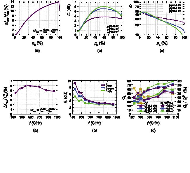
Figure 8. Detailed analysis of the dependence of (a) tunability range, (b) insertion loss, and (c) loaded quality factor, on the width of the graphene stripe expressed as the percentage of the E-plane insert length. WR-2.2 waveguide section with lrez = 210 µm and lT = 0.42a has been used for this analysis. Data is presented for the three values of graphene chemical potential, as denoted in the legend. The design of the graphene–metal combined waveguide resonators is subject to the trade-off between the tunability, quality factor, and loss. Optimal width of the graphene stripe is from 15% to about 40% of the E-plane insert length.
Figure 9. Comparative analysis of the (a) tunability range, (b) insertion loss, and (c) loaded quality factor, for the graphene–metal
combined waveguide resonators covering the frequency range from 100 to 1100 GHz. Frequency points correspond to the f Mrez of the
considered waveguide section. Reasonable tunability of 5–6% was obtained in all frequency intervals (a). Loss, calculated using the interval from 0.2 to 1.0 eV for µc, is somewhat higher than in the graphene-on-quartz case and should be compensated in the design (b). Absolute values of the loaded quality factor, including the pure metallic resonators of the given sizes, are shown in (c) by the filled squares and the
solid lines. Quality factors of the combined resonators are shown as the percentage of QML, using the empty squares and the dashed lines.
Table 5. Graphene–metal combined waveguide resonators: considered dimensions and resonant frequencies.
EIA/Ext. MIL |
lrez (µm) |
lT (µm) |
f Mrez (GHz) |
f 0.2rez eV (GHz) |
f 0.4rez eV (GHz) |
f 1.0rezeV (GHz) |
WR-6 |
720.0 |
693.4 |
154.75 |
144.50 |
148.25 |
151.25 |
WR-4 |
420.0 |
458.7 |
243.25 |
222.50 |
228.75 |
235.50 |
WR-3 |
360.0 |
362.7 |
299.75 |
273.00 |
280.50 |
289.25 |
WR-2.8 |
260.0 |
298.7 |
378.75 |
340.00 |
350.00 |
362.25 |
WR-2.2 |
210.0 |
234.7 |
477.50 |
426.00 |
438.00 |
454.25 |
WR-1.5 |
146.0 |
160.0 |
697.50 |
614.50 |
629.50 |
653.75 |
WR-1.2 |
132.0 |
128.0 |
838.50 |
742.50 |
758.00 |
784.00 |
WR-1.0 |
104.0 |
106.7 |
1028.25 |
900.50 |
917.50 |
949.50 |
|
|
|
|
|
|
|
the optimal width of the graphene stripe is from about 15% to approximately 40%, where the quality factor is high and consistent throughout the achieved tunability range.
Frequency dependence of the key representative para meters of the graphene–metal combined waveguide resonators is given in figure 9. We again analyze the graphene-based waveguide resonators corresponding to the WR-6, WR-4, WR-3, WR-2.8, WR-2.2, WR-1.5, WR-1.2, and WR-1.0 waveguides. Resonator length has been kept the same as in the previous analyses; it is listed in table 5, along with
the chosen insert length, lT = 0.42a. Quartz thickness is d = a/16, whereas the graphene stripe width is kept at 25% of an E-plane insert length in all the analyses. Resonant frequencies are listed in table 5, whereas the other results are shown in figure 9. There is a significant decrease of the insertion loss with frequency in the investigated frequency range. Quality factors at higher frequencies are excellent, represented in comparison with the QML. Tunability range in between 5% and 6% is obtained with the graphene–metal combined waveguide resonators, supporting the proposed concept as one of
12
J. Phys. D: Appl. Phys. 49 (2016) 325105 |
A Ž Ilić et al |
|
|
the possible solutions for the millimeter and submillimeter wave applications.
4. Conclusion
A novel concept of tunable waveguide resonators for submillimeter wave applications has been studied in detail, following our promising preliminary investigation of WR-3 waveguide. Theoretical analysis has been presented, which could be used to develop customized software tools for the design of this type of waveguide resonator. Thorough full-wave numerical simulations covering several waveguide sections and frequencies ranging from 100 to 1100 GHz confirmed the possibility of obtaining 5% tunability with excellently preserved resonator loaded quality factors, as well as larger tunability ranges, where the trade-off with quality factor and insertion loss is carried out. Tunable waveguide resonators are important basic building blocks of tunable filter devices, and the proposed concept is of great significance for the development of the compact and flexible components in the submillimeter wave spectral region.
Acknowledgments
This work was supported by the Serbian Ministry of Education, Science, and Technological Development under grant III-45003 and in part by the EU—Erasmus Mundus Action 2 project EUROWEB.
References
[1]Zmuidzinas J and Richards P L 2004 Superconducting
detectors and mixers for millimeter and submillimeter astrophysics Proc. IEEE 92 1597–616
[2]Appleby R and Anderton R N 2007 Millimeter-wave and
submillimeter-wave imaging for security and surveillance
Proc. IEEE 95 1683–90
[3]Globus T R, Woolard D L, Samuels A C, Gelmont B L, Hesler J, Crowe T W and Bykhovskaia M 2002
Submillimeter-wave Fourier transform spectroscopy of biological macromolecules J. Appl. Phys. 91 6105–13
[4]Garcı́a-Garcı́a J, Martı́n F, Miles R E, Steenson D P, Chamberlain J M, Fletcher J R and Thorpe J R 2002 Parametric analysis of micromachined reflex klystrons for
operation at millimeter and submillimeter wavelengths
J. Appl. Phys. 92 6900–4
[5]Song H-J and Nagatsuma T 2011 Present and future of
terahertz communications IEEE Trans. Terahertz Sci. Technol. 1 256–63
[6]Shang X, Ke M, Wang Y and Lancaster M J 2012 WR-3 band waveguides and filters fabricated using SU8 photoresist
micromachining technology IEEE Trans. Terahertz Sci. Technol. 2 629–37
[7]Chen Z, Zheng Y, Kang X, Lu B and Cui B 2013 WR-2.8 band
micromachined rectangular waveguide filter J. Infrared Millim. Terahertz Waves 34 847–55
[8]Samoska L A 2011 An overview of solid-state integrated
circuit amplifiers in the submillimeter-wave and THz regime IEEE Trans. Terahertz Sci. Technol. 1 9–24
[9]Tamagnone M, Gomez-Diaz J S, Mosig J R and PerruisseauCarrier J 2012 Reconfigurable terahertz plasmonic
antenna concept using a graphene stack Appl. Phys. Lett.
101214102
[10]Dragoman M, Muller A A, Dragoman D, Coccetti F and Plana R 2010 Terahertz antenna based on graphene J. Appl. Phys. 107 104313
[11]Mencarelli D, Bellucci S, Sindona A and Pierantoni L 2015 Spatial dispersion effects upon local excitation of extrinsic plasmons in a graphene micro-disk J. Phys. D: Appl. Phys.
48465104
[12]Sensale-Rodriguez B, Yan R, Kelly M M, Fang T, Tahy K, Hwang W S, Jena D, Liu L and Xing H G 2012 Broadband graphene terahertz modulators enabled by intraband transitions Nat. Commun. 3 780
[13]Li H-J, Wang L-L, Sun B, Huang Z-R and Zhai X 2014 Tunable mid-infrared plasmonic band-pass filter based on a single graphene sheet with cavities J. Appl. Phys.
116224505
[14]Otsuji T, Boubanga Tombet S A, Satou A, Fukidome H, Suemitsu M, Sano E, Popov V, Ryzhii M and Ryzhii V 2012 Graphene-based devices in terahertz science and technology J. Phys. D: Appl. Phys. 45 303001
[15]Carrasco E, Tamagnone M and Perruisseau-Carrier J 2013 Tunable graphene reflective cells for THz reflectarrays and generalized law of reflection Appl. Phys. Lett.
102104103
[16]Gomez-Diaz J S, Perruisseau-Carrier J, Sharma P and Ionescu A 2012 Non-contact characterization of graphene surface impedance at micro and millimeter waves J. Appl. Phys. 111 114908
[17]Hanson G W 2008 Dyadic Green’s functions and guided surface waves for a surface conductivity model of graphene
J. Appl. Phys. 103 064302
[18]Ilić A Ž and Budimir D 2014 Electromagnetic analysis of
graphene based tunable waveguide resonators Microw. Opt. Technol. Lett. 56 2385–8
[19]Ridler N M and Ginley R A 2011 IEEE P1785: a new standard for waveguide above 110 GHz Microw. J. 54 S20–4
[20]Hesler J L, Kerr A R, Grammer W and Wollack E 2007 Proc.
18th Int. Symp. on Space Terahertz Technology (Pasadena, CA, 21–23 March 2007) ed A Karpov (Pasadena: Caltech) pp 100–3
[21]Postoyalko V and Budimir D S 1994 Design of waveguide
E-plane filters with all-metal inserts by equal ripple optimization IEEE Trans. Microw. Theory Tech. 42 217–22
[22]Kolundzija B and Djordjevic A 2002 Electromagnetic Modeling of Composite Metallic and Dielectric Structures
(Norwood, MA: Artech House) (WIPL-D 2013 WIPL-D Pro v11.0 Available: http://wipl-d.com/)
[23]ANSYS HFSS Available: http://ansys.com
[24]Collin R E 1991 Field Theory of Guided Waves (Piscataway, NJ: IEEE)
[25]Konishi Y and Uenakada K 1974 The design of a bandpass filter with inductive strip—planar circuit mounted in waveguide IEEE Trans. Microw. Theory Tech. 22 869–73
[26]Arndt F, Bornemann J, Grauerholz D and Vahldieck R 1982
Theory and design of low-insertion loss fin-line filters IEEE Trans. Microw. Theory Tech. 30 155–63
[27]Lovat G 2012 Equivalent circuit for electromagnetic
interaction and transmission through graphene sheets IEEE Trans. Electromagn. Compat. 54 101–9
[28]Svintsov D, Vyurkov V, Orlikovsky A, Ryzhii V and Otsuji T 2014 All-graphene field-effect transistor based on lateral tunnelling J. Phys. D: Appl. Phys. 47 094002
[29]Gomez-Diaz J S, Moldovan C, Capdevila S, Romeu J, Bernard L S, Magrez A, Ionescu A M and PerruisseauCarrier J 2015 Self-biased reconfigurable graphene stacks for terahertz plasmonics Nat. Commun. 6 6334
[30]Liu M, Yin X and Zhang X 2012 Double-layer graphene optical modulator Nano Lett. 12 1482–5
13
J. Phys. D: Appl. Phys. 49 (2016) 325105 |
A Ž Ilić et al |
|
|
[31]Reina A, Jia X, Ho J, Nezich D, Son H, Bulovic V, Dresselhaus M S and Kong J 2009 Large area, few-layer
graphene films on arbitrary substrates by chemical vapor deposition Nano Lett. 9 30–5
[32]Wei D, Mitchell J I, Tansarawiput C, Nam W, Qi M, Ye P D
and Xu X 2013 Laser direct synthesis of graphene on quartz
Carbon 53 374–9
[33]Vianco P T, Sifford C H and Romero J A 1997 Resistivity
and adhesive strength of thin film metallizations on single crystal quartz IEEE Trans. Ultrason. Ferroelectr. Freq. Control 44 237–49
[34]Lee S M and Krim J 2005 Scanning tunneling microscopy characterization of the surface morphology of copper
films grown on mica and quartz Thin Solid Films 489 325–9
[35]Neugebauer P, Orlita M, Faugeras C, Barra A-L and Potemski M 2009 How perfect can graphene be? Phys. Rev. Lett. 103 136403
[36]Jablan M, Buljan H and Soljačić M 2009 Plasmonics in graphene at infra-red frequencies Phys. Rev. B
80 245435
[37]Bolotin K I, Sikes K J, Jiang Z, Klima M, Fudenberg G, Hone J, Kim P and Stormer H L 2008 Ultrahigh electron
mobility in suspended graphene Solid State Commun. 146 351–5
[38]Bolotin K I, Sikes K J, Hone J, Stormer H L and Kim P 2008 Temperature-dependent transport in suspended graphene
Phys. Rev. Lett. 101 096802
[39]Hirai H, Tsuchiya H, Kamakura Y, Mori N and Ogawa M 2014 Electron mobility calculation for graphene on substrates J. Appl. Phys. 116 083703
[40]Mayorov A S et al 2011 Micrometer-scale ballistic transport
in encapsulated graphene at room temperature Nano Lett. 11 2396–9
[41]Varchon F, Feng R, Hass J, Li X, Ngoc Nguyen B, Naud C, Mallet P, Veuillen J-Y, Berger C, Conrad E H and Magaud L 2007 Electronic structure of epitaxial graphene layers on SiC: effect of the substrate Phys. Rev. Lett. 99 126805
[42]Orlita M et al 2008 Approaching the dirac point in highmobility multilayer epitaxial graphene Phys. Rev. Lett. 101 267601
[43]Forti S and Starke U 2014 Epitaxial graphene on SiC: from carrier density engineering to quasi-free standing graphene by atomic intercalation J. Phys. D: Appl. Phys. 47 094013
[44]Ryzhii V, Dubinov A A, Otsuji T, Mitin V and Shur M S
2010 Terahertz lasers based on optically pumped multiple graphene structures with slot-line and dielectric waveguides
J. Appl. Phys. 107 054505
[45]de Graauw Th et al 2010 The Herschel-heterodyne instrument for the far-infrared (HIFI) Astron. Astrophys. 518 L6
14