

диафрагмированные волноводные фильтры / f34742a3-7dd9-4872-ad17-89c7cb24b29b
.pdfIEEE MICROWAVE AND WIRELESS COMPONENTS LETTERS, VOL. 23, NO. 8, AUGUST 2013 |
409 |
Ultra Compact Inline  -Plane Waveguide
Extracted Pole Bandpass Filters
N. Mohottige, Student Member, IEEE, O. Glubokov, Member, IEEE, and D. Budimir, Senior Member, IEEE
Abstract—This letter presents an ultra compact extracted pole  -plane filter. The proposed structure can achieve up to 65% size reduction in comparison with a standard extracted pole filter designed at 9.5 GHz centre frequency with a 3% fractional bandwidth. The filter has been fabricated and tested using
  -plane waveguide technology. Measurements on a fabricated filter confirm the accuracy of the design method.
Index Terms— -plane filters, extracted pole filters, inline filters, waveguide filters.
WAVEGUIDE filters offer a unique set of benefits for modern microwave and millimetre-wave applications in terms of low-loss and high power handling capability. How-
ever, current advancements in mobile communication systems have placed stringent demands for compactness of these structures.
 -plane technology, well known for its low-cost and mass producible characteristics, was first introduced by Konishi and Uenakada [1] and has since become one of the most popular technologies for waveguide filters implementation. However, one of the disadvantages of
  -plane filters is their considerable size. One of the approaches that lead to size reduction is the miniaturization of resonators. Such attempts at achieving compactness for this type of structures were made using SRRs [2], S-shape resonators [3], and extracted pole sections (EPS)
[4].Another contribution to increase in size is partly due to the widths of septa required for realizing low coupling coefficients between adjacent resonators. The most recent development was the introduction of an EPS which has the capability of generating two poles and a transmission zero using a single section
[5].This greatly aided in improving lower stop band selectivity, however not much improvement towards compactness has been made. This letter therefore addresses this issue and proposes an ultra compact  -plane waveguide EPS filter for applications where space is at a premium.
II. EXTRACTED POLE SECTIONS
Let us consider an  -plane insert creating an EPS within a rectangular waveguide, shown in Fig. 1(a). The insert consists of
Manuscript received May 09, 2013; accepted May 22, 2013. Date of publication July 15, 2013; date of current version August 05, 2013.
D. Budimir is with the Wireless Communication Research Group, Faculty of Science and Technology, University of Westminster, London, W1W 6UW, U.K. (e-mail: d.budimir@wmin.ac.uk).
N. Mohottige and O. Glubokov are with the Wireless Communication Research Group, Electronics and Computer Science, University of Westminster, London, W1W 6UW, U.K.
Color versions of one or more of the figures in this letter are available online at http://ieeexplore.ieee.org.
Digital Object Identifier 10.1109/LMWC.2013.2270431
Fig. 1. Extracted pole sections: (a)  -plane waveguide insert for standard EPS; (b)
  -plane waveguide insert for ultra compact EPS; (c) Equivalent circuit model for ultra compact EPS; (d) Arrangement of
  -plane insert within waveguide housing.
input and output metallic septa, two uniform waveguide sections and a metallic rectangular fin with one end open and the other connected to the top ground plane. This structure is capable of producing a single pole and a single transmission zero at the upper stop band [4].
Extending length of EPS, the structure has shown to produce two poles and a single transmission zero at the lower stop band [5], however it sacrifices size as well as upper stop band performance in order to achieve this trait.
1531-1309/$31.00 © 2013 IEEE
410 |
IEEE MICROWAVE AND WIRELESS COMPONENTS LETTERS, VOL. 23, NO. 8, AUGUST 2013 |
This drawback can be overcome by the introduction of two extra fins as depicted in Fig. 1(b), which improves performance as well as achieve significant size reduction. Fig. 1(c) shows a schematic model of the proposed ultra compact filter, with the input/output septa represented by  inverters.
  -blocks represent fins as series LC resonators which are spaced through sections of transmission lines with phase length
  and characteristic impedance
 . The
. The 


 -matrix for a single extracted pole section (Fig. 1(a)) without septa can be computed as a system of cascaded 2-port networks
(1)
The initial over-all 


 -matrix of the entire ultra compact filter can be approximately obtained (without taking into consideration of the additional couplings, represented by dashed lines) as
|
|
|
|
|
|
|
|
|
|
|
|
|
|
|
|
|
|
|
|
|
|
|
|
|
|
|
|
|
|
|
|
|
|
|
|
|
|
|
|
|
|
|
|
|
|
|
|
|
|
|
|
|
|
|
|
|
|
|
|
|
|
|
|
|
|
|
|
|
|
|
|
|
|
|
|
|
|
|
|
|
|
|
|
|
|
|
|
|
|
|
|
|
|
|
|
|
|
|
|
|
|
|
|
|
|
|
|
|
|
|
|
|
|
|
|
|
|
|
|
|
|
|
|
|
|
|
|
where |
|
|
|
|
|
|
|
|
|
|
|
|
|
|
|
|
|
|
|
|
|
|
|
|
|
|
|
|
|
|
|
|
|
|
|
|
|
|
|
|
|
|
|
|
|
|
|
|
|
|
|
|
(2) |
||||||||||
|
|
|
|
|
|
|
|
|
|
|
|
|
|
|
|
|
|
|
|
|
|
|
|
|
|
|
|
|
|
|
|
|
|
|
|
|
|
|
|
|
|
|
|
|
|
|
|
|
|
|
|
||||||||||||
|
|
|
|
|
|
|
|
|
|
|
|
|
|
|
|
|
|
|
|
|
|
|
|
|
|
|
|
|
|
|
|
|
|
|
|
|
|
|
|
|
|
|
|
|
|
|
|
|
|
|
|
|
|
|
|
|
|
|
|
||||
|
|
|
|
|
|
|
|
|
|
|
|
|
|
|
|
|
|
|
|
|
|
|
|
|
|
|
|
|
|
|
|
|
|
|
|
|
|
|
|
|
|
|
|
|
|
|
|
|
|
|
|
|
|
|
|
|
|
|
|
||||
|
|
|
|
|
|
|
|
|
|
|
|
|
|
|
|
|
|
|
|
|
|
|
|
|
|
|
|
|
|
|
|
|
|
|
and |
|
|
|
|
|
|
|
|
|
represents |
||||||||||||||||||
|
|
|
|
|
|
|
|
|
|
|
|
|
|
|
|
|
|
|
|
|
|
|
|
|
|
|
|
|
|
|
|
|
|
|
|
|
|
|
|||||||||||||||||||||||||
angular frequency |
|
|
of the |
|
transmission |
|
zero |
generated by |
|
|
|
|
|
|
fin. |
||||||||||||||||||||||||||||||||||||||||||||||||
|
|
|
|
|
|
|
|
|
|||||||||||||||||||||||||||||||||||||||||||||||||||||||
The system is considered to be symmetric, hence |
|
|
|
|
|
|
|
|
. |
|
|
|
|
|
|
||||||||||||||||||||||||||||||||||||||||||||||||
|
|
|
|
|
|
|
|
|
|
|
|
|
|
||||||||||||||||||||||||||||||||||||||||||||||||||
|
|
To obtain poles of the structure, one applies |
|
|
|
|
|
|
|
|
|
|
|
|
to the |
||||||||||||||||||||||||||||||||||||||||||||||||
|
|
|
|
|
|
|
|
|
|
|
|
||||||||||||||||||||||||||||||||||||||||||||||||||||
input and output of the circuit. Therefore, the resonant condition
is |
|
|
|
|
|
|
|
and due to reciprocity, |
|
|
|
|
|
|
|
|
|
|
|
|
|
|
|
|
|
||||
|
|
|
|
|
|
|
|
|
|
|
|
|
|
|
|
|
|
|
|
|
|
|
|
||||||
|
|
|
|
|
|
|
|
|
|
|
|
|
|
|
|
|
|
|
|
|
|
|
|
|
|
|
|
|
|
|
|
|
|
|
|
|
|
|
|
|
|
|
|
|
|
|
|
|
|
|
|
|
|
|
|
|
|
|
|
|
|
|
|
|
|
|
|
|
|
|
|
|
|
|
|
|
|
|
|
|
|
|
|
|
|
|
|
|
|
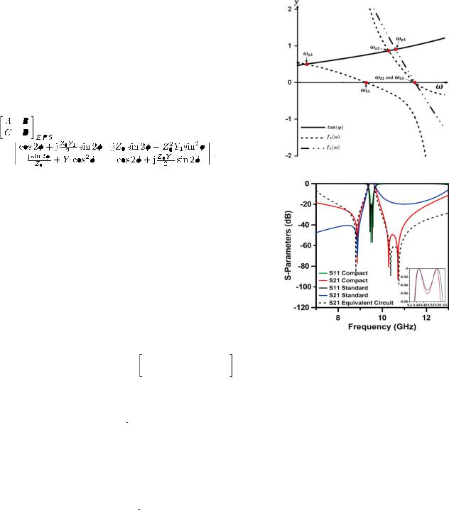
Fig. 2. Solutions to poles and zeros of the ultra compact EPS.
Fig. 3. Comparison of  -parameter responses of the standard
  -plane two-pole EPS, the proposed ultra compact EPS and its equivalent circuit.
|
|
|
|
|
|
|
|
|
|
|
|
|
|
|
|
|
|
|
|
|
|
|
|
|
|
|
|
|
|
|
|
|
|
|
|
|
it is possible to obtain the poles for smaller values of |
|
|
|
that is |
||||||||||
|
|
|
|
|
|
|
|
|
|
|
|
|
|
|
|
|
|
|
|
|
|
|
|
|
|
|
|
|
|
|
|
|
|
|
|
|
|
|
|
||||||||||||
|
|
|
|
|
|
|
|
|
|
|
|
|
(3) |
|
|
||||||||||||||||||||||||||||||||||||
|
|
|
|
|
|
|
|
|
|
|
|
|
equivalent to significant size reduction in comparison |
with the |
|||||||||||||||||||||||||||||||||||||
|
|
|
|
|
|
|
|
|
|
|
|
|
|||||||||||||||||||||||||||||||||||||||
|
|
|
|
|
|
|
|
|
|
|
|
|
|||||||||||||||||||||||||||||||||||||||
|
|
|
|
|
|
|
|
|
|
|
|
|
|
|
|
|
|
|
|
|
|
|
|
|
|
|
|
|
|
|
|
|
|
|
|
|
size of the standard |
|
-plane resonator at the same frequency or |
||||||||||||
|
|
|
|
|
|
|
|
|
|
|
|
|
|
|
|
|
|
|
|
|
|
|
|
|
|
|
|
|
|
|
|
|
|
|
|
|
an EPS with extended length which produces two poles (though |
||||||||||||||
|
|
|
|
|
|
|
|
|
|
|
|
(4) |
it is still comparatively smaller than two standard |
|
-plane res- |
||||||||||||||||||||||||||||||||||||
|
|
|
|
|
|
|
|
|
|
|
|
|
|
||||||||||||||||||||||||||||||||||||||
|
|
|
|
|
|
|
|
|
|
|
|
||||||||||||||||||||||||||||||||||||||||
Two sets of solutions to (3) and (4) can be found as |
|
|
|
|
|
|
|
onator weakly coupled through a long septum) [5]. |
|
||||||||||||||||||||||||||||||||||||||||||
|
|
|
|
|
|
III. ULTRA COMPACT EXTRACTED POLE FILTERS |
|
||||||||||||||||||||||||||||||||||||||||||||
|
|
|
|
|
|
|
|
||||||||||||||||||||||||||||||||||||||||||||
|
|
|
and |
|
|
|
, where |
|
|
|
|
|
|||||||||||||||||||||||||||||||||||||||
|
|
|
|
|
|
|
|
|
|
|
|
|
|
|
|
|
|
|
|
|
|
|
|
|
|
|
|
|
|
|
|
|
|
|
|
|
The EPS in [5] is miniaturized taking advantage of the idea |
||||||||||||||
|
|
|
|
|
|
|
|
|
|
|
|
|
|
|
|
|
|
|
|
|
|
|
|
|
|
|
|
|
|
|
(5) |
expressed in the previous section. For this purpose the two |
|||||||||||||||||||
|
|
|
|
|
|
|
|
|
|
|
|
|
|
|
|
|
|
|
|
|
|
|
|
|
|
|
|
|
|
|
|
|
|
|
|
|
waveguide sections of the phase length |
|
|
|
|
|
, are replaced by |
||||||||
|
|
|
|
|
|
|
|
|
|
|
|
|
(6) |
the corresponding single-mode EPS through the use of extra |
|||||||||||||||||||||||||||||||||||||
|
|
|
|
|
|
|
|
|
|
|
fins in the middle of both waveguide sections of the standard |
||||||||||||||||||||||||||||||||||||||||
|
|
|
|
|
|
|
|
|
|
|
|
|
|
|
|
|
|
|
|
|
|
|
|
|
|
|
|
|
|
|
|
|
|
|
|
|
two pole EPS. Arrangement of the Ultra compact |
|
-plane |
||||||||||||
The locations of the poles determined by (5) and (6) are il- |
insert is presented in Fig. 1(d). |
|
|
|
|
|
|
|
|
|
|
|
|
||||||||||||||||||||||||||||||||||||||
lustrated in Fig. 2, where pole frequencies |
|
|
|
|
|
|
|
|
|
|
|
, |
|
|
|
|
|
|
|
|
|
|
|
|
|
|
|
|
and |
|
|
|
|
|
In order to illustrate the degree of miniaturization achieved |
|||||||||||||||||||||||||||||||||||||||||||||||||||||||||||||
correspond to the |
|
-axis values at the points of intersection of |
by the presented approach, the new ultra compact EPS filter was |
|||||||||||||||||||||||||||||||||||||||||||||||||||||||||||||||||||||||||||||||||||||||||||||
|
||||||||||||||||||||||||||||||||||||||||||||||||||||||||||||||||||||||||||||||||||||||||||||||||
the responses: |
|
|
|
|
|
|
|
|
|
|
|
|
|
|
|
|
|
|
|
|
with that of |
|
|
|
|
|
|
|
|
|
|
|
|
|
|
|
and |
|
|
|
|
|
|
|
|
|
|
|
|
|
|
|
|
|
. Also, |
compared to the standard two pole EPS designed for the same |
||||||||||||||||||||||||||||||||||||||||
transmission zeros at |
|
|
|
|
|
|
- |
|
|
|
|
|
|
are determined by the conditions |
centre frequency of 9.5 GHz and bandwidth of 0.3 GHz with a |
|||||||||||||||||||||||||||||||||||||||||||||||||||||||||||||||||||||||||||||||||
|
|
|
|
|
|
|
|
|
|
|
|
|
|
|
|
|
. The responses in Fig. 2 have been plotted |
transmission zero in lower stopband at the same frequency of |
||||||||||||||||||||||||||||||||||||||||||||||||||||||||||||||||||||||||||||||
|
|
|
|
|
|
|
|
|
|
|
|
|
|
|
|
|
||||||||||||||||||||||||||||||||||||||||||||||||||||||||||||||||||||||||||||||||
using the |
|
relationship between |
|
|
and |
|
|
|
|
|
|
|
|
|
|
|
|
|
|
|
|
|
|
|
|
|
|
|
|
|
|
|
|
|
|
|
|
|
|
|
|
. Here |
|
is |
8.8 GHz. Frequency responses of the structures are compared |
|||||||||||||||||||||||||||||||||||||||||||||||||||
the length of the waveguide section and |
|
|
is the |
|
|
|
|
|
|
|
|
|
|
|
in Fig. 3. |
|||||||||||||||||||||||||||||||||||||||||||||||||||||||||||||||||||||||||||||||||
phase velocity |
||||||||||||||||||||||||||||||||||||||||||||||||||||||||||||||||||||||||||||||||||||||||||||||||
in the waveguide. |
|
|
|
|
|
|
|
|
|
|
|
|
|
|
|
|
|
|
|
|
|
|
|
|
|
|
|
|
|
|
|
|
|
|
|
|
|
|
|
|
|
|
|
|
|
|
|
|
|
|
|
|
|
|
|
|
|
|
|
|
|
|
|
|
|
|
|
|
|
|
|
|
|
|
|
|
|
|
|
As presented in Fig. 2, the proposed structure produces three |
||||||||||||||||
|
It can be noticed from Fig. 2 that the poles |
|
|
|
|
|
|
, |
|
|
|
|
|
|
|
|
|
|
|
|
|
|
and |
|
|
|
|
poles and three transmission zeros. However, the first pole oc- |
||||||||||||||||||||||||||||||||||||||||||||||||||||||||||||||||||||
drift with respect to each other depending on parameters of the |
curs below the waveguide cut-off frequency and can be ne- |
|||||||||||||||||||||||||||||||||||||||||||||||||||||||||||||||||||||||||||||||||||||||||||||||
lines defined by (5) and (6). From (6), for higher values of |
|
|
|
glected. Since the fins are placed closely to one another, the |
||||||||||||||||||||||||||||||||||||||||||||||||||||||||||||||||||||||||||||||||||||||||||||
|
||||||||||||||||||||||||||||||||||||||||||||||||||||||||||||||||||||||||||||||||||||||||||||||||
|
|
|
||||||||||||||||||||||||||||||||||||||||||||||||||||||||||||||||||||||||||||||||||||||||||||||
|
|
|
|
|
|
|
|
|
|
|
|
|
|
|
|
|
|
|
|
|
|
|
|
|
|
|
|
|
|
|
|
|
|
|
|
|
|
|
|
|
|
|
|
|
|
|
|
|
|
|
|
|
|
|
|
|
|
|
|
|
|
|
|
|
|
|
|
|
|
|
|
|
|
|
|
|
|
|
|
|
|
|
|
|
|
|
|
|
|
|
|
|
|
|
|
|

MOHOTTIGE et al.: ULTRA COMPACT INLINE |
|
-PLANE WAVEGUIDE EXTRACTED POLE BANDPASS FILTERS |
411 |
|
|||
|
TABLE I
DIMENSIONS (IN MM) OF THE INSERT FOR FILTER (SEE FIG. 3)
Fig. 4. Simulated and measured  -parameters of the proposed filter.
Fig. 5. Photograph of fabricated filter.
capacitive coupling between them (presented in Fig. 1(c) by capacitance 

 and
and 
 ) and mutual inductances


 result in the splitting of the upper stop band transmission zeros (

 and
and 

 ). The equivalent circuit has been simulated using Agilent ADS software tool. The response of the equivalent circuit is also presented in Fig. 3 by taking into account these additional couplings. It is also visible from the plot that the upper stop-band performance has improved for the new structure at the cost of lower stop-band performance. This decrease is due to the shift in

 towards higher frequencies after the introduction of the new fins.
The length of the fin required for realising the transmission zeros can be found as 


 and the width of the input/output septa as well as the fins were obtained during optimization process to satisfy filter requirements. Final dimensions of the two
  -plane inserts are summarized in Table I. It is clear that the proposed structure is 65% smaller in comparison with
the standard  -plane two pole EPS [5]. Higher order filters based on the proposed structure can be realised through having cascaded sections, or by having extra adjacent fins spaced by transmission line sections between the two septa. In which case a fourth order filter based on the proposed structure is 35 mm, which is 48.5% compact than filters using resonant posts presented in [6].
IV. EXPERIMENTAL VERIFICATION
An ultra compact EPS filter (with centre frequency: 9.45 GHz; passband: 9.35–9.65 GHz; return loss: 20 dB; transmission zeros: 8.8 and 10.2 GHz) has been designed in CST Microwave Studio and fabricated using the  -plane technology which utilizes a single copper insert within the conventional rectangular waveguide. The insert (Fig. 3) with the dimensions given in Table I has been plotted on a copper foil with the thickness 0.1 mm. Then it has been placed within the standard waveguide housing WG-16 (22.86
  10.16
10.16 

 ).
).
 -parameters have been measured using the Agilent E8361A vector network analyzer. The simulated
  -parameter response of the EPS is shown in Fig. 4 together with the experimental data. Insertion loss of the filter was around 1.4 dB. The measured results show good agreement with the simulated. A slight shift in the transmission zeros can also be observed. This is mainly due to the tolerances encountered during fabrication process and the limitation to which the plotter reach. Results can be further improved through meticulous use of the available tools. A photo of the fabricated filter is shown in Fig. 5.
V. CONCLUSION
An ultra compact EPS filter has been proposed in this letter. The proposed filter is 65% smaller in comparison with the standard two pole EPS and produces three transmission zeros which can be realized both at the upper and the lower stop-bands. The new structure has been designed, fabricated and tested. Considering the inaccuracies involved in practical realization of the proposed filter, the agreement between simulation and measurement is very good. In addition, a higher order filter based on these structures retains the merit of compact size.
REFERENCES
[1]Y. Konishi and K. Uenakada, “The design of a bandpass filter with inductive strip planar circuit mounted in waveguide,” IEEE Trans. Microw. Theory Tech., vol. MTT-22, pp. 869–873, Oct. 1974.
[2]A. Shelkovnikov and D. Budimir, “Left-handed rectangular waveguide bandstop filters,” Microw. Opt. Technol. Lett., vol. 48, no. 5, pp. 846–848, 2006.
[3]N. Suntheralingham and D. Budimir, “Enhanced waveguide bandpass filters using S-shaped resonators,” Int. J. RF Microw. CAE, vol. 19, no. 6, pp. 627–633, 2009.
[4]O. Glubokov and D. Budimir, “Extraction of generalized coupling coefficients for inline extracted pole filters with nonresonating nodes,”
IEEE Trans. Microw. Theory Tech., vol. 59, no. 12, pp. 3023–3029, Dec. 2011.
[5]O. Glubokov and D. Budimir, “Novel inline waveguide  -plane filters using dual-mode extracted pole section,” in Proc. 41st Eur. Microw. Conf. (EuMC), Oct. 10–13, 2011, pp. 99–102.
[6]C. Tomassoni and R. Sorrentino, “A new class of pseudo-elliptic waveguide filters using resonant posts,” in IEEE MTT-S Int. Dig., Jun. 17–22, 2012, p. 1,3.