

диафрагмированные волноводные фильтры / abe6722a-8f32-4538-ac75-52b354284a68
.pdfA Novel E-Plane Substrate Inserted Bandpass Filter with High Selectivity and Compact Size
J. Y. Jin,1 X. Q. Lin,1 Y. Jiang,1 L. Wang,2 Y. Fan1
1EHF Key Lab of Fundamental Science, School of Electronic Engineering, University of Electronic Science and Technology of China, Chengdu 611731, China
2Department of Electrical and Computer Engineering, Dalhousie University, Halifax B3J 2X4, Canada
Received 13 May 2013; accepted 22 August 2013
ABSTRACT: In this article, a novel E-plane substrate inserted waveguide bandpass filter with high selectivity and compact size is proposed in Ka-band. By integrating an extra resonator between two metal septa, the E-plane waveguide filter is achieved with two transmission zeros at both sides of the passband which contribute to the high-skirt selectivity. One sample is fabricated, whose total length is just 5 mm, namely, less than 0.5 kg and the minimum insertion loss is only about 0.3 dB. Good agreements between simulated and measured results are obtained.
Keywords: E-plane filter; high selectivity; compact size; waveguide filter
I. INTRODUCTION
In some microwave and millimeter-wave systems, the waveguide filters are preferred because of their high cavity quality (Q) value, low insertion loss, large rejection, and high power capacity. There are different kinds of methods to accomplish waveguide filter. First, the simple implementation of waveguide filter technology is composed of waveguide cavities coupled through thick inductive irises [1–3]. Generally, to overcome the drawback of low-cost manufacturing techniques, this waveguide topology always consists on the use of tuning screws. Second, the dual-mode or multimode waveguide filters can implement nonadjacent couplings between resonators, resulting in more complex filtering functions [4, 5]. Although this kind of waveguide filter can provide improved selectivity and insertion loss performance, high cost and hard integration are inevitable. Finally, E-plane metal inserted waveguide filter is another classical implementation of waveguide filters. Since the waveguide E-plane septum filter was introduced by Konishi and Uenakada [6], it has become an important filter structure [7, 8]. In this filter configuration, the impedance inverter constants of the half-wave prototype are synthesized through the thin metal septa inserted in the midplane of waveguide. An important advantage of this kind of wave-
guide filter is related to its easy manufacturing process, which is very suitable for low cost and mass production. To improve the performance, some improved filters are reported. The novel E-plane waveguide filters with periodically loaded resonators were introduced in [9]. The broadband E-plane filters were presented in Ref. [10]. Some other novel E-plane waveguide filters were researched in Refs. [11–13]. However, good performance of those waveguide filters is achieved almost by cascading more than one cell, which leads to large structure size and high insertion loss. Some researchers have also investigated to improve the performance of E-plane waveguide filter using the crosscouplings between nonadjacent resonators or based upon the concept of nonresonating nodes [14–16].
In this article, we propose a novel compact E-plane insert waveguide filter by adding an extra resonant cell between the two metal septa to fabricate the new circuit structure resulting in the electrical and magnetically resonances. Two transmission zeros are caused by the resonances, which contribute to achieve the sharp attenuation beside the both sides of the passband. One proposed E-plane filter is fabricated and tested, where good agreement is obtained between simulated and measured results.
II. DESIGN AND ANALYSIS
Correspondence to: X. Q. Lin; e-mail: xqlin@uestc.edu.cn. DOI: 10.1002/mmce.20785
Published online 4 November 2013 in Wiley Online Library (wileyonlinelibrary.com).
A. Characteristics of E-Plane Waveguide Filters with Only Two Metal Septa Inserted
Before the analysis of our proposed filter, we first pay attention to the characteristics of E-plane waveguide
VC 2013 Wiley Periodicals, Inc.
451

452 |
Jin et al |
Figure 1 E-plane waveguide filters with two metal septa (w 5 0.3 mm).
filters with only two metal septa resulting in a half-wavelength resonator. The half-wavelength resonator is fabricated on the Rogers 5880 substrate (with thickness of 0.254 mm and relative permittivity er 5 2.2), which is inserted in E-plane of a standard Ka-band waveguide (WR 28 with a 5 7.112 mm and b 5 3.556 mm), as shown in Figure 1. The simulation results are calculated using Ansoft HFSSTM which is a commercial finite- element-based electromagnetic mode solver. When fixed the width of the metal septa, its bandpass properties are controlled by the distance between two metal septa d. In rectangular waveguide, the guide wavelength is
k
kg5 p (1) 12ðk=kcÞ
Figure 2 The layout of the proposed bandpass filter: (a) perspective view and (b) circuit structure on substrate.
Figure 3 A simulation result (d 5 4.4 mm, w 5 0.3 mm, w2 5 0.2 mm, g 5 0.1 mm, l1 5 3 mm, l2 5 2.8 mm, and l3 5 1 mm).
where kg is the waveguide wavelength, k is the free space wavelength, and kc is the cutoff wavelength. When d 5 4 mm and 4.4 mm, the center frequencies of passband are 30.7 GHz (kg 5 13.45 mm) and 31.8 GHz (kg 5 12.38 mm), respectively. Affected by a negative length brought by the K-impedance inverters, the distance between the two metal septa is slightly less than 0.5 kg [17, 18]. And the normalized K-impedance inverter value and negative electrical length can be approximately given by [18].
From Figure 1, the E-plane filter with only one halfwavelength resonator structured by two metal septa has slow attenuation in the stopband. In Ref. [17], good performance was achieved by cascading five half-wavelength resonators. But in this article, we would like to take some other novel techniques to improve the attenuation performance before its practical application.
B. Design of the Proposed Filter
In our study, we would like to add an extra resonator in the half-wavelength resonator instead of cascading several resonators. The basic purpose is to bring transmission zeros into the stopband of original E-plane waveguide filter. Thus, new passband will be created with different performances. Figure 2 shows the layout of the proposed E- plane waveguide filter.
According to the proposed bandpass filter structure, a simulation result is show in Figure 3. We can find that the novel E-plane substrate inserted waveguide bandpass filter structure has two transmission zeros at both sides of the passband which contribute to the high-skirt selectivity. The two transmission zeros are caused by the electric and magnetic resonances.
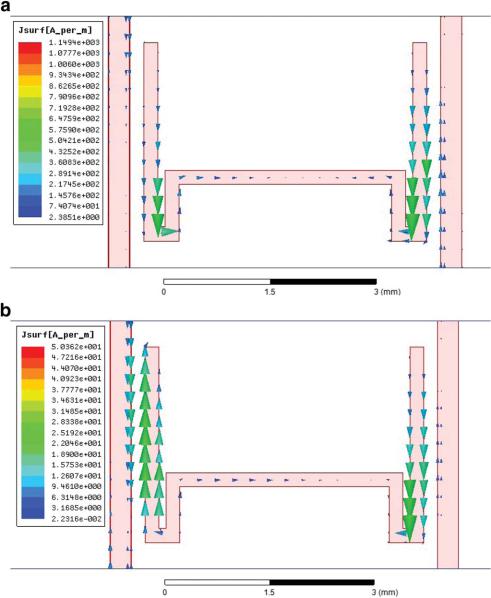
The electric resonance is caused by the extra resonator. The lower transmission zero is introduced by this resonance. The surface current distribution on the metal structures of the E-plane filter at the lower transmission zero frequency is illustrated in Figure 4a, where we observe that the symmetric current distribution is obtained, which results in an effective PEC at the central face.
International Journal of RF and Microwave Computer-Aided Engineering/Vol. 24, No. 4, July 2014
Novel E-Plane Substrate Inserted Bandpass Filter |
453 |
Figure 4 The surface current distributions: (a) at the lower transmission zero frequency (29.19 GHz) and (b) at the upper transmission zero frequency (34.97 GHz).
The magnetic resonance is mainly caused by the extra resonant cell and the adjacent metal strip. The upper transmission zero is introduced by this resonance. The surface current distribution on the metal structures of the E-plane filter at the upper transmission zero frequency is illustrated in Figure 4b, where we observe that approximate continue current distribution is obtained.
C. Parameter Analysis for the Proposed Filter
In this subsection, we want to analyze the main parameters of the proposed filter. When we fixed the two metal septa with d 5 4.4 mm and w 5 0.3 mm, there are other four parameters of the extra resonator to characterize the proposed filter, that is, l1, l2, l3, g, w2. In our design, we
fixed w2 5 0.2 mm and g 5 0.1 mm. We focus on the impact of the three length parameters l1, l2, and l3.
From Figure5a, we can see that a smaller l1 with fixed l2 5 2.8 mm and l3 5 0.5 mm results in a narrower bandwidth. The lower transmission zero point is impacted more than the upper transmission zero point by changing the length of l1.
From Figure 5b, the length of l2 with fixed l1 5 3 mm and l3 50.5 mm increases along with the frequency declining and this parameter mainly changes the upper transmission zero frequency point.
From Figure 5c, when fixed l1 5 3 mm and l2 5 2.8 mm, we know that the lower transmission zero, the upper transmission zero, and the central frequency of passband
International Journal of RF and Microwave Computer-Aided Engineering DOI 10.1002/mmce

Figure 5 The simulation results for: (a) l1 with fixed l2 5 2.8 mm and l3 5 0.5 mm, (b) l2 with fixed l1 5 3 mm and l3 5 0.5 mm, and (c) l3 with fixed l1 5 3 mm and l2 5 2.8 mm.
Figure 6 The novel E-plane filters (d 5 4.4 mm, w 5 0.3 mm, w2 5 0.2 mm, g 5 0.1 mm, l2 5 2.8 mm, l1 5 3 mm, and l3 5 0.5 mm).

Figure 7 Simulated and measured results.
are simultaneously moved down if the length of l3 is increased.
The parameters l1, l2, and l3 change the effective electric length of electric and magnetic resonances. Here, we must notice that the effective electric length of electric resonance should be longer than that of magnetic resonance because the lower transmission zero must be caused by the electric resonance. So designing such a filter, we must consider and estimate the extra resonant cell.
In summary, in design of our proposed filter, no additional size is required because our extra resonator is between of these two metal septa. The extra resonator with both electronic and magnetic resonances will create corresponding transmission zeros beside both sides of the passband to improve the selectivity. Moreover, another advantage is that by changing the size of resonator properly, we can easily adjust the operating frequency band of our proposed filter.
Finally, we would like to figure out that there is a parasitic passband locating above our designed frequency band. Actually, this passband is mainly affected by cavity resonance, which can be further weakened by adding other bandstop structure [19] on the opposite face of the inserted substrate when needed in practical application.
III. EXPERIMENT
In this section, a sample of novel E-plane substrate inserted bandpass filter is fabricated to testify the above analysis. Photograph of the filter is presented in Figure 6. In our experiment, we make use of the standard waveguide WR 28 in our laboratory with a waveguide length of 20 mm, so the sample is fabricated longer. The simulated and measured results are shown in Figure 7. Two transmission zeros occur at both sides of the passband, which significantly contribute to the sharp attenuation in the stopband. The filter has been tested using the Agilent Technologies A8757D network analyzer. It can be concluded from comparison of simulated and experimental results that agreement is quite good taking into account
Novel E-Plane Substrate Inserted Bandpass Filter |
455 |
|||
inaccuracies |
of |
manufacturing, |
assembling, |
and |
measurement. |
|
|
|
|
IV. CONCLUSION
In this article, we propose a kind of novel E-plane substrate inserted bandpass filter with high selectivity and compact size whose total length is less than 0.5 kg. By adjusting the size of the extra resonator rather than changing the length of the filter, we can receive different operating frequency bands. One sample of the proposed E- plane bandpass filter is fabricated and measured. High selectivity is obtained with two transmission zeros locating at both sides of the passband. This kind of waveguide filter not only shows low insertion losses compared with conventional counterparts but also has size reduction and considerable improvements in frequency selectivity.
ACKNOWLEDGMENTS
This work was supported, in part, by the National Science Foundation of China under Grant No. 60901022, the Research Fund for the Doctoral Program of Higher Education under Grant No.20090185120005, by the Fundamental Research Funds for the Central Universities under Grant No. ZYGX2010J021, and by MTT-Society.
REFERENCES
1.R. Levy, R.V. Snyder, and G. Matthaei, Design of microwave filters, IEEE Trans Microwave Theory Tech 50 (2002), 783– 793.
2.R. Levy, Theory of direct-coupled-cavity filters, IEEE Trans Microwave Theory Tech 15 (1967), 340–348.
3.Y. Zhai, Q. Wang, Z. Wang, and X.X. Gao, The design of an Iris waveguide filter at 35.75 GHz, in GSMM 2008 Global Symposium on Millimeter Waves, 2008, pp. 348–350.
4.A.E. Williams, A four-cavity elliptic waveguide filter, IEEE Trans Microwave Theory Tech 18 (1970), 1109–1114.
5.A.E. Atia and A.E. Williams, Narrow-bandpass waveguide filters, IEEE Trans Microwave Theory Tech 20 (1972), 258– 265.
6.Y. Konishi and K. Uenakada, The design of a bandpass filter with inductive strip—Planar circuit mounted in waveguide, IEEE Trans Microwave Theory Tech 22 (1974), 869–873.
7.R. Vahldieck, J. Bornemann, F. Arndt, and D. Grauerholz, Optimized waveguide E-plane metal insert filters for millimeter-wave applications, IEEE Trans Microwave Theory Tech 31 (1983), 65–69.
8.S. Yi-Chi and T. Itoh, E-plane filters with finite-thickness septa, IEEE Trans Microwave Theory Tech 31 (1983), 1009– 1013.
9.G. Goussetis and D. Budimir, Novel periodically loaded E- plane filters, Microwave Wireless Compon Lett 13 (2003), 193–195.
10.Z. Xu, J. Guo, C. Qian, and W. Dou, Broad-band E-plane filters with improved stop-band performance, IEEE Microwave Wireless Compon Lett 21 (2011), 350–352.
11.D. Budimir, O. Glubokov, and M. Potrebic´, Waveguide filters using T-shaped resonators, Electron Lett 47 (2011), 38.
12.A. Shelkovnikov and D. Budimir, Miniaturized rectangular waveguide filters, Int J RF Microwave Comput Aided Eng 17 (2007), 398–403.
International Journal of RF and Microwave Computer-Aided Engineering DOI 10.1002/mmce

456 |
Jin et al |
13.N. Suntheralingam and D. Budimir, Enhanced waveguide bandpass filters using S-shaped resonators, Int J RF Microwave Comput Aided Eng 19 (2009), 627–633.
14.O. Glubokov and D. Budimir, Compact E-plane doublet structures for modular filter design, 2010 European in Microwave Conference (EuMC), 2010, pp. 1253–1256.
15.O. Glubokov and D. Budimir, Extraction of generalized coupling coefficients for inline extracted pole filters with nonresonating nodes, IEEE Trans Microwave Theory Tech 59 (2011), 3023–3029.
16.O. Glubokov and D. Budimir, Compact filters using metaldielectric inserts, 2012 42nd European in Microwave Conference (EuMC), 2012, pp. 1103–1106.
17.Z. Wang, R. Xu, Y. Guo, Y. Zhang, and B. Yan, A highly integrated KA-band transceiver module with two channels, Microwave Opt Technol Lett 52 (2010), 615–618.
18.G.L. Matthaei, L. Young, and E. Jones, Microwave filters, impedance-matching networks, and coupling structures, vol. 1964, Artech House, Dedham, MA, 1980.
19.Y. Zhang, W. Hong, Z.-Q. Kuai, and J.-Y. Zhou, A compact multiple bands notched UWB antenna by loading SIR and SRR on the feed line, in International Conference on Microwave and Millimeter Wave Technology, 2008, pp. 198–201.
BIOGRAPHIES
Jun Ye Jin was born in Inner Mongolia, China, in 1988. She received the B.S. degree in electromagnetics and microwave technology in 2011 and is now studying for a master’s degree in the School of Electronic Engineering from the University of Electronic Science and Technology of China. Her research interests include microwave or millimeter-wave circuits and sys-
tems and antenna. Ms. Jin was a recipient of the Spring 2012 IEEE MTT-S Undergraduate=Pre-Graduate Scholarship.
Xian Qi Lin was born in Zhejiang Province, China, on July 9, 1980. He received the B.S. degree in electronic engineering from UESTC (University of Electronic Science and Technology of China), Chengdu, China, in 2003, and Ph.D. degree in electromagnetic and microwave technology from Southeast University, Nanjing, China, in 2008. He joined the Department of Micro-
wave Engineering at UESTC in August 2008, and became an associate professor in July 2009. From September 2011 to September 2012, he was a postdoc researcher in the Department of Electromagnetic Engineering at Royal Institute of Technology (KTH), Stockholm, Sweden. His research interests include microwave=millimeter-wave circuits, metamaterials, and antennas.
Yuan Jiang was born in Jiangsu, China. He received the B.S. degree in 2010 and is now taking a successive postgraduate and doctoral program in electronic engineering from the University of Electronic Science and Technology of China. His research interests include microwave circuits and systems.
Luyu Wang was born in Sichuan Province, China. He received the B.Eng. degree in electromagnetic field and radio technology from University of Electronic Science and Technology of China, Chengdu, China, in 2011, and is now working toward the MASc degree in Electrical Engineering at Dalhousie University, Halifax, Canada. His research interests include plasmonics, non-
linear optics, statistical singular optics, microwave resonators=filters, and metamaterial transmission lines. Mr. Wang was a recipient of the Spring 2011 IEEE MTT-S Undergraduate=Pre-Graduate Scholarship.
Yong Fan was born in 1963. He received the B.E. degree from Nanjing University of Science and Technology, Nanjing, Jiangsu, China, in 1985, and the M.S. degree from University of Electronic Science and Technology of China, Chengdu, Sichuan, China, in 1992. From 1985 to 1989, he was interested in microwave integrated circuits. Since 1989, he dedicated himself to
researching and teaching on subjects of electromagnetic fields and microwave techniques for many years. His main research fields are as follows: electromagnetic theory, millimeter-wave communication, and millimeter-wave and Terahertz Circuits. Besides, he was interested in other subjects including broadband wireless access, automobile anticollision, and intelligent transportation.
International Journal of RF and Microwave Computer-Aided Engineering/Vol. 24, No. 4, July 2014