

диафрагмированные волноводные фильтры / a2f3ba7b-7d80-4a31-83c6-dd1de8ae6038
.pdfInternational Journal of Electrical and Computer Engineering (IJECE) |
|
Vol. 10, No. 6, December 2020, pp. 5861~5870 |
|
ISSN: 2088-8708, DOI: 10.11591/ijece.v10i6.pp5861-5870 |
5861 |
Radiation performance enhancement of an ultra wide band antenna using metamaterial band-pass filter
Marwa Daghari1, Hedi Sakli2
1,2MACS Research Laboratory, National Engineering School of Gabes, Gabes University, Tunisia 2EITA Consulting 5 Rue du Chant des oiseaux, France
Article Info
Article history:
Received Mar 11, 2020
Revised May 5, 2020
Accepted May 18, 2020
Keywords:
Band-pass filtering response Frequency selective surface Metamaterials
Transverse electric
Ultra wide band applications
ABSTRACT
In this paper, a metamaterial structure based on frequency selective surface (FSS) cell is proposed to achieve an isotropic band-pass filtering response. This filter consists of a planar layer formed by a 3×3 metamaterials cell array with transmittive filtering behavior at 3.5 GHz. This design with 45×45 mm dimension is then integrated in close proximity at distance of 10 mm with an ultra wide band (UWB) antenna to enhance it’ s performances around a 3.5 GHz operating frequency. Simulation results ensure that filter geometry provides the advantage of the angular stability up to to 45◦ and also polarization modes independency (transverse electric (TE) and transverse magnetic (TM)). In addition, enhancement in antenna radiation pattern characteristics is enhanced especially when the FSS filter layer is integrated at a very close distance from the radiator. Moreover, antenna gain was improved to 3.22 dBi, adaptation of antenna port (S11) was increased to -53.26 dB and antenna bandwidth reduction to 1.7 GHz is also detected. All these performances make the proposed design as a good choice used to shield signals in UWB wireless applications especially for connected object in 5G.
Copyright © 2020 Institute of Advanced Engineering and Science. All rights reserved.
Corresponding Author:
Marwa Daghari,
MACS Research Laboratory,
National Engineering School of Gabes,
Gabes University, 6029, Tunisia.
Email: marwadaghari@gmail.com
1.INTRODUCTION
During the past decade, ultra-wide band (UWB) technology has attracted attention in many applications that require high data rate and maximum bandwidth utilisation [1]. Printed antennas, particularly monopoles are commonly used as radiators in ultra-wide band electronic devices due to their compact size, low profile, low fabrication cost, omnidirectional and bidirectional radiation pattern and ultra-wide impedance bandwidth. However, particularly at lower frequencies, this type of antenna usually suffers from reduced main lobe gain, poor directivity, large back radiation and its susceptibility to the surrounding environment which makes them inefficient [2]. Nevertheless, there are many technical solutions applied in the antenna construction to overcome those defects. One of them is metamaterials [3]. These last are a composite media made up of an arrangement of metal structures on the surface of dielectric substrates. They can be engineered to have unique electromagnetic properties and integrated after in antenna design to exhibit many application requirements [4-6]. In other researches, metamaterials structures are applied in RFID (radio frequency identification) tags in order to augment the read range and to decouple the tag with the tagged object [7]. But the major involvement of metamaterials is in antenna structure to improve its functional parameters. Authors in [8, 9] suggest a composite right left-handed (CRLH) metamaterial to beam scanning of a leaky wave antenna. Also, for UWB antenna many metamaterial configurations are proposed to
Journal homepage: http://ijece.iaescore.com/index.php/IJECE

5862 |
ISSN: 2088-8708 |
||
|
|
|
|
ensure multi band behavior [10, 11], to enhance bandwidth [12, 13] and to preserve compactness aspect of the hole structure [14, 15].
Frequency selective surfaces (FSS) are a popular metamaterials structures that provide filtering proprieties. FSS when they are properly designed, can probably ameliorate the radiation characteristics of printed UWB antennas and also shield the electronics beneath them. Generally, FSSs are constructed by the repetition of a pre-designed unit cell to give them the periodic antennas as well as shield the electronics beneath them structures specificity. Depending on their unit cell geometry, FSSs act as spatial filters [16]. They can be designed to alow electromagnetic (EM) waves to move across them in the case of band pass FSS or return back them if it is band stop FSS [17]. Their performing filtering behavior is generally a function of the structure, the operating frequency and the incoming EM wave polarization. Based on the above principle the FSS can combined with the UWB antenna to enhance its performance [18, 19].
In recent literature, some single-layer FSS reflectors are designed to achieve constant gain in the UWB band [20-22]. In [23], FSS is used to reduce Radar Cross Section (RCS) of microstrip array antenna. In fact, the proposed FSS cell is with reflective property over the low band 1.9-7.5 GHz and also with transmitive performance at 11.05 GHz. It is simultaneously applied to reduce the out-of-band RCS and preserve the antenna array radiation performance. In [24, 25], conical FSS radome integrated in a small distance of a monopole antenna is presented. This stucture shows a narrow pass-band response which is very useful for out of band RCS control. In [26], Ayan Chatterjee proposed a monopole dielectric resonator antenna with a cylindrical FSS for radiation diversity application. The FSS is reflective at 5 GHz and when it is placed close to the monopole improve the antenna bandwidth from 26.8 % to 53.67 % in 4-6 GHz. In addition, in [27], the basic metamaterial circular and square rings are used to achieve a stopband response characteristic. In the study presented in [28], two compact UWB frequency selective surface reflectors are proposed for antenna gain enhancement applications. The FSS, which is a 10×10 array with 8.25×8.25 mm unit size, not only enhances the gain of the UWB antenna, but also guarantees a constant gain with only 0.5 dBi variation across the whole operation band. Furthermore, an 8×8 array of I-shaped FSS structures was introduced in [29] and led to an increase in gain of the monopole slot antenna radiation pattern to be used for several wireless and X-band applications. In [30], a 6×6 array of the FSS cell was integrated with a dual-slot antenna to be useful for a circular polarization application over the 4.5–8.0 GHz band in vehicular radar and ground penetrating radar.
We propose in this work a planar compact filter-antenna module for wireless UWB applications. This filter is transmittive at 3.5 GHz frequency. It is fabricated with an array of FSS cells and integrated then with a UWB elliptical antenna at a close distance of λ0/8 in order to improve its radiation characteristics in directivity, gain, and bandwidth. Simulations results shows a good isotropic filtering response of the proposed structure with the variation of incident wave angle and polarization. Also, antenna gain, directivity and adaptation (S11) are improved which is very suitable for UWB wireless applications around 3.5 GHz.
The rest of the paper is organised as follows: The proposed FSS unit cell design and simulations is described in Section 2. Then, in section 3, integrated module antenna-filter design and simulations characteristics are detailed and also discussed. Finely conclusions are summarized in the last section.
2.FSS UNIT ELEMENT DESIGN AND SIMULATIONS
Different FSS elements have been studied for band-pass response [22]. The FSS unit cell presented here is designed for the purpose of a single transmission at 3.5 GHz. The unit cell element geometry is a D×D rectangular metallic patch with a thickness of t and a square loop slot with a width of a located at a distance of S from the extremity of the cell. This patch is glued to the paper low-cost FR-4 substrate with relative permittivity of 4.3, dielectric loss tangent of 0.025 and thickness of 1.6 mm. This design is illustrated in Figure 1 as Figure 1(a) shows the front side view and Figure 1(b) shows the 3-D perspective view of the proposed FSS cell. In order to find out the best geometrical dimension parameters values at 3.5 GHz operating frequency, the unit cell is designed and simulated. The frequency range for this optimization is taken from 1 to 5 GHz. Optimized values for different parameters are shown in Table 1.
Table 1. Optimized geometry parameters values of the proposed FSS unit cell
Parameters |
Values (mm) |
Periodicity: D |
15 mm |
Square loop slot width: a |
1.1 mm |
Big square loop width: S |
0.7 mm |
Int J Elec & Comp Eng, Vol. 10, No. 6, December 2020 : 5861 - 5870

Int J Elec & Comp Eng |
ISSN: 2088-8708 |
5863 |
(a) |
(b) |
|
Figure 1. (a) Front side view, (b) 3-D perspective view
Now, to study the characteristics of the proposed FSS, simulation setups are made to calculate Sparameter (S11, S21) values in TE/TM modes and also for normal and oblique incidences of the wave. In Figure 2 the simulated transmission coefficient for TE and TM modes are ploted. Results prove that the FSS cell has a band-pass band filter behavior with a 1.65 GHz bandwidth at 3.5 GHz center frequency. S-parameter values (S11, S21) in TE and TM modes are identical. It is seen that the cell filtering comportment is the same for both a horizontally (TE mode) and vertically (TM mode) polarized E-field. So, the FSS cell has an isotropic response to the polarization mode. The simulated S-parameter coefficient (S21) of this proposed FSS at different incidence angles and also different polarizations are shown in Figure 3. It is noticed that the FSS response with the variation of incident angle wave is opposite for TE mode in Figure 3(a) and TM mode Figure 3(b). The TE mode is more sensitive to the variation of angle of incidence in comparison with the TM mode. This is due to the fact that the surface impedance is proportional to the angle of incidence in the TM mode whereas in TE mode, it is the opposite. But it may be observed that, the transmission zero (S21) does not significantly change and remains lower than -0.6 dB up to an angle of 45◦ for the two polarization modes. So, independently of modes, FSS cell wave reflection performance at 3.5 GHz is verified and it can be said that FSS has a independent performance for different polarizations and incidence angles.
Figure 2. FSS s-parameters simulation for TE mode
Radiation performance enhancement of an ultra wide band antenna using metamaterial ... (Marwa Daghari)

5864 |
ISSN: 2088-8708 |
||
|
|
|
|
(a) (b)
Figure 3. FSS unit cell reflection characteristics at different angles of incidence,
(a)TE mode, (b) TM mode
3.INTEGRATED DESIGN OF ANTENNA AND FSS FILTER
3.1.2D planar FSS array design and simulations
As a definition, FSS is a periodic arrangement of 1-D or 2-D resonant structures. The FSS cell studied above is used to construct a planar layer of 3×3 array elements. The topology of the proposed 2-D single layer planar is illustrated in Figure 4.
The behavior of this FSS is verified under normal and oblique incidence for TE and TM modes. The simulated transmission characteristics are shown in Figure 5. As we can see, the results verify that planar FSS structure gives identical filtering response in both TE and TM modes. We can draw the conclusion that
the FSS layer has an excellent polarization stability. Now, to validate the band-pass characteristics of the proposed 2-D layer, performances under oblique incidence are also presented in Figure 6. As can be seen show in these figures, when the incident angle increases to 45°, the S21 value in TE mode and TM mode at 3.5 GHz resonant frequency is still below to -1 dB. Subsequently, the proposed structure has an efficient resonance stability for oblique incident angles at different polarizations. So, results are in good agreement with the band-pass filter behavior of the unit cell.
Figure 4. Topology of 2-D planar FSS of 3 × 3 unit cells
Figure 5. Transmission and reflexion coefficient variations of 2-D planar FSS
Int J Elec & Comp Eng, Vol. 10, No. 6, December 2020 : 5861 - 5870

Int J Elec & Comp Eng |
ISSN: 2088-8708 |
5865 |
(a) |
(b) |
Figure 6. Reflection coefficient versus frequency for different incident angle, (a) TE mode, (b) TM mode
3.2. Antenna element design and simulations
A printed elliptical patch antenna is proposed in this paper as a reference antenna which exhibits good performances through the UWB frequency range (3.1 GHz - 10.6 GHz). The basic geometry of the antenna is shown in Figure 7. In fact, Ws×Ls FR-4 substrate of thickness h=1.6 mm, relative permittivity εr=4.4 and loss tangent tgδ=0.02 is used. Ground plane is chosen to be rectangular with dimensions Wg×Lg. The two axes of antenna are represented by 2a and 2b parameters. The parameter p is the gap distance separating the radiating element and the ground plane. The antenna is excited via 50Ω microstrip lines of
Wf=3 mm of width. These design parameters were calculated and optimized to obtain a well-comportment in UWB and especially at 3.5 GHz operating frequency [31]. They are listed in Table 2.
Table 2. Optimized parameters of elliptical antenna (mm)
Patch layer |
Ground Layer |
Substrate Layer |
a: 14.5 mm |
Lg=19 mm |
Ls= 45 mm |
b: 10 mm |
Wg= 45 mm |
Ws=45 mm |
p: 0.4 mm |
|
|
Figure 7. Geometry of elliptical UWB antenna
Radiation performance enhancement of an ultra wide band antenna using metamaterial ... (Marwa Daghari)

5866 |
ISSN: 2088-8708 |
||
|
|
|
|
Antenna reflection coefficient (S11) simulations results curves against using the optimized parameter values involved in Table 2 are presented in Figure 8. It can be observed that S11 values are already lower then -10 dB level through the UWB frequency band (3.1-10.6 GHz). Therefore, the proposed antenna demonstrates acceptable performances in UWB.
Antenna simulated radiation patterns on 2-D view at 3.5 GHz frequency in the H-plane (x-z plane), and E-plane (y-z plane) are shown respectively, in Figure 9. We can notice that the elliptical antenna has omnidirectional radiation patterns which is typical to UWB monopole antenna radiation. All antenna parameters in gain, directivity, S11 and radiation efficiency are reported and summarized in Table 3. We can conclude that the proposed elliptical antenna radiates with good performance at 3.5 GHz operating frequency.
Figure 8. Return loss variation of elliptical antenna.
Figure 9. 2-D view of radiation pattern of elliptical antenna at 3.5 GHz
Table 3. Elliptical antenna performance at 3.5 GHz
Parameters |
Values |
S11 |
-17.91 dB |
Gain |
2.75 dBi |
Directivity |
3.1 dBi |
Efficiency |
-0.4 dB (95%) |
Bandwidth |
7.5 GHz |
Int J Elec & Comp Eng, Vol. 10, No. 6, December 2020 : 5861 - 5870

Int J Elec & Comp Eng |
ISSN: 2088-8708 |
5867 |
3.3. UWB antenna with FSS design and simulations
To verify the effect of the proposed structure of FSS filter at 3.5 GHz, the layer of 3×3-unit cells studied in the previous section is placed above the UWB elliptical antenna at a distance of 10 mm which is near to λ0/8 with respect to the 3.5 GHz center frequency. The elliptical antenna is placed on the center axis of the FSS layer to ensure axi-symmetry of the whole structure. Proposed design of the module filter-antenna is showed in Figure 10.
Figure 10. Monopole elliptical antenna with FSS structure
Simulations of the composite design with and without the FSS layer are performed. Simulated reflection coefficient (S11) results are shown in Figure 11. It can be seen that, the input reflection coefficient value changes significantly and it improves from -17.91 dB to -53.26 dB at 3.5 GHz. Furthermore, -10 dB bandwidth of 1.7 GHz of the antenna around the 3.5 GHz operating frequency is detected. So, it is much narrower which is very suitable for decreasing signal interferences in multi-frequency UWB antennas.
Figure 11. Return loss of the antenna with/without FSS structures
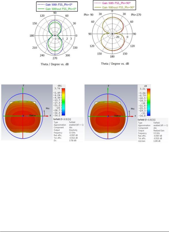
2-D radiation patterns with φ=0◦ and φ=90◦ at 3.5 GHz of the antenna-filter are shown in Figure 12. From this figure it is observed that, the omnidirectional radiation characteristics of the antenna are kept. In addition, it is also clearly observed from Figure 13, that with FSS, antenna gain is equal to 3.22 dBi, directivity is 3.77 dBi and total efficiency of 96% at the operating frequency of 3.5 GHz. From Table 4, it is shown that gain, directivity and efficiency of the antenna with the use of the FSS filter layer are increased. These results can be justified by the presence of constructive interferences of radiated and
Radiation performance enhancement of an ultra wide band antenna using metamaterial ... (Marwa Daghari)
5868 |
ISSN: 2088-8708 |
||
|
|
|
|
reflected waves in the direction opposite to the FSS layer. Usually normal printed monopole antennas suffer from reduced gain which makes them inefficient. In this work, and from the above results, we can conclude that radiation performance of the antenna is well improved. So, conformal FSS layer can operate as a radio frequency filter which can be added directly to the antenna. As a consequence, this filter can used in shielding antenna by reducing interferences and especially in UWB wireless applications (i.e. connected object applications in 5G).
Figure 12. Radiation pattern (gain) on 2-D view for phi=0°and phi=90° of antenna with/without FSS layer
Figure 13. 3-D view of radiation pattern for elliptical antenna with FSS filter, (a) Directivity, (b) Gain
Table 4. Elliptical antenna performance at 3.5 GHz without and with FSS
Parametres |
Antenna without FSS |
Antennaa with FSS |
S11 |
-17.91 dB |
-53.26 dB |
Gain |
2.75 dBi |
3.22 dBi |
Directivity |
3.1 dBi |
3.72 dBi |
Efficiency |
-0.4 dB (95%) |
-0.5 dB (96%) |
Bandwidth |
7.5 GHz |
1.7 GHz |
A comparison of the antenna characteristics (i.e. frequency range, bandwidth, gain, radiation efficiency) and filtering behavior (FSS reflection efficiency, FSS angle of incidence stability) of the proposed antenna-filter structure with few other works recently reported is given in Table 5. It is observed that
the |
proposed |
antenna with FSS |
filter exhibits an |
excellent adaptation, a narrow frequency range |
and |
an |
acceptable |
gain value. Also, |
for the proposed |
design, a good filtering behavior is illustrated |
with |
an insensibility for wave angle of incidence up to 45◦ compared with mentioned researches. |
|
||||
Int J Elec & Comp Eng, Vol. 10, No. 6, December 2020 : 5861 - 5870

Int J Elec & Comp Eng |
ISSN: 2088-8708 |
|
5869 |
||
Table 5. Comparison of the proposed antenna with the previous designs in the cited references |
|||||
|
|
[32] |
[23] |
Proposed |
|
|
Operating frequency |
5.2 GHz |
11 GHz |
3.5 GHz |
|
|
Dimensions |
108×108 mm2 |
51.6×51.6 mm2 |
45×45 mm2 |
|
|
Antenne efficiency |
-0.7 dB |
-0.5 dB |
-0.5 dB |
|
|
FSS angle of incidence stability |
- |
- |
45° |
|
|
Antenna adaptation S11 |
-30 dB |
-29 dB |
-53.26 dB |
|
|
Antenna gain |
7.1 dBi |
- |
3.22 dBi |
|
|
Bandwidth |
0.17 GHz |
1.2 GHz |
1.7 GHz |
|
4.CONCLUSION
In this paper, a band pass frequency selective surface is proposed for UWB antenna to enhance the radiation characteristics in gain, adaptation and bandwidth at 3.5 GHz. The effectiveness of the proposed FSS filter is proved by its integration with UWB elliptical antenna and it leads to an improvement of adaptation port value S11 from 17.91 dB to -53.26 dB. In addition, gain is increased to reach 3.22 dB and bandwidth is reduced from 7.5 GHz to 1.7 GHz around 3.5 GHz operating frequency. So, all these results make this conformal FSS filter a good solution in reducing interferences and shielding the antenna at 3.5 GHz especially in wireless connected objects in 5G applications.
ACKNOWLEDGEMENTS
The authors would like to acknowledge their research laboratory for all effort made to be better at each published work.
REFERENCES
[1]W. Sorgel and W. Wiesbec, “Influence of the antennas on the ultra wide band transmission,” EURASIP Journal on Advances in Signal Processing, vol. 2005, no. 3, pp. 296-303, 2005.
[2]A. Mohamed and L. Shafai, “Performance study on modern ultra wide band monopole antennas,” in Ultra Wideband Communications: Novel Trends-Antennas and Propagation. IntechOpen, 2011.
[3]S. M. Ali, V. Jeoti, T. Saeidi, and W. P. Wen, “Design of compact microstrip patch antenna for WBAN applications at ISM 2.4 GHz,” Indonesian Journal of Electrical Engineering and Computer Science, vol. 15, no. 3,
pp.1197-1202, 2019.
[4]M. Alibakhshikenari, et al., “Surface wave reduction in antenna arrays using metasurface inclusion for MIMO and SAR systems,” Radio Science, vol. 54, no. 11, pp. 1067-1075, 2019.
[5]M. Alibakhshikenari, et al., “Interaction between closely packed array antenna elements using meta-surface for applications such as MIMO systems and synthetic aperture radars,” Radio Science, vol. 53, no. 11, pp. 1368-1381, 2018.
[6]M. Alibakhshikenari, et al., “Isolation enhancement of densely packed array antennas with periodic MTM-photonic bandgap for SAR and MIMO systems,” IET Microwaves, Antennas & Propagation, vol. 14, no. 3, pp. 183-188, 2019.
[7]M. Alibakhshikenari, et al., “Dual-band RFID tag antenna based on the Hilbert-curve fractal for HF and UHF applications,” IET Circuits, Devices & Systems, vol. 10, no. 2, pp. 140-146, 2016.
[8]M. AlibakhshiKenari, et al., “New CRLH-Based Planar Slotted Antennas with Helical Inductors for Wireless Communication Systems, RF-Circuits and Microwave Devices at UHF–SHF Bands,” Wireless Personal Communications, vol. 92, no. 3, pp. 1029-1038, 2017.
[9]M. Alibakhshikenari, et al., “High-Gain Metasurface in polyimide on-chip Antenna Based on RLH-TL for Subterahertz integrated circuits,” Scientific Reports, vol. 10, no. 1, pp. 4298-4306, 2020.
[10]M. Alibakhshikenari, et al., “Miniaturised planar-patch antenna based on metamaterial L-shaped unit-cells for broadband portable microwave devices and multiband wireless communication systems,” IET Microwaves, Antennas & Propagation, vol. 12, no. 7, pp. 1080-1086, 2018.
[11]M. Alibakhshikenari, et al., “Array Antenna for Synthetic Aperture Radar Operating in X and Ku-Bands: A Study to Enhance Isolation Between Radiation Elements,” 12th European Conference on Synthetic Aperture Radar (EUSAR), pp. 1-5, 2018.
[12]M. Alibakhshikenari, et al., “A new waveguide slot array antenna with high isolation and high antenna bandwidth operation on ku-and k-bands for radar and mimo systems,” 15th IEEE European Radar Conference (EuRAD),
pp.401-404, 2018.
[13]M. Alibakhshikenari, et al., “Bandwidth extension of planar antennas using embedded slits for reliable multiband RF communications,” AEU-International Journal of Electronics and Communications, vol. 70, no. 7, pp. 910-919, 2016.
[14]M. Alibakhshikenari, et al., “New Compact antenna based on simplified CRLH-TL for UWB wireless communication systems,” International Journal of RF and Microwave Computer-Aided Engineering, vol. 26, no. 3,
pp.217-225, 2016.
Radiation performance enhancement of an ultra wide band antenna using metamaterial ... (Marwa Daghari)

5870 |
ISSN: 2088-8708 |
||
|
|
|
|
[15]M. Alibakhshikenari, et al., “Compact Single-Layer Traveling-Wave Antenna Design Using Metamaterial Transmission Lines,” Radio Science, vol. 52, pp. 1510-1521, 2017.
[16]K. Sarabandi and N. Behdad, “A frequency selective surface with miniaturized elements,” IEEE Transactions on Antennas and Propagation, vol. 55, no. 5, pp. 1239-1245, 2007.
[17]F. Bayatpur and K. Sarabandi, “Multipole spatial filters using metamaterial-based miniaturized-element
frequency selective surfaces,” IEEE Transactions on Microwave Theory and Techniques, vol. 56, no. 12,
pp.2742-2747, 2008.
[18]M. Alibakhshikenari, et al., “Wideband printed monopole antenna for application in wireless communication systems,” IET Microwaves, Antennas & Propagation, vol. 12, no. 7, pp. 1222-1230, 2018.
[19]M. Alibakhshikenari, et al., “A new wide band planar antenna with band-notch functionality at GPS, Bluetooth and WiFi bands for integration in portable wireless systems,” AEU-International Journal of Electronics and Communications, vol. 72, pp. 79-85, 2017.
[20]I. Acharya and R. Ramesh, “FSS reflector surface for gain enhancement of a monopole slot antenna,” in 2015 International Conference on Communications and Signal Processing (ICCSP), pp. 0388–0391, 2015.
[21]R. Yahya, et al., “Design of constant gainuwb planar antenna using fss-based reflectors,” IEICE Communications Express, vol. 5, no. 1, pp. 27-32, 2016.
[22]A. A. Dewani, et al., “Transmission bandwidthenhancement using lateral displacement in a thin flexible single layerdouble sided FSS,” in 2015 International Symposium on Antennas and Propagation (ISAP), pp. 1-4, 2015.
[23]J. Xue, et al., “Wideband rcs reduction of microstrip array antenna based on absorptive frequency selective surface and microstrip resonators,” International Journal of Antennas and Propagation, vol. 2017, pp. 1-11, 2017.
[24]B. Lin, et al., “Design and simulation of frequency selective radome together with a monopole antenna,” Applied Computational Electromagnetics Society Journal, vol. 25, no. 7, pp. 620-625, 2010.
[25]H. Zhou, et al., “Filter-antenna consisting of conical fss radome and monopole antenna,” IEEE Trans-actions on Antennas and Propagation, vol. 60, no. 6, pp. 3040-3045, 2012.
[26]A. Chatterjee and S. K. Parui, “Frequency dependent directive radiation of monopole dielectric resonator antenna using a conformal frequency selective surface,” IEEE Transactions on Antennas and Propagation, vol. 65, no. 5,
pp.2233-2239, 2017.
[27]R. Yahya, et al., “A novel UWB FSS-based polarization diversity antenna,” IEEE Antennas and Wireless Propagation Letters, vol. 16, pp. 2525-2528, 2017.
[28]Y. Yuan, et al., “Compact UWB FSS reflector for antenna gain enhancement,” IET Microwaves, Antennas & Propagation, vol. 13, no. 10, pp. 1749-1755, 2019.
[29]S. Kundu, et al., “A compact umbrella shaped uwb antenna with gain augmentation using frequency selective surface,” Radioengineering, vol. 27, no. 2, pp. 448-454, 2018.
[30]K. Ding, et al., “Wideband cp slot antenna with backed fss reflector,” IET Microwaves, Antennas& Propagation, vol. 11, no. 7, pp. 1045-1050, 2017.
[31]A. Pingale, et al., “Design of elliptical microstrip antenna for ultra wide band applications,” International Journal of Engineering and Technical Research (IJETR), vol. 3, no. 3, pp. 276-279, 2015.
[32]M. Bouslama, et al., “High gain Patch Antenna using a Frequency Selective Surface (FSS),” International Journal of Communications, vol. 8, pp. 16-20, 2014.
BIOGRAPHIES OF AUTHORS
Marwa Daghari was born in Tunisia, in 1989. She is currently a PHD student in telecommunication engineering. She received her Engineering degree in communications and networks and from National Engineering School of Gabes in 2012. After that in 2014, she received her master’s degree in telecommunications from the National Engineering School of
Sousse, Tunisia.
Hedi Sakli is born in Tunisia in 1966. He received the M.S. degree in High Frequency Communication Systems from Marne-La-Valley University, France in 2002, a PhD degree in 2009 and HDR degree in 2014 in telecommunications from the National Engineering School of Tunis, Tunis El Manar University, Tunisia. He is since 2010 assistant professor at the University of Gabes. In 2016 he is Associate Professor. He is the author of more than 50 papers. His research interests propagation in anisotropic media, Ferrite and metamaterials, numerical methods in electromagnetic, FSS, antennas and sensors.
Int J Elec & Comp Eng, Vol. 10, No. 6, December 2020 : 5861 - 5870