

Journal of Infrared, Millimeter, and Terahertz Waves https://doi.org/10.1007/s10762-019-00571-7
W-Band Broadband Waveguide Filter Based on H-Plane Offset Coupling
Jing Xu1 & Jiang-Qiao Ding1  & Yun Zhao1 & Jun-Xiang Ge1
Received: 8 August 2018 / Accepted: 6 February 2019/
# Springer Science+Business Media, LLC, part of Springer Nature 2019
Abstract
In this paper, a high-performance waveguide bandpass filter (BPF) operating at W-band is proposed. This fifth-order BPF with a wide fractional bandwidth (FBW) of 20% is realized by adopting strong H-plane offset magnetic coupling, while maintaining a simple and robust structure for the computer numerical control (CNC) milling technology. An extra transmission zero is introduced through the extracted pole method to improve the rejection in the upper out- of-band. The BPF fabricated by aluminum exhibits a low insertion loss of about 0.6 dB in the passband and the 3-dB FBW of 20.2% from 83.6 to 102.3 GHz, which agree well with the simulations. Besides, the effects of tolerance on the filter features are discussed, which indicate that such W-band waveguide filter can be manufactured by the conventional CNC milling technology accurately.
Keywords Bandpass filter (BPF) . Computer numerical control (CNC) milling . Offset coupling . Waveguide . W-band . Wideband
1 Introduction
With the wide applications of detectors in the radio astronomy, imaging radar, and remote sensing in W-band, the interest in developing the bandpass filters (BPFs) has attracted broad attention recently. Waveguides with the low-loss and easy interconnection are preferred for filters or other modules in millimeter wave and higher frequencies. A lot of W-band waveguide BPFs have been implemented by various ways, such as using the symmetrical H-plane inductive irises [1–3], the asymmetrical E-plane capacitive irises [4], the post-wall irises [5], and the cross-coupling construction [6]. However, the fractional bandwidths (FBWs) of the most reported filters are limited to 10% due to the weak-coupling structures within the machining and assembling range at W-band. A BPF with wideband of 21% was presented
*Jiang-Qiao Ding dingjiangqiao@126.com
1School of Electronic & Information Engineering, Nanjing University of Information Science and Technology, Nanjing 210044, China

Journal of Infrared, Millimeter, and Terahertz Waves
Fig. 1 Three coupling ways: (a) symmetrical H-plane magnetic coupling, (b) E-plane electric coupling, and (c) H-plane offset coupling
by using accurate electroforming machining, but the structure with tenth-order resonators is difficult for easy fabrication, the H-plane inductive irises are too narrow to be extended to high terahertz (THz) frequencies in the meanwhile [7]. It is worth noting that, among the above waveguide BPFs, the filters manufactured by the computer numerical control (CNC) milling process have better insertion loss characteristics generally [2, 3, 6].
In this paper, a wideband and quasi-elliptical waveguide filter working at W-band is developed, through adopting strong H-plane offset magnetic coupling and extracted pole method. Such configuration is robust, practical, and can be processed by the classical CNC machining simply. Effects of machining tolerance on the filter performance are carried out particularly.
2 Analysis
In order to obtain the needed strong coupling construction of the wideband filter, the coupling coefficients of three different cavity coupling structures are analyzed and compared firstly. Three coupling geometric structures including symmetrical H-plane magnetic coupling, asymmetrical E-plane electric coupling, and H-plane resonator offset magnetic coupling [8] are
Journal of Infrared, Millimeter, and Terahertz Waves
|
|
|
|
Height/h (mm) |
|
|
|
|
|
0.00 |
0.15 |
0.30 |
0.45 |
0.60 |
0.75 |
0.90 |
1.05 |
|
|
|
|
|
|
|
|
0.2 |
|
W-band |
|
|
|
|
|
|
|
-Magnetic Coupling Eff. |
|
|
|
|
|
|
Me-g=0.5mm |
0.1 |
|
|
|
|
|
|
|
||
|
|
|
|
|
|
Me-g=0.2mm |
|
|
0.2 |
|
|
|
|
|
|
0.0 |
|
|
Mm-g=0.4mm |
|
|
|
|
-ElectricCouplingEff. |
||
|
Mm-g=0.2mm |
|
|
|
|
|||
|
Mm-offset |
|
|
|
|
|||
|
|
|
|
|
|
|
||
m |
0.1 |
|
|
|
|
|
|
e |
M |
|
|
|
|
|
|
|
M |
|
0.0 |
|
|
|
|
|
|
|
|
0.5 |
|
0.8 |
1.1 |
1.4 |
1.7 |
2.0 |
|
|
|
|
|
Width/w (mm) |
|
|
|
|
||
|
|
|
|
|
(a) |
|
|
|
|
|
|
|
|
|
Height/h (mm) |
|
|
|
|
||
|
0.00 |
0.05 |
0.10 |
0.15 |
0.20 |
0.25 |
0.30 |
0.35 |
|
|
|
|
|
|
|
|
|
|
|
|
0.2 |
|
|
WR-3 band |
|
|
|
|
|
|
|
|
-Magnetic Coupling Eff. |
|
|
|
|
|
|
|
Me-g=0.2mm |
0.1 |
|
|
|
|
|
|
|
|
|
|||
|
|
|
|
|
|
|
Me-g=0.1mm |
|
||
0.2 |
|
|
|
|
|
|
|
|
0.0 |
|
|
Mm-g=0.2mm |
|
|
|
|
|
|
-ElectricCouplingEff. |
||
|
Mm-g=0.1mm |
|
|
|
|
|
|
|||
|
Mm-offset |
|
|
|
|
|
|
|||
m |
0.1 |
|
|
|
|
|
|
|
|
e |
M |
|
|
|
|
|
|
|
|
|
M |
|
0.0 |
|
|
|
|
|
|
|
|
|
|
0.25 |
0.30 |
0.35 |
0.40 |
0.45 |
0.50 |
0.55 |
0.60 |
0.65 |
|
|
|
|
|
Width/w (mm) |
|
|
|
|
||
|
|
|
|
|
(b) |
|
|
|
|
|
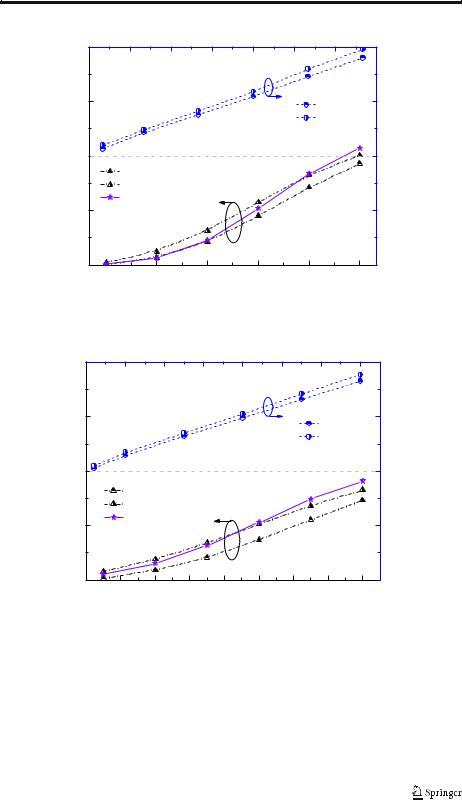
Fig. 2 Coupling coefficients of three coupling structures versus the widths (w) and heights (h) at a W-band and b WR-3 band
shown in Fig. 1. The width and thickness of the magnetic coupling window are w and g, as well as the height of the electric coupling gap is h.
The coupling coefficients of such three coupling constructions (including two magnetic coupling ways and one electric coupling) in W-band are calculated by using the full-wave numerical method and compared in Fig. 2a. It is clear that the strong coupling coefficients of

Journal of Infrared, Millimeter, and Terahertz Waves
Fig. 3 Geometric configuration of proposed fifth-order filter at W-band
the offset-coupling construction at W-band are between the ones of magnetic coupling constructions with the 0.2-mm and 0.4-mm thick irises. The H-plane irises at the traditional filter will be scaled to g/3 when working at WR-3 band, which would increase the fabrication difficulty. As shown in Fig. 1(b), when scaling this offset magnetic coupling structure to the higher terahertz frequencies such as the WR-3 band, such coupling will be comparable to the H-plane magnetic coupling with about 0.1-mm-thick irises.
All of the above results have made clear that the offset-coupling construction with a wide window has strong coupling for the wideband filter, especially for the WR-3 and above band waveguide BPFs. In addition, the offset-coupling structure without the thin iris (g) can reduce the machining and assembling difficulty when scaled to higher THz frequency band effectively.
3 Filter Design
A W-band waveguide bandpass filter with 3-dB FBW of 20% is presented based on the above analysis, by using the coupling matrix synthesis method in [9]. Figure 3 exhibits the geometric
Fig. 4 Photographs of the
fabricated upper and bottom Upper Block blocks
Bottom Block