

диафрагмированные волноводные фильтры / 1df92ff2-e2bf-4763-951e-1d55d7abdaf9
.pdfIEEE TRANSACTIONS ON MICROWAVE THEORY AND TECHNIQUES, VOL. 53, NO. 3, MARCH 2005 |
843 |
Novel E-Plane Filters and Diplexers With Elliptic Response for Millimeter-Wave Applications
Erdem Ofli, Member, IEEE, Rüdiger Vahldieck, Fellow, IEEE, and Smain Amari, Member, IEEE
Abstract—A new class of  -plane filters based on cross-coupled resonators or over-moded cavities is introduced. The filters exhibit pseduoelliptic transfer functions with steep attenuation slopes. The metal inserts and separating wall between waveguide sections can be fabricated using electro-deposition techniques with the accuracy required for millimeter-wave applications. The filters are mass-producible, are much shorter than traditional
  -plane filters, and have less insertion loss. Based on this new type of
  -plane filter, highly compact diplexer structures are designed. A comparison between prototype filters and design prediction shows excellent agreement.
Index Terms—Diplexers, elliptic filters,  -plane filters, waveguide filters.
I. INTRODUCTION
Fig. 1. Cross-coupled folded E-plane metal-insert filter structure with source– load coupling (four resonators).
FOR OVER 20 years,  -plane filters have been known as a cost-effective solution for low-to-moderate filter requirements. Their ease of manufacturing and the availability of accurate design software have made direct-coupled
  -plane filters the structure of choice for many applications in the frequency range from 10 to 150 GHz (e.g., [1]–[4]). The electrical performance of
  -plane filters is mainly determined by the pattern of the metal inserts. Keeping those thin enough, say, between 30–100
  m, the pattern can be fabricated with high precision
using photolithographic or electro-deposition techniques.
A commonly known disadvantage of direct-coupled  -plane filters is that, for a given number of resonators, the attenuation slopes are relatively moderate. Steeper attenuation slopes are feasible only by adding more resonators, thus, also adding insertion loss and increasing the filter length. To avoid these disadvantages, but maintain the advantage of ease of fabrication of
  -plane filters, an alternative approach was suggested in [5]. By placing inductively coupled stopband stubs, the attenuation slope could be improved. The drawback of this solution is, however, that the waveguide split-block housing to clamp the metal insert became larger in size.
This paper introduces yet another technique to improve the slope selectivity of  -plane filters without increasing the number of resonators. This solution is based on the well-known technique of cross-coupling of resonators [6], [7], which, except in [8], has never been applied to
  -plane filters. Cross-coupling
Manuscript received March 9, 2004; revised November 1, 2004.
E. Ofli and R. Vahldieck are with the Laboratory for Electromagnetic Fields and Microwave Electronics, Swiss Federal Institute of Technology, CH-8092 Zurich, Switzerland (e-mail: vah@ifh.ee.ethz.ch).
S. Amari is with the Department of Electrical and Computer Engineering, Royal Military College of Canada, Kingston, ON, Canada K7K 7B4 (e-mail: Smain.Amari@rmc.ca).
Digital Object Identifier 10.1109/TMTT.2004.842506
between resonators generates transmission zeros at finite frequencies resulting in pseduoelliptic filter functions. As shown in the following, this technique allows very compact filter and diplexer designs based on  -plane technology.
II. CROSS-COUPLED  -PLANE FILTERS
The basic  -plane structure that allows the realization of pseduoelliptic filter functions is shown in Fig. 1. The sketch shows a fourth-order
  -plane filter, which is folded between the second and third resonators. In this case, the source and load are coupled through a slot in the common wall separating both filter halves. The height of the slot is commensurate with the waveguide height and, thus, exciting only


 modes. Cross-cou- plings between the resonators and the source and load lead to
  transmission zeros

 number of resonators
 at finite frequencies. The computed filter response of the source–load coupled
  -plane filter is shown in Fig. 2 [8]. For comparison, the same figure illustrates the response from a traditional
  -plane filter. Five finite transmission zeros are obtained with this configuration. Four of those are due to the source–load coupling and cross-coupling between resonators. The additional zero can be explained by the frequency dependence of the coupling coefficients, especially those implementing the cross-coupling between the source and load and resonators 1 and 4, respectively. In fact, it is possible to generate finite transmission zeros even in direct-coupled resonator filters if the coupling coefficients are strongly dispersive [9]. The simulation of the cross-cou- pled structure is based on a


 -mode approach using the mode-matching technique (MMT).
For the successful implementation of transmission zeros with cross-coupled resonators, shown in Fig. 1, it is important that both negative and positive coupling coefficients can be realized
0018-9480/$20.00 © 2005 IEEE

844 |
IEEE TRANSACTIONS ON MICROWAVE THEORY AND TECHNIQUES, VOL. 53, NO. 3, MARCH 2005 |
Fig. 2. Response of the cross-coupled folded E-plane metal-insert filter with source–load coupling (solid line) and straight E-plane single metal-insert filter (dashed line) with four resonators.
utilizing only magnetic coupling. If the source (besides its coupling to the load, Fig. 1) is coupled only to resonator 1 and the load only to resonator 4, then the coupling between resonators 1 and 4 must be negative in order to generate two transmission zeros on the imaginary axis of the complex  -plane [10]. More precisely, the product of the three direct couplings and cross-coupling must be negative. This is not possible in an
  -plane structure if only the fundamental resonance


 is used in all resonators. In this case, the cross-coupling would be positive thereby placing the transmission zeros onto the real axis in the complex
  -plane. To achieve negative coupling between source and load, a


 resonance is excited in resonator 3 only. By placing the coupling slot between resonators 2 and 3 in the second half of resonator 3, the coupling between resonators 1 and 4 becomes negative. This shifting technique is well described in [11].
To design cross-coupled  -plane filters, the first step is to synthesize a low-pass prototype, which fits the specifications and determine the appropriate coupling matrix. A synthesis technique of canonical filters with source–load coupling was developed by Bell [12]. A more recent technique suggests that filters with source–load coupling of orders higher than two are practically unrealizable given the large numerical differences between the entries of their coupling matrices [13]. The discussion in [13] overlooks, however, that a more useful solution of the coupling matrix exists and that the coupling coefficients can indeed be easily implemented for filters of any order. This was shown in [14].
From the synthesis of a pseduoelliptic filter, the target function is known. What follows is an electromagnetic (EM)-based optimization approach to find the optimum geometrical structure to match the target response.
Before optimizing the structure, initial starting dimensions for the coupling and resonator sections of a direct-coupled filter are determined following the procedure given in [2]. Subsequently cross-coupling is introduced for which the size and location of the opening in the separating wall coupling resonators 1 and 4 are approximately determined. To do so, the coupled
Fig. 3. Coupling coefficient values versus: (a) iris width (l ) and (b) iris thickness of the coupled resonator structure.
resonator structure (resonators 1 and 4) is analyzed as sketched in Fig. 3(a) and their resonant frequencies  and
and  are found using the MMT. The coupling coefficient between both resonators (
 ) is then calculated as [15]
(1)
Fig. 3(a) and (b) shows the coupling coefficient versus the width and thickness of the coupling iris, respectively. Enlarging the iris width or reducing the iris thickness increases the coupling value.
Note that the height of the coupling slot is the same as the waveguide height in order not to complicate the computation. The opening size of the coupling slot and the lengths of resonators 1 and 4 are obtained by equating the value obtained from
(1) to the corresponding entry in the coupling matrix. A similar procedure is applied to find the opening size between the second and third resonators (Fig. 1), except that now nonidentical cavities are considered. To illustrate the results of this initial design,
OFLI et al.: NOVEL -PLANE FILTERS AND DIPLEXERS WITH ELLIPTIC RESPONSE FOR MILLIMETER-WAVE APPLICATIONS |
845 |
Fig. 4. Computed response of the filter before optimization (dashed line), after optimization (solid line) and ideal response of the prototype filter (dotted line).
the response of a four-resonator filter with cross-coupling between the first and fourth resonators is plotted in Fig. 4. The dotted line in the same figure shows the ideal response of the prototype filter.
Starting with these initial dimensions, the structure is optimized using a hybrid optimization technique based on a surrogate model [16]. For the example in Fig. 4, the sensitivities of the filter parameters [frequency shift of each single resonator with respect to the center frequency 


 , input and output couplings


 m and coupling coefficients between resonators
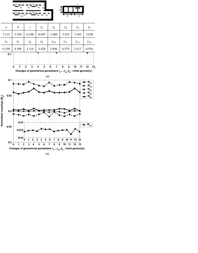
 (direct and cross couplings)] with respect to the geometrical parameters (position and size of resonators, septa, and coupling slots in the separating wall) are computed. The resonant frequency shifts and the variations of coupling coefficients versus geometrical changes are shown in Fig. 5(a) and (b), respectively. The change in one dimension mainly changes the frequency and coupling parameter associated with the closest resonator. However, depending on the loading, slight changes also occur in neighboring resonators and respective coupling coefficients. The solid line in Fig. 4 shows the optimum response of the filter after 600 optimization steps (in the model space) and only 13 EM simulations. The optimized filter dimensions are shown in Table I.
In the following, all filters are designed on the basis of the above procedure.
A. Advantages and Disadvantages of Filters With
Source–Load Coupling
Filters with source/load-multiresonator coupling show significantly improved slope selectivity compared to standard all-pole  -plane filters with the same number of resonators. Fig. 6 shows the performances of three four-resonator filters of the same center frequency and bandwidth: a direct-coupled filter (solid line) and a cross-coupled filter with (dotted line) and without (dashed line) source–load coupling. A comparison of the asymmetric response of the cross-coupled filter with source–load coupling that of a cross-coupled filter without source–load coupling demonstrates further improvement in the stopband.
Fig. 5. Sensitivities of: (a) normalized frequency shifts and (b) normalized coupling coefficients with respect to geometrical changes (1: l +1l, 2: l
 +1l, 3: l
 + 1l; . . . ; 1l = 10 m).
TABLE I
DATA FOR Ka-BAND CROSS-COUPLED FOLDED E-PLANE
METAL-INSERT FILTER (IN MILLIMETERS)
The main advantage of these filters is that they allow better control of the stopbands since they can implement up to  finite transmission zeros (in a filter of order
  ) instead of only

 when the source and load are coupled to only one resonator each. The additional two transmission zeros can be used to either
846 |
IEEE TRANSACTIONS ON MICROWAVE THEORY AND TECHNIQUES, VOL. 53, NO. 3, MARCH 2005 |
Fig. 6. Response of three four-resonator filters: direct-coupled filter (solid line) and cross-coupled filter with (dotted line) and without (dashed line) source–load coupling.
Fig. 7. Response of the cross-coupled folded E-plane metal-insert filter (solid line) and straight E-plane single metal-insert filter (dashed line) with four resonators.
improve the stopband or the group delay. The positions of the transmission zeros are very sensitive to small changes in the dimensions of the slot between source and load, which makes these filters sensitive to manufacturing tolerances.
B. Four-Resonator Cross-Coupled Filter
Fig. 7 shows a four-resonator filter structure with a crosscoupling between resonators 1 and 4. The in-band return loss is 20 dB with a center frequency of 30.25 GHz and a bandwidth of 500 MHz. The two finite transmission zeros are located at 29.50 and 31.00 GHz. The coupling matrix of this filter is given as
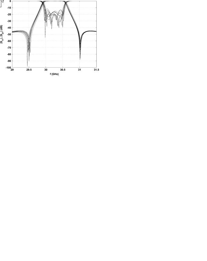
Fig. 8. Tolerance analysis (610 m) of the filter of Fig. 7.
(2)
To implement the negative coupling coefficient between resonators 1 and 4, the 


 -mode resonance is used in resonator 3. All other resonators are based on the


 resonance. The response of the filter is compared with that of an ordinary
  -plane filter with the same number of resonators (Fig. 7). The dramatic improvement due to the two finite transmission zeros (solid line) in the cutoff slope is evident.
Several response simulations of the filter were obtained applying random variations to the geometrical dimensions of the structure, as shown in Fig. 8. The analysis indicates that the waveguide width and insert dimensions must stay within  10
10  m of their nominal values to achieve repeatable results over a large number of samples, which is compatible with the tolerance requirements for direct-coupled filters. This accuracy for the metal inserts can easily be achieved, also in mass
production, using an electro-deposition/plating technique.
C. Four-Resonator Cross-Coupled Filter With
Asymmetric Response
An asymmetric filter response with a steeper attenuation slope either on the leftor right-hand side from the passband can be quite useful for a number of applications. To achieve such a response with a cross-coupled  -plane filter requires the coupling of resonators 1 and 4 via evanescent modes and resonators 1 and 3 via the fundamental mode. The corresponding coupling matrix is the following:
(3)
This is demonstrated in Fig. 9. This figure shows a comparison between the MMT and, for verification, a finite-ele-

OFLI et al.: NOVEL -PLANE FILTERS AND DIPLEXERS WITH ELLIPTIC RESPONSE FOR MILLIMETER-WAVE APPLICATIONS |
847 |
Fig. 9. (a) Structure of a cross-coupled folded E-plane metal-insert filter with four resonators (cross-coupling between first and third resonators). (b) Response of the filter by MMT (solid line) and HFSS (dashed line).
ment analysis (HFSS). Both simulations are in good agreement. The transmission zero on the left-hand side of the passband can be independently shifted closer to the passband by placing the septum (between resonators 3 and 4) closer to the coupling slot (between resonators 1 and 3). The position of the shorting wall (resonator 3) strongly affects the position of the transmission zero in the higher stopband. To shift both zeros at the same time, one has to change the dimension of the coupling slot between resonators 1 and 3.
D. Four-Resonator Cross-Coupled Filter With
Waveguide Bends
The input and output waveguides of the original cross-cou- pled  -plane filter (Fig. 7) are on the same side and are separated by only a 100-
 m-thick separating wall. With this configuration, it is not possible to connect standard waveguide adaptors to the input and output of the filter. One solution is to add 90
 -plane bends in front and behind the filter, as shown in Fig. 10. For optimum filter design, the dimensions of the bends must be included in the optimization. The filter of Fig. 10 was fabricated and measured. A photograph of the filter and the metal inserts are shown in Fig. 11(a) and (b). The measured response is shown in Fig. 12, showing excellent agreement with the computed response. It is shown that not only the improvement in the attenuation slope is still maintained, but in addition, the interaction of the bends with the filter results in a better spurious response of the overall structure.
E. Triplet
The structure shown in the inset of Fig. 13 also allows the realization of filter functions with finite transmission zeros. This
Fig. 10. Structure of a cross-coupled folded E-plane metal-insert filter with waveguide bends.
Fig. 11. (a) Cross-coupled folded E-plane metal-insert filter with waveguide bends. (b) Metal inserts.
Fig. 12. Calculated (dashed line) and measured (solid line) response of the filter (Fig. 11) and calculated response of the cross-coupled folded E-plane filter without waveguide bends (dashed–dotted line).
structure contains three resonators that are coupled to the load and the source, but not to each other. Similar structures with two iris-coupled resonators have been introduced and discussed in detail in [17]. The widths of the three waveguide parts are not equal. The dimensions are used to place the transmission zeros according to the application. Such a filter block can be used with other filter blocks to design higher order filters, and for applications where two transmission zeros are required in the immediate vicinity of the passband. The initial design of the filter is found by following the procedure outlined in [17]. The performance of the filter is illustrated in Fig. 13. The dashed line shows the initial response. The presence of three separate paths for the signal provides two transmission zeros at both sides of the passband. In order to achieve destructive interference between the paths, one 


 cavity and two


 cavities are employed.

848 |
IEEE TRANSACTIONS ON MICROWAVE THEORY AND TECHNIQUES, VOL. 53, NO. 3, MARCH 2005 |
Fig. 13. Computed response of the triplet (inset) before optimization (dashed line) and after optimization (solid line).
Fig. 14. Direct-coupled E-plane metal-insert filter structure with over-moded cavity (four resonators).
III.  -PLANE FILTERS WITH OVER-MODED CAVITIES
In some applications, only one transmission zero either on the leftor right-hand side of the passband is required. This is possible by using dispersive stubs, as suggested in [18] for iriscoupled filters, and later also shown for  -plane filters [19].
The design of  -plane filters with over-moded cavities is also initially based on standard
  -plane filter design to meet given specifications roughly [2]. Here, one assumes all resonators coupled via metal inserts. From this procedure, the coupling coefficient between resonator 2 and the over-moded cavity is approximately known. The same coupling coefficient must now be realized by the slot width in the separating wall coupling resonator 2 into 3 (Fig. 14). To obtain a transmission zero either on the leftor right-hand side from the passband the length of the third resonator is increased until the transmission zero occurs. A transmission zero occurs to the right-hand side of the passband when the coupling slot is placed in the first half of the over-moded cavity (counting from the shorting wall of
  , Fig. 14), and on the left-hand side of the passband when the slot is positioned in the second half of the over-moded cavity.
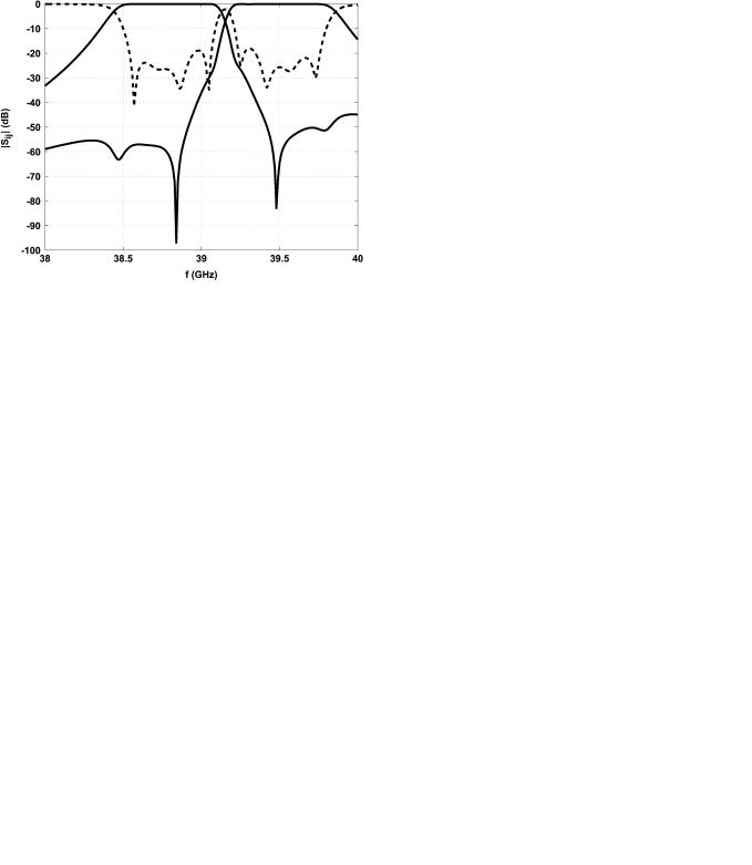
Two design examples for four-resonator filters are given in Fig. 15 with transmission zeros placed on either side of the passband. The in-band return loss in both cases is 23 dB (bandwidth 500 MHz) for center frequencies of 38.8 and 39.5 GHz, respectively. Both filters are used in Section IV in a diplexer application with transmission zeros placed within the guard band.
Fig. 15. (a) Response of a direct-coupled E-plane filter with over-moded cavity and transmission zero on the right-hand side of the passband computed with the MMT (solid line) and verified by HFSS (dashed line). (b) The same as (a), but with transmission zero on the left-hand side of the passband.
The thickness of the metal inserts and the separating wall is chosen to be 100  m (suitable for metal etching or electro-de- position/plating techniques).
The filter of Fig. 15(a) was fabricated and measured to verify the design. The photograph of the filter is shown in Fig. 16(a) and (b); the metal inserts are of 100- m thickness. A comparison between measured and simulated response is given in Fig. 17.
The principle of coupling-resonator sections by over-moded cavities is applied to a direct-coupled ridged waveguide filter, as shown in Fig. 18. The dashed lines in the filter sketch illustrate

OFLI et al.: NOVEL -PLANE FILTERS AND DIPLEXERS WITH ELLIPTIC RESPONSE FOR MILLIMETER-WAVE APPLICATIONS |
849 |
Fig. 16. (a) Direct-coupled E-plane filter with over-moded cavity. (b) Metal inserts.
Fig. 17. Calculated (dashed line) and measured (solid line) response of the filter (Fig. 16).
Fig. 19. Top view of the new diplexer structures: (a) with cross-coupled folded E-plane metal-insert filters and (b) with direct-coupled E-plane metal-insert filters with over-moded cavities.
Fig. 18. Response of the direct-coupled ridged E-plane metal-insert filter structure with an over-moded cavity calculated with HFSS.
the ridged waveguide sections of the structure. Direct coupling between the second and third resonators is achieved by introducing a full-height opening in the separating wall.
An initial design of a direct-coupled ridged  -plane filter with an over-moded cavity is obtained by adjusting the dimensions of the original optimized direct-coupled
  -plane filter shown in Fig. 15(a). The lengths of each coupling septum in the ridged filter are adjusted to obtain the same two-port scattering
parameters as the corresponding septum in the original filter structure without ridged sections at the center frequency of the filter. The lengths of the ridged resonator sections are then calculated using the propagation constants of the fundamental mode in the ridge sections, i.e., making the electrical lengths of resonators in both filters equal. The final dimensions are then found by optimization. A  -band direct-coupled ridged
  -plane filter with an over-moded cavity is shown in Fig. 18. The thickness of the metal inserts and the separating wall is, again, 100
  m. The improvement in the stopband due to the presence of a finite transmission zero at 39.92 GHz is obvious. The resulting filter is more compact than the full-height directcoupled
  -plane filter with an over-moded cavity and has a wider spurious-free range.
IV. MILLIMETER-WAVE DIPLEXER
Both filter structures shown in Figs. 10 and 14 are well suited for compact and high-performance millimeter-wave diplexers [20]. This is shown in Fig. 19(a) where two cross-coupled folded  -plane filters (Fig. 10) are combined with a tapered broadband
  -plane power divider. Fig. 19(b) illustrates a diplexer composed of an
  -plane T-junction with a metal slab and two
  -plane filters with over-moded cavities (Fig. 14).
850 |
IEEE TRANSACTIONS ON MICROWAVE THEORY AND TECHNIQUES, VOL. 53, NO. 3, MARCH 2005 |
Fig. 20. Response of the diplexer of Fig. 19(a) computed with the MMT (solid line) and verified by HFSS (dashed line).
The initial design and optimization of the channel filters, the  -plane transformer [21], and the
  -plane T-junction [22] is done separately. In a final optimization run, the entire structure is fine tuned to account for the interaction effects at the various interfaces. For the structure in Fig. 19(a), the cross-coupled folded
  -plane filters from Fig. 10 are utilized. In particular, the following dimensions are subject to optimization: taper dimensions like the individual waveguide widths


 and lengths


 , the distance between the bifurcation [
 , Fig. 19(a)] and the taper, the distance between the filters and the start of the bifurcation [


 , Fig. 19(a)], and the first septum of the individual filters [

 , Fig. 19(a)]. Other dimensions of the filters remain unchanged throughout the optimization.
The overall structure is analyzed and optimized by using the MMT. The performance of the entire diplexer is illustrated in Fig. 20. The dashed line in the same figure shows the response obtained by an HFSS analysis to verify the MMT results. The agreement between both simulations is very good. It should be noted that due to long CPU run times, the optimization could not be done directly with HFSS, which requires over 90 000 tetrahedras to discretize the entire structure.
Following the same procedure as in the previous diplexer design, another compact diplexer is designed using two direct-cou- pled  -plane filters with only one transmission zero each [see Fig. 19(b)]. The channel filters are designed and pre-optimized such that the attenuation poles provided by each filter are placed in the guard band to improve the isolation between the two channels. The lengths
 and
and 
 , as well as the dimensions of the
 -plane T-junction [
 and
and  , Fig. 19(b)] were optimized to compensate for the mutual loading effect between the filters and to ensure a good match between the input and output waveguides. The lengths of the first septa of the individual filters [
 and
and  , Fig. 19(b)] are also included in the optimization. Fig. 21 shows the performance of the entire diplexer structure after optimization. The return loss is better than 15 dB in the passbands of the channels and can be improved further by including the other dimensions of the filters as independent variables in the optimization.
Fig. 21. Response of the diplexer of Fig. 19(b) computed with the MMT.
V. CONCLUSION
Novel  -plane metal-insert filters and diplexers based on cross-coupled resonators or over-moded cavities have been introduced. These structures are suitable for application in broadband millimeter-wave links as low-cost, high-performance, and compact components. Utilizing source–load coupling, over-moded cavities or combinations thereof leads to a highly flexible class of filter structures suitable for applications in the frequency range from 10 to 100 GHz. Experimental filters have been fabricated and tested. Measured results are in good agreement with computed results.
REFERENCES
[1]R. Vahldieck, J. Bornemann, F. Arndt, and D. Grauerholz, “Optimized waveguide E-plane metal insert filters for millimeter wave applications,” IEEE Trans. Microw. Theory Tech., vol. MTT-31, no. 1, pp. 65–69, Jan. 1983.
[2]Y. C. Shih, “Design of waveguide E-plane filters with all-metal inserts,”
IEEE Trans. Microw. Theory Tech., vol. MTT-32, no. 7, pp. 695–704, Jul. 1984.
[3]L. Q. Bui, D. Ball, and T. Itoh, “Broad-band millimeter-wave E-plane bandpass filters,” IEEE Trans. Microw. Theory Tech., vol. MTT-32, no. 12, pp. 1655–1658, Dec. 1984.
[4]R. Vahldieck and W. J. Hoefer, “Finline and metal insert filters with improved passband separation and increased stopband attenuation,” IEEE Trans. Microw. Theory Tech., vol. MTT-33, no. 12, pp. 1333–1339, Dec. 1985.
[5]J. Bornemann, “Selectivity-improved E-plane filter for millimeter-wave applications,” Electron. Lett., vol. 27, no. 21, pp. 1891–1893, 1991.
[6]A. E. Atia and A. E. Williams, “Nonminimum-phase optimum-ampli- tude bandpass waveguide filters,” IEEE Trans. Microw. Theory Tech., vol. MTT-22, no. 4, pp. 425–431, Apr. 1974.
[7]S. Amari and J. Bornemann, “CIET-analysis and design of folded asymmetric H-plane waveguide filters with source–load coupling,” in Proc. 30th Eur. Microwave Conf., Paris, France, Oct. 2000, pp. 270–273.
[8]E. Ofli, R. Vahldieck, and S. Amari, “Analysis and design of mass-pro- ducible cross-coupled, folded E-plane filters,” in IEEE MTT-S Int. Microwave Symp. Dig., Phoenix, AZ, May 2001, pp. 1775–1778.
[9]S. Amari and J. Bornemann, “Using frequency-dependent coupling to generate finite attenuation poles in direct-coupled resonator bandpass filters,” IEEE Microw. Guided Wave Lett., vol. 9, no. 10, pp. 404–406, Oct. 1999.
[10]A. E. Williams, “A four-cavity elliptic waveguide filter,” IEEE Trans. Microw. Theory Tech., vol. MTT-18, no. 12, pp. 1109–1114, Dec. 1970.

OFLI et al.: NOVEL -PLANE FILTERS AND DIPLEXERS WITH ELLIPTIC RESPONSE FOR MILLIMETER-WAVE APPLICATIONS |
851 |
[11]U. Rosenberg, “New planar waveguide cavity elliptic function filters,” in Proc. 25th Eur. Microwave Conf., Bologna, Italy, Sep. 1995, pp. 524–527.
[12]H. C. Bell, Jr., “Canonical lowpass prototype network for symmetric coupled-resonator bandpass filters,” Electron. Lett., vol. 10, no. 13, pp. 265–266, 1974.
[13]J. R. Montejo-Garai, “Synthesis of N-even order symmetric filters with N transmission zeros by means of source–load cross-coupling,” Electron. Lett., vol. 36, no. 3, pp. 232–233, 2000.
[14]S. Amari, “Direct synthesis of folded symmetric resonator filters with source–load coupling,” IEEE Microw. Wireless Compon. Lett., vol. 11, no. 6, pp. 264–266, Jun. 2001.
[15]K. R. Sturley, Radio Receiver Design. London, U.K.: Chapman & Hall, 1945, ch. 7.
[16]P. Harscher, E. Ofli, R. Vahldieck, and S. Amari, “EM-simulator based parameter extraction and optimization technique for microwave and millimeter wave filters,” in IEEE MTT-S Int. Microwave Symp. Dig., Seattle, WA, Jun. 2002, pp. 1113–1116.
[17]S. Amari and U. Rosenberg, “The doublet: A new building block for modular design of elliptic filters,” in Proc. 32th Eur. Microwave Conf., Milan, Italy, Sep. 2002, pp. 405–407.
[18]W. Menzel, F. Alessandri, A. Plattner, and J. Bornemann, “Planar integrated waveguide diplexer for low-loss millimeter wave applications,” in Proc. 27th Eur. Microwave Conf., Jerusalem, Israel, Sep. 1997, pp. 676–680.
[19]E. Ofli, R. Vahldieck, and S. Amari, “Compact E-plane and ridge waveguide filters/diplexers with pseudo-elliptic response,” in IEEE MTT-S Int. Microwave Symp. Dig., Philadelphia, PA, Jun. 2003, pp. 949–952.
[20], “A novel compact millimeter-wave diplexer,” in IEEE MTT-S Int. Microwave Symp. Dig., Seattle, WA, Jun. 2002, pp. 377–380.
[21]J. Bornemann, “Design of millimeter-wave diplexers with optimized H-plane transformer sections,” Can. J. Elect. Comput. Eng., vol. 15, no. 3, pp. 5–8, 1990.
[22]Y. Rong, H. Yao, K. A. Zaki, and T. Dolan, “Millimeter-wave Ka-band H-plane diplexers and multiplexers,” IEEE Trans. Microw. Theory Tech., vol. 47, no. 12, pp. 2325–2330, Dec. 1999.
Erdem Ofli (M’02) received the B.Sc. and M.Sc. degrees in electrical engineering from Bilkent University, Ankara, Turkey, in 1995 and 1997, respectively, and the Ph.D. degree in electrical engineering from Swiss Federal Institute of Technology (ETH) Zürich, Zürich, Switzerland, in 2004.
His research interests include microwave and millimeter-wave components and systems design and numerical techniques in electromagnetics.
Rüdiger Vahldieck (M’85–SM’86–F’99) received the Dipl.-Ing. and Dr.-Ing. degrees in electrical engineering from the University of Bremen, Bremen, Germany, in 1980 and 1983, respectively.
From 1984 to 1986, he was a Post-Doctoral Fellow with the University of Ottawa, Ottawa, ON, Canada. In 1986, he joined the Department of Electrical and Computer Engineering, University of Victoria, Victoria, BC, Canada, where he became a Full Professor in 1991. During the fall of 1992 and the spring of 1993, he was a Visiting Scientist with
the Ferdinand-Braun-Institute für Hochfrequenztechnik, Berlin, Germany. In 1997, he accepted an appointment as a Professor of EM-field theory with the Swiss Federal Institute of Technology (ETH) Zürich, Zürich, Switzerland, and became Head of the Laboratory for Electromagnetic Fields and Microwave Electronics (IFH) in 2003. His research interests include computational electromagnetics in the general area of electromagnetic compatibility (EMC) and, in particular, for computer-aided design of microwave, millimeter-wave, and opto-electronic integrated circuits. Since 1981, he has authored or coauthored over 230 technical papers in books, journals, and conferences, mainly in the field of microwave computer-aided design.
Prof. Vahldieck is the past president of the IEEE 2000 International Zürich Seminar on Broadband Communications (IZS’2000). Since 2003, he has been president and general chairman of the International Zürich Symposium on Electromagnetic Compatibility. He is a member of the Editorial Board of the IEEE TRANSACTIONS ON MICROWAVE THEORY AND TECHNIQUES. From 2000 to 2003, he was an associate editor for the IEEE MICROWAVE AND WIRELESS COMPONENTS LETTERS, and in January 2004, he became the editor-in-chief. Since 1992, he has served on the Technical Program Committee (TPC) of the IEEE Microwave Theory and Techniques Society (IEEE MTT-S) International Microwave Symposium (IMS), the IEEE MTT-S Technical Committee on Microwave Field Theory, and in 1999, on the TPC of the European Microwave Conference. From 1998 to 2003, he was the chapter chairman of the IEEE Swiss Joint Chapter on Microwave Theory and Techniques, Antennas and Propagation, and EMC. Since 2005, he has been president of the Research Foundation for Mobile Communications. He was the recipient of the J. K. Mitra Award of the Institution of Electronics and Telecommunication Engineers (IETE) (in 1996) for the best research paper in 1995 and was corecipient of the Outstanding Publication Award of the Institution of Electronic and Radio Engineers in 1983.
Smain Amari (M’98) received the DES degree in physics and electronics from Constantine University, Constantine, Algeria, in 1985, and the Masters degree in electrical engineering and Ph.D. degree in physics from Washington University, St. Louis, MO, in 1989 and 1994, respectively.
From 1994 to 2000, he was with the Department of Electrical and Computer Engineering, University of Victoria, Victoria, BC, Canada. From 1997 to 1999, he was a Visiting Scientist with the Swiss Federal Institute of Technology, Zürich, Switzerland, and a
Visiting Professor in Summer 2001. Since November 2000, he has been with the Department of Electrical and Computer Engineering, Royal Military College of Canada, Kingston, ON, Canada, where he is currently an Associate Professor. He is interested in numerical analysis, numerical techniques in electromagnetics, applied physics, applied mathematics, wireless and optical communications, computer-aided design (CAD) of microwave components, and application of quantum field theory in quantum many-particle systems.