

диафрагмированные волноводные фильтры / fbbfeabb-656f-4ddc-9042-c97c2d6a8c1d
.pdfEnhanced Waveguide Bandpass Filters Using
S-Shaped Resonators
N. Suntheralingam, D. Budimir
Wireless Communications Research Group, Department of Electronic, Communication and Software Engineering, University of Westminster, London W1W 6UW, United Kingdom
Received 12 September 2008; accepted 15 December 2008
ABSTRACT: This article presents a new solution for stopband performance improvement of rectangular waveguide bandpass filters using S-shaped resonator loaded waveguide configurations at microwave and millimeter-wave frequencies. The proposed filter structure is compact in size when comparing with the standard E-plane counterpart. Compactness is achieved by taking advantage of the properties of slow wave effect in half wavelength resonators. Periodicity is readily imposed upon cascading the S-shaped resonators within the rectangular waveguide. The structure is simple and compatible with E-plane technology. This type of bandpass filters can be easily realized with a single metallo-dielectric insert within a standard rectangular waveguide. Simulation and experimental results are presented to validate the argument along with some design guidelines.
Int J RF and Microwave CAE 19: 627–633, 2009.
Keywords: rectangular waveguides; S-shaped resonators; waveguide bandpass filters; periodic structures
I. INTRODUCTION
Modern wireless and satellite communications systems require low cost, mass producible, and low dissipation loss microwave and millimetre-wave components such as filters, diplexers, and multiplexers [1–3]. The fast growth in commercial interest in microwave and millimeter wave systems has provided a significant challenge to conventional microwave filter and their design methodologies. High-per- formance bandpass filters having a low-insertion loss, compact size, wide stopband and a high selectivity are important for next-generation wireless and satellite communications systems. Over the past few deca-
Correspondence to: D. Budimir; e-mail: d.budimir@westminster. ac.uk
DOI 10.1002/mmce.20373
Published online 7 August 2009 in Wiley InterScience (www. interscience.wiley.com).
des, all-metal inserts placed in the E-plane of a rectangular waveguide have been a sustainable solution for robust, low-cost, mass producible, low-loss and high-power filters at microwave and millimeter-wave frequencies [4]. However, despite their favorable performances, the attenuation in the second stopband may often be too low and too narrow for diplexer and multiplexer applications.
In recent years, a number of approaches have been proposed to improve stopband performance of rectangular waveguide bandpass filters [5–10]. The MIT group [11, 12] has proposed the S-shaped resonators. In [13], we investigated a new class of rectangular waveguide resonator structure using S-shaped resonators. By employing S-shaped resonators, we are changing the cutoff frequency of a conventional rectangular waveguide resonator and achieving a higher loaded Q with shorter resonator length. This is due to the slow-wave effect; the phase velocity and the guided wavelength of the slow wave are significantly
VC 2009 Wiley Periodicals, Inc.
627
628 Suntheralingam and Budimir
reduced relative to those of a wave propagating in a comparable homogeneous resonator structures. Hence, the length of a half wavelength resonator is accordingly reduced. This article therefore extends the work in [13] by proposing the replacement of the homogeneous resonator sections of E-plane rectangular waveguide bandpass filter with the S-shaped resonators. The proposed miniaturised waveguide bandpass filter structure is a combination of metal septa and S-shaped resonators. It maintains low-cost, massproducible charracteristics of E-plane technology while improving the stopband performance.
II. PROPOSED FILTER STRUCTURE
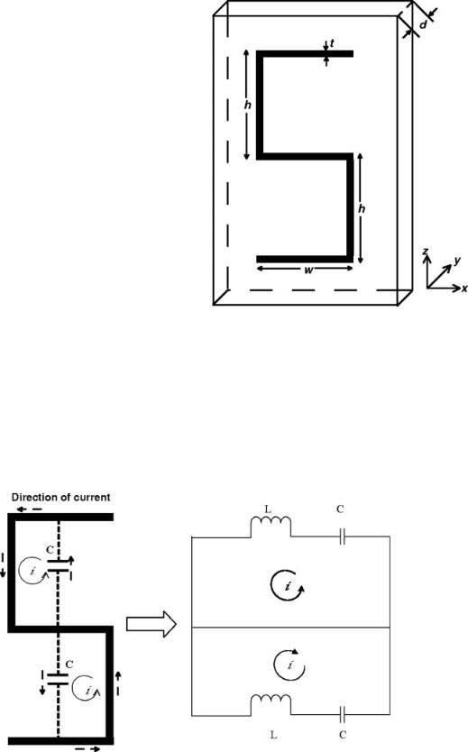
The proposed S-shaped resonator loaded hollow metallic rectangular waveguide bandpass filter structure, for the use at microwave and millimeter wave frequencies, is presented in Figure 1 along with the S-shaped resonator dimensions. Its conventional, E-plane, metal-insert counterpart is shown in Figure 2. The proposed filter structure is designed at X-band with f0 5 9.45 GHz and BW 5 1.2 GHz with an extended stopband to 15 GHz at a rejection level of 15 dB. The S-shaped resonator filter is constructed with a transmission line loaded metallo-dielectric slab, which conveniently facilitate the S-shaped resonator loaded filter with the metal septa. The S-shaped resonators are presented on a single side of the dielectric block. Dielectric substrate of Rogers RT/Duroid 5880 (relative dielectric permittivity er 5 2.2 and thickness t 5 0.508
Figure 1. Unit cell geometry of a single sided S-shaped resonator structure.
mm) has been used to create the slab loading with a metallisation thickness of 0.017 mm. Standard rectangular waveguide of WG-16 has been used as the housing to fit the dielectric slab. Dimensions of the two filters at 9.45 GHz are given in Table I.
Figure 2. Equivalent circuit for the geometry in Figure 1.
International Journal of RF and Microwave Computer-Aided Engineering DOI 10.1002/mmce

TABLE I. Dimensions of the Conventional
and the Proposed S-Shaped Resonator Loaded
Waveguide Filters
|
|
S-Shaped |
|
|
Resonator |
|
Conventional |
Loaded |
Parameters (mm) |
WG Filter |
WG Filter |
|
|
|
WG inner dimensions |
22.86 3 10.16 |
22.86 3 10.16 |
(WG16) |
|
|
Total structure length (l) |
50 |
51 |
Dielectric slab length |
– |
51 |
Dielectric thickness |
– |
0.51 |
Metal septa length |
1.2, 3, 1.2 |
1.2, 3, 1.2 |
lres |
17.8 |
14 |
Metallization thickness |
0.1 |
0.017 |
Distance between the |
– |
1 |
two S-shaped |
|
|
resonators on the side |
|
|
|
|
|
III. THEORETICAL AND NUMERICAL CONSIDERATIONS
Figure 3 shows a single sided S-shaped resonator loaded unit cell structure used for the proposed filter. The equivalent circuit for geometry in Figure 3 is presented in Figure 4. When a magnetic field is applied, the two gap capacitances C between the metallic strips enable the induced current which flow around the S-shaped resonator. Inductance L of each half ring is directly proportional to the area enclosed by the ring [12] and can be expressed by,
Figure 3. Variation of filter performance with and without the S-shaped resonators in the resonator section.
Enhanced Waveguide Bandpass Filters |
629 |
Figure 4. Variation of filter performance with and without the pairs of S-shaped resonators at the beginning and end of the filter structure.
|
¼ l0 |
2 |
|
2 |
l0 2 |
ð |
Þ |
|
L |
|
w t |
|
2h 3t |
|
hw |
1 |
|
|
|
|
|
|
|
|
||
Applying circuit theory, a magnetic resonant frequency of the unit cell structure can be found from,
s |
r |
|
|||||
ð |
Þð |
Þ |
|
|
|||
xm0 |
|
1 |
|
¼ |
1 |
|
ð2Þ |
|
2L C2 |
|
LC |
||||
Figure 5. Variation of passband with variable S-shaped resonator height ‘‘h.’’
International Journal of RF and Microwave Computer-Aided Engineering DOI 10.1002/mmce

630 Suntheralingam and Budimir
Figure 6. Retrieved index of refraction versus frequency of the designed filter.
Simulation of the proposed structure has been carried out in order to obtain some physical insight and design guidelines. The mode matching method with 60 modes has been used for the electromagnetic analysis of the conventional E-plane waveguide filter structure [14] while the finite element method (HFSSTM) [15] has been used for the proposed S- shaped resonator filter. Both methods are well established and therefore expressions are not given here.
To provide some insight of how the dimensions of the S-shaped resonators are chosen and to provide some design guidelines along with some numerical examples, we have presented Figure 5 which investigates the effect of the S-shaped resonators in the resonator sections, transfer characteristic variations are shown for both cases (with and without the S-shaped resonators in the resonator section). Figure 6 presents the effect of the pairs of S-shaped resonators at the
Figure 7. Conventional E-plane, two resonator, all- metal-insert rectangular waveguide bandpass filter configuration.
edges of the structure. It is evident from this numerical study that while the pairs of S-shaped resonators at the edges of the structure contribute to the improvement in stopband performance, the S-shaped resonators in the resonator sections can be used to control the resonant frequency. To investigate the effect of the size of S-shaped resonators, it has been designed with different heights h of the structure. Figure 7 shows the variation of responses with heights h at 4.0 mm and 7.2 mm. It is clear from the responses that the passband moves to a lower frequency band with the increase in height h of the S- shaped resonator. This phenomenon can be explained from (2). Inductance L of the S-shaped resonator structure rises with h. This in turn decreases the resonant frequency fres.
To use the advantages of left-handed properties of the S-shaped resonator structure in filter performances, the designed filter has been tuned to realize simultaneously negative permittivity and negative permeability responses at comparable frequencies. Index of refraction n can be found from the simulated reflection and transmission coefficients of a normal incident wave on a slab of the S-shaped resonator loaded structure by applying the parameter retrieval algorithm [12, 16]. In Figure 8, we plotted the retrieved index of refraction versus frequency of the
Figure 8. Proposed S-shaped resonator loaded rectangular waveguide bandpass filter.
International Journal of RF and Microwave Computer-Aided Engineering DOI 10.1002/mmce
Enhanced Waveguide Bandpass Filters |
631 |
S-shaped resonator loaded waveguide filter. The designed filter, which is a combination of S-shaped resonators and metal septa, clearly exhibits that there exist multiple frequency bands where the refraction index is negative. These left-handed passbands are due to the multiple capacitances and inductances induced in the structure.
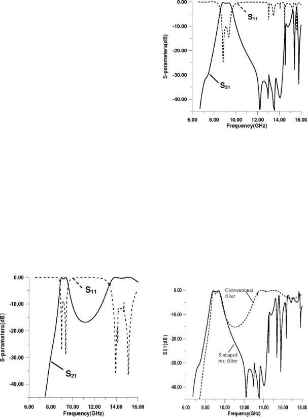
The simulated scattering parameters of the conventional and the proposed S-shaped resonator loaded filter are plotted in Figures 9 and 10, respectively. Figure 11 presents the superposition of both the insertion losses. It is evident from Figure 11 that a good improvement in stopband performance is achieved by employing the S-shaped resonators in this kind of filter.
IV. EXPERIMENTAL RESULTS
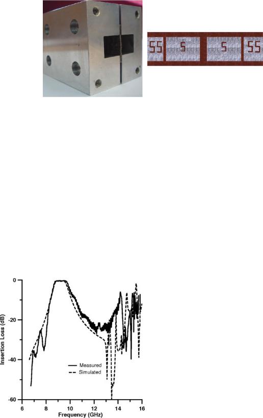
To illustrate the feasibility of the proposed S-shaped resonator loaded waveguide filter structure, it has been fabricated using the standard PCB process at 9.45 GHz. The response of the fabricated filter was measured with Agilent PNA (E8361A) vector network analyzer in our lab. Fabricated prototype of the proposed S-shaped resonator loaded filter while mounted inside the WG16 housing is shown in Figure 12. Simulated and measured insertion losses of the S- shaped resonator filter are presented in Figure 13. The measured response agrees very well with the simulation.
The total length of the fabricated filter is 51 mm. The size reduction of the periodic bandpass filter
Figure 10. Simulated S-parameters of the proposed filter.
derives from two factors; first, the size of half wavelength resonators of a periodic filter is reduced compared with a homogeneous one according to the guided wavelength reduction. Second, the improved selectivity of a periodic filter, due to the dispersion relation of the slow waves, is such that same out of band specifications can be achieved with a lower order periodic filter than a homogeneous filter. To demonstrate the compactness of the proposed structure, a comparison has been made with an equivalent structure containing a standard E-plane bandpass filter. To satisfy the upper stopband specification
Figure 9. Simulated S-parameters of the conventional |
Figure 11. Simulated insertion losses of the conventional |
filter. |
and proposed bandpass filters. |
International Journal of RF and Microwave Computer-Aided Engineering DOI 10.1002/mmce
632 Suntheralingam and Budimir
Figure 12. Fabricated prototype of the S-shaped resonator loaded waveguide bandpass filter. [Color figure can be viewed in the online issue, which is available at www.interscience.wiley.com.]
(15 dB loss at 9.45 GHz), a standard E-plane filter with the same passband and ripple should be of the third order, with a total length of 51 mm. In a similar physical size, the proposed configuration shows significantly improved stopband performance. Alternatively, if we want to suppress the spurious passband of the standard filter with a lowpass configuration and assuming same size for the corresponding lowpass component and same distance between the two components, the total length of an integrated filter with suppressed spurious passband would be 112.50 mm [5, 6]. A size reduction of around 50% is achieved. The proposed structure maintains the low-cost and mass producible characteristics of E-plane filters while achieving significant size reduction.
Figure 13. Simulated and measured insertion losses of the fabricated prototype.
V. CONCLUSION
A novel type of E-Plane hollow metallic rectangular waveguide bandpass filter structure with improved stopband performance using S-shaped resonators has been proposed. This structure can be easily realized with a single metallo-dielectric insert within the rectangular waveguide. The fabricated prototype at X- band proves that it is easily realizable. Simulated and measured insertion losses of this filter demonstrate a very good agreement. This kind of filters can be found in applications particularly in the microwave and millimeter-wave range circuits, e.g. in diplexers and multiplexers.
REFERENCES
1.V.E. Boria and B. Gimeno, Waveguide filters for satellites, IEEE Microwave Mag 8 (2007), 60–70.
2.J. Uher, J. Bornemann, and U. Rosenberg, Waveguide components for antenna Fed systems: Theory and CAD, Chapter 3.4, Artech House, Boston, 1993.
3.I.C. Hunter, L. Billonet, B. Jarry, and P. Guillon, Microwave filters—Applications and technology, IEEE Trans Microwave Theory Tech 50 (2002), 794–805.
4.D. Budimir, Generalized filter design by computer optimization, Artech House, Boston, 1998.
5.D. Budimir, Optimized E-plane bandpass filters with improved stopband performance, IEEE Trans Microwave Theory Tech 45 (1997), 212–220.
6.G. Goussetis and D. Budimir, Compact ridged waveguide filters with improved stopband performance, IEEE MTT-S Int Microwave Symp, Philadelphia, June 8–13, 2003, pp. 953–956.
7.F. Arndt, J. Bornemann, R. Vahldieck, and D. Grauerholz, E-plane integrated circuit filters with improved
International Journal of RF and Microwave Computer-Aided Engineering DOI 10.1002/mmce

stopband attenuation, IEEE Trans Microwave Theory Tech MTT-32 (1984), 1391–1394.
8.R. Vahldieck and W.J.R. Hoefer, Finline and metal insert filters with improved passband separation and increased stopband attenuation, IEEE Trans Microwave Theory Tech MTT-33 (1985), 1333–1339.
9.M. Morelli, I. Hunter, R. Parry, and V. Postoyalko, Stop-band improvement of rectangular waveguide filters using different width resonators: Selection of resonator widths, IEEE MTT-S Int Microwave Symp Dig, Phoenix, AZ, May 2001, pp. 1623–1626.
10.M. Morelli, I. Hunter, R. Parry, and V. Postoyalko, Stopband performance improvement of rectangular waveguide filters using stepped-impedance resonators, IEEE Trans Microwave Theory Tech MTT-50 (2002), 1657–1664.
11.J. Zhang, H. Chen, Y. Luo, L. Shen, L. Ran, and J.A. Kong, Wideband backward coupling based on aniso-
Enhanced Waveguide Bandpass Filters |
633 |
tropic left-handed metamaterial, Appl Phys Lett 90 (2007), 043506. DOI: 10.1063/1.2435323.
12.H. Chen, L. Ran, J. Huangfu, X. Zhang, K. Chen, T. Grzegorczyk, and J.A. Kong, Left-handed material composed of only S-shaped resonators, Phys Rev E 70 (2004), 1–4.
13.D.R. Smith, D.C. Vier, Th. Koschny, and C.M. Soukoulis, Electromagnetic parameter retrieval from inhomogeneous metamaterials, Phys Rev E 71 (2005), 036617-1–036617-11.
14.N. Suntheralingam, A. Shelkovnikov, and D. Budimir, Novel millimetre wave metawaveguide resonators and filters, 37th Eur Microwave Conf, Munich, Germany, October 8–12, 2007.
15.D. Budimir, EPFIL-waveguide E-plane filter design, Software and user manual, Artech House, Boston, 1999.
16.HFSS Reference Manual, Release 11, Ansoft, USA, 2007.
BIOGRAPHIES
Niranchanan Suntheralingam received the B.Sc. Eng. degree in Electrical and Electronic Engineering from the University of Peradeniya, Peradeniya, Sri Lanka and the M.Sc. degree in Mobile and Satellite Communications from the University of Westminster, London, UK in 2002 and 2005, respectively. He is currently completing his Ph.D. in Electronic Engineering
at the University of Westminster. In October 2005, Niran joined the Wireless Communications Research Group, University of Westminster. He is currently involved in the design of metamate- rial-based novel waveguide components for wireless communication systems in the microwave and millimeter-wave regime.
Djuradj Budimir received the Dipl. Ing. and M.Sc. degrees, both in Electronic Engineering from the University of Belgrade, Serbia, and Ph.D. degree in Electronic and Electrical Engineering, University of Leeds, UK. In March l994, he joined the Department of Electronic and Electrical Engineering at Kings College London, University of London. Since January 1997,
he has been with the Department of Electronic, Communication and Software Engineering, University of Westminster. He is now an Associate Professor with the Department of Electronic, Communication and Software Engineering, University of Westminster, London, UK. Dr. Budimir has written over 190 refereed journal, and conference proceeding papers in the field of RF, and microwave circuits. He is author of the book Generalized Filter Design by Computer Optimization (Artech House, 1998) and Software and Users Manual EPFIL-Waveguide E-plane Filter Design
(Artech House, 2000), and a chapter in the ‘‘Encyclopaedia of RF and Microwave Engineering,’’ Wiley, February 2005.
International Journal of RF and Microwave Computer-Aided Engineering DOI 10.1002/mmce