

диафрагмированные волноводные фильтры / f70d4b5b-3dfd-433a-a757-cf1fc3543eb8
.pdfDesign of 83GHz Rectangular Waveguide E-plane Diaphragm Bandpass Filter
Yanqiu Zhang1, Bo Zhang1, Senior Member, IEEE, Haoding Murong2, Jinxiong Xie2, Yong Fan1, Member, IEEE
1 School of Electronic Science and Engineering, University of Electronic Science and Technology of China, Chengdu, 611731.
2 Shenzhen Academy of Inspection and Quarantine, Shenzhen, 518010 Email: bozhang@uestc.edu.cn
Abstract-A bandpass filter based on 83 GHz rectangular waveguide E-plane diaphragm is introduced in this paper. Based on the equivalent circuit and the diaphragm coupling of the rectangular waveguide, the width of the diaphragm and the length of the resonator are quantitatively analyzed to obtain more accurate filter parameters. The center frequency of the waveguide filter is 83 GHz, the bandwidth is about 1 GHz, the return loss in the passband is more than 20 dB after optimizing. The filter can be processed and applied in the engineering works.
Keywords-bandpass filter, rectangular waveguide cavity, millimeter wave, E-plane metal
I.INTRODUCTION
With the development of the communication and radar technology, filters as key microwave radio frequency devices are becoming more and more important, and a filter with high performance is highly desirable. In the millimeter wave system, the common filters are usually formed by microstrip lines, strip lines, and coaxial structures and so on. However, these filters are not easy to meet the performance requirements of low insertion loss and high out-of-band rejection. By contrast, a waveguiding filter is much easier to meet these performance requirements [1]. The traditional waveguide structure filter is usually made of common reactance elements such as metal rods and lateral diaphragms. Due to its complicated structure and difficult debugging, it is not conducive to mass production and cost reduction [2]. The filter realized by the planar circuit can overcome these shortcomings. It has the characteristics of low in-band insertion loss and high out-of-band suppression. Once the E- side circuit (longitudinal diaphragm composition) is accurately designed, the expected performance of the filter can be realized. As a result, it’s quite suitable for mass production due to its simple assembly, good repeatability and easy design with no debugging.
A design method of the waveguide E-plane metal diaphragm band-pass filter is proposed in this paper by analyzing the circuit characteristics of the waveguide E-plane diaphragm, filter prototype, and high drag reduction matching. . Finally, more accurate parameters are obtained by modeling and simulating with full-wave simulation software. Proposed filter prototype can be applied in the actual project.
II. THEORETICAL ANALYSIS
When designing the waveguide E-plane metal diaphragm bandpass filter, the filter order n and low-pass prototype parameters should be determined according to the given frequency band, insertion attenuation, etc. Then an equivalent circuit of the band-pass filter can be proceeded from the lowpass prototype with the inverter through frequency conversion, in which the characteristic impedance of the components and the K-inverter are determined by the structure size of the E- plane waveguide diaphragm [3].
A. Chebyshev response low-pass filter
The attenuation characteristic of the Chebyshev filter is shown in (1), where LA is the ripple coefficient influencing the ripple attenuation in the passband. The general formula of an n-order Chebyshev polynomial can be given by (2) and (3). [4].
L |
=10lg[1+ 2T 2 ( |
)] |
(1) |
||||
A |
n |
|
|||||
|
|
|
|
|
(2) |
||
Tn ( ) = cos(n arccos ) |
|
1 |
|||||
|
|
|
(3) |
||||
Tn ( ) = ch(n arccos ) |
|
1 |
|||||
The smaller the ripple coefficient, the smaller the attenuation of the ripple in the band, but the attenuation outside the band also decreases [1]. Since the attenuation outside the band increases with the increase of the value of n, it is necessary to choose the appropriate n value to reach the design goal. The order of the filter can be determined by the following equations (4)-(6).
|
arch |
|
10LAs /10 |
−1 |
|
||||
|
|
|
|
|
|
|
|
||
n = |
10LAr /10 |
−1 |
(4) |
||||||
|
|||||||||
|
|
|
|
|
|
|
|||
|
|
arch |
s |
|
|
|
|||
|
L |
=10lg[1+ 2T 2 |
|
|
)] |
(5) |
||
|
( |
|||||||
|
As |
|
|
n |
|
s |
|
|
L |
=10lg[1 |
+ 2T 2 |
(1)] = |
10lg(1+ 2 ) |
(6) |
|||
Ar |
|
n |
|
|
|
|
|
|
B. Frequency transformation
The transformation relationship between the lowpass filter and the band-pass filter is discussed in this part. For a filter with a rectangular waveguide structure, the wavelength of the waveguide is usually used as a variable, but in this paper the E-plane metal diaphragm is used to achieve filtering, which is a function of the free-space wavelength, so the frequency can still be used as a variable [4].
978-1-7281-9064-8/20/$31.00 ©2020 IEEE
Authorized licensed use limited to: California State University Fresno. Downloaded on June 20,2021 at 19:25:48 UTC from IEEE Xplore. Restrictions apply.
Using frequency axis corresponding transformation, the band-pass filter is transformed into a low-pass prototype filter, and its frequency transformation formula can be given in (7) and (8) [5].
|
|
|
|
|
|
|
|
|
||
|
= |
0 |
|
( |
|
− |
0 ) |
(7) |
||
|
|
|
|
|||||||
|
|
|
2 − 1 |
0 |
|
|
||||
|
|
|
|
= 1 |
+ 2 |
|
(8) |
|||
|
|
|
0 |
|
2 |
|
|
|
||
|
|
|
|
|
|
|
|
|
||
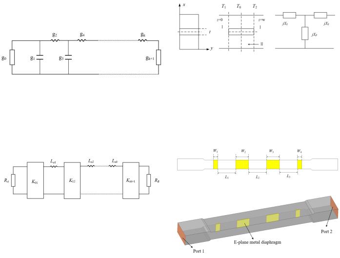
ω1 and ω2 are the lower frequency and upper frequency of the pass band respectively. Through the network synthesis, the prototype circuit of the low-pass filter can be given as shown in Figure 1.
Figure 1. Prototype circuit of low-pass filter
In the microwave filter, since there are multiple inductance and capacitance elements after the frequency conversion, or the parallel and series resonance circuits are connected at one point, the structure is difficult to achieve. As a result, it is necessary to couple the same components in the low-pass prototype through coupling conversion Separate [6]. The socalled deformed low-pass prototype can be get by adding an inverting converter which makes the filter a single-element structuret, as shown in Figure 2 below.
Figure 2. Deformed low-pass prototype filter
C. Analysis of E-plane diaphragm in rectangular waveguide
In the rectangular waveguide, the position of the longitudinal diaphragm and its equivalent network are shown in Figure 3. A metal conductor diaphragm is placed at the center of the waveguide with a length of w, a height of b, and a thickness of t. The discontinuity structure only occurs in the x direction. Since the TE10 is the main mode in the transmission of the waveguide, the TEm0 mode can be excited near the discontinuity while the TEmn (n≠0) mode and the TMmm mode can’t be excited. The diaphragm can be equivalent to a T-shaped network. When the TE10 wave of equal amplitude and opposite phase is incident from the left and right at the same time, the central plane T0 is equivalent to an electrical wall due to the symmetry of the structure. The normalized input admittance is y(1) on the T1 plane. When the TE10 wave of the same phase is incident from the left and the right, the central plane T0 is equivalent to a magnetic wall, and the normalized input admittance is y(2) on the T1 plane [7].
Using the Rayleigh-Ritz method, y(1) and y(2) can be obtained. The equivalent parameters Xs and Xp corresponding to the E- plane can be given by (9) and (10) after substituting the results of y(1) and y(2). [3].
jX s |
1 |
|
|
|
|
(9) |
|||
= |
|
|
|
|
|||||
y(1) |
|
||||||||
|
1 |
1 |
1 |
|
(10) |
||||
jX p = |
|
[ |
|
− |
|
] |
|||
2 |
y(2) |
y(1) |
|||||||
Figure 3. Equivalent diaphragm and equivalent circuit in waveguide
III. DESIGN
The design results of the filter are listed as follows: the center frequency f0 = 83 GHz, the bandwidth Bw= 1 GHz, and the return loss is more than 20 dB by using third-order Chebyshev. In the rectangular waveguide E-plane diaphragm band-pass filter, the resonant circuit of the series branch is realized by a uniform waveguide of certain length. The impedance inversion converter K is implemented by the waveguide E-plane diaphragm [2]. Finally, the schematic diagram of the E-plane diaphragm is shown in Figure 4.
Figure 4. E mask sheet schematic
Figure 5. Rectangular waveguide E-plane metal diaphragm filter model
The difficulty and the focus point of this design is determining the precise values of the E-plane metal diaphragm parameters and filter parameters. The value of W1, W2, W3 and W4 affect the coupling coefficient of the filter while the value of L1, L2 and L3 affect the resonance frequency of the filter. As the diaphragm width increases, the coupling coefficient increases, the resonator length and the resonance frequency decrease. After optimization, the dimensions of the waveguide cavity are 2.56 mm of the wide side and 1.27 mm of the narrow side while W1=0.487 mm, W2=1.435 mm, W3=1.435 mm, W4=0.487 mm, L1=1.983 mm, L2=1.992 mm, L3=1.983
Authorized licensed use limited to: California State University Fresno. Downloaded on June 20,2021 at 19:25:48 UTC from IEEE Xplore. Restrictions apply.
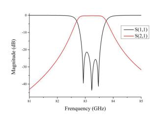
mm, t=0.05 mm. The simulated model is shown in Figure 5, and the simulation results are shown in Figure 6.
Figure 6. Simulated results
IV. CONCLUSION
A 3-order waveguide band-pass E-plane filter is proposed in this paper, which is composed of a cascade of WR-10 band rectangular cavity and the E-plane metal diaphragm. The center frequency is 83 GHz, the return loss is more than 20dB, and the bandwidth is about 1.0 GHz. A filter with high performance can be obtained with the help of adjusting the diaphragm thickness, diaphragm width and resonator length
after optimizing the parameters of the filter. Finally, the results of the simulation show that the engineering requirements are met.
ACKNOWLEDGMENT
Sincerely thank mentor and brother for their hard work and guidance. This work is supported by the National Natural Science Foundation of China (NSFC) under Grant No. 61771116. and No. 91738102.
REFERENCES
[1]M. H. Zhao, Z. R. He, Y. Fan, Y. H. Zhang, “A W-band wideband E- plane type waveguide bandpass filter,” in 2015 8th UK Europe-China Millimeter Waves and THz Technology Workshop, 2015.
[2]R. Nicole, L. Ban, Y. Y. Chen. “Design And Performance of Waveguide E-Plane HTSC insert Filters”, IEEE MTT-S Digest, 1992: 913-915.
[3]D. F. Ji, B. Zhang, Y. Fan, et al, “A novel Waveguide E-plane Filter with metal cut and Loaded cavity,” in Asia-Pacific Microwave Conference (APMC), 2015.
[4]R. Vahldieck and W. J. R. Hoefer, “Finline and Metal Insert Filters with
Improved Passband Separation and Increased Stopband Attenuation,” IEEE Trans. Microw. Theory Tech., vol. MTT-33, no. 12, pp. 1333-1338, Dec. 1985.
[5]F. Arndt, “E-Plane Integrated Circuit Filters with Improved Stopband Attenuation”, IEEE Trans. MTT, 1984, 32(10): 1391-1394.
[6]P. H. Siegel, “Terahertz technology,” IEEE Tans. Microw. Theory Techn.
vol. 50, no. 3, pp. 910-928, Mar. 2002.
[7]Y. N. Feng, B. Zhang, Y. Liu, J. W. Liu, Z. Q. Niu, K. Yang, Y. Fan, X.
D. Chen, “WR-2.8 Band Pseudoelliptic Waveguide Filter Based on Singlet and Extracted Pole” IEEE Access, vol.7, pp. 54705-54711, April 2019.
Authorized licensed use limited to: California State University Fresno. Downloaded on June 20,2021 at 19:25:48 UTC from IEEE Xplore. Restrictions apply.