

диафрагмированные волноводные фильтры / ed634fea-0802-415d-a04b-affadc817be1
.pdfwww.ietdl.org
Published in IET Microwaves, Antennas & Propagation Received on 21st January 2011
Revised on 6th August 2011 doi: 10.1049/iet-map.2011.0261
ISSN 1751-8725
Design of multiple-passband filters using coupling matrix optimisation
X. Shang Y. Wang G.L. Nicholson M.J. Lancaster
School of Electrical, Electonic and Computer Engineering, The University of Birmingham, Edgbaston, Birmingham B15 2TT, UK
E-mail: shangxiaobang@gmail.com
Abstract: This study presents the design of microwave filters based on the coupling matrix approach; determination of the matrix is based on a hybrid optimisation algorithm which may be applied to cross-coupled filters having diverse topologies. Various filter responses from dual-band to quad-band are given as examples of the approach. The optimisation is performed on the coupling matrix and a genetic algorithm (GA) is employed to generate initial values for the control variables for a subsequent local optimisation (sequential quadratic programming search). The novel cost function in this study measures the difference of the frequency locations of reflection and transmission zeros between the response produced by the coupling matrix and the ideal response. The ideal response in the form of characteristic polynomials is determined from the filter specifications and generated by a recently developed iterative technique which is capable of realising multi-band filters with different return loss levels. Convergence of the coupling matrix optimisation is fast, and no initial values for the control parameters are required by the GA. An eighth-order X-band dual-band waveguide filter with all-capacitive-coupling irises has been fabricated and measured to verify the design technique. Excellent agreement between simulation and experimental result has been achieved.
1 Introduction
The design of multiple passband filters has been attracting more attention recently because of their increasing use in modern wireless and satellite systems. Filter synthesis remains an active topic of research, meeting the need for faster and more demanding systems. The cross-coupled filter is a popular choice in order to provide transmission zeros to improve the selectivity. It is also possible to divide the single passband into multi-band (by pure imaginary transmission zeros) and flatten the group delay (by complex transmission zeros). The methods for deriving the coupling matrices have been extensively explored such as [1–17] and these can be classified into two groups: (i) methods based on direct synthesis combined with matrix rotations (i.e. similarity transformations) [7–17] and (ii) methods based on optimisation of the coupling matrix [1–6]. Direct methods for one-step coupling matrix synthesis are available for some special canonical topologies for instance the wheel topologies [7], folded topologies [8], full topologies (i.e. all coupling coefficients are non-zero) [8] and N + 2 transversal network [9]. To achieve cascaded triplets and/or quadruplets from the above canonical topologies, a sequence of matrix rotations is usually performed on the initial coupling matrix. Unconstrained optimisation methods [10] or analytical methods [11] have been introduced to determine the rotation angles of each rotation sequence. However, a general analytical method of transferring the initial coupling matrix into arbitrary desired
24
& The Institution of Engineering and Technology 2012
form is not available yet. Optimisation, with iteration towards specifically specified non-zero elements of the coupling matrix, is an alternative approach to extract the coupling matrix for filters with cross couplings of arbitrary topology. In this method a cost function was evaluated at each iteration and a gradient-based algorithm was employed to seek the optimal set of coupling coefficients to fulfil the filter specification. This optimisation-based design technique allows easy control of the filter topology and the signs and magnitudes of certain coupling elements which may benefit the physical implementation [2, 3]. This is the main reason for employing the optimisation approach to generate coupling matrix for multiple-passband filters in this paper.
The efficiency of numerical methods employing local optimisation algorithms depends highly on the quality of the initial value. The best solution may not be returned if the initial value is not adequately close to the global minimum. A genetic algorithm (GA) is able to solve this problem by virtue of its global optimisation capability. The optimisation tends to move towards the global optimum given sufficient iterations. The GA also maintains its diversity in the search procedure. However, in some cases the GA may be considered inefficient, as it suffers from slow convergence and may lack accuracy in the final solution [6]. This shortcoming can be overcome by combining a GA with a local search algorithm such as sequential quadratic programming (SQP), since the GA is able to provide strong initial values for the following local
IET Microw. Antennas Propag., 2012, Vol. 6, Iss. 1, pp. 24–30 doi: 10.1049/iet-map.2011.0261
www.ietdl.org
optimisation. This hybrid technique has been applied successfully to coupling matrix synthesis of a tenth-order symmetrical dual-band filter and a seventh-order asymmetrical single-band filter in [6].
A highly efficient and compact cost function also helps to accelerate the optimisation process and ensure the convergence. In [1–6], cost functions that evaluate the values of the filter’s transfer functions at critical frequencies such as reflection and transmission zeros and band edges were used. In [18], a cost function that compares the eigenvalues of the coupling matrix and its principal submatrix was reported; coupling matrices synthesis for highorder pseudo-elliptical single-band filters was demonstrated in a few optimisation steps. In [19] a cost function defined using locations of zeros and poles has been used to acquire physical dimensions of Chebyshev filters. In this paper we present a cost function that measures the difference of the frequency locations of reflection and transmission zeros between the response produced by the coupling matrix and the ideal polynomials. Compared with the cost functions in [1–6], this cost function eliminates the need to place weighting functions in front of each term, and no complex matrix calculation is required. This yields faster and more reliable convergence towards the desired responses.
Generally, this paper demonstrates an approach with strong capability to acquire coupling matrices for complex multiband filters with arbitrary topologies, different return loss levels, equalised group delay and large number of resonators and passbands. In many optimisation techniques as the problem gets more complex, with more variables, it becomes more difficult to converge to a solution. We demonstrate that our technique is stable by two complex examples. The cost function in this paper requires the positions of the transmission and reflection zeros and these are found from standard polynomials. An iterative method for dual-band filter characteristic polynomials synthesis, as reported in [20], has been used, extending its use to derive polynomials for multi-band filters. An equation to calculate external quality factors from polynomials has been derived for filters with both symmetrical and asymmetrical responses and presented. For implementation an X-band symmetrical dual-band waveguide filter coupled by all capacitive irises has been presented in Section 3. The negative cross couplings are achieved by altering the length of resonators 1 and 8 rather than using inductive coupling irises. This alternative way to implement negative couplings is compatible with the layered micromachining technique. It is planned that this X-band dual-band filter design will be scaled to 300 GHz and fabricated using micromachining techniques.
2 Design
The design of the multiple passband filters can be done in two steps: the synthesis of the filter characteristic polynomial transfer functions, and then the optimisation of the coupling matrix.
2.1Ideal transfer function synthesis
A filter’s reflection function, S11, and transmission function, S21, may be expressed as ratios of two polynomials [8]
where F(s), E(s), P(s) are known as the characteristic polynomials, 1 is the ripple constant of multi-band filter, which may be described in terms of the characteristic polynomials and the prescribed return loss level in the ith passband, LRi
1 |
|
1 |
|
|
|
P(s) |
|
|
(2) |
= √10LRi/10 |
|
1 F(s) |
|
||||||
|
− |
|
|
sbi |
|||||
|
|
|
|
|
|
s |
= |
||
|
|
|
|
|
|||||
|
|
|
|
|
|
|
|
|
|
where sbi is the band edge frequency of the ith passband. From (1) it is readily seen that the roots of P(s) and F(s) correspond to the filter’s transmission zeros (sTzP) and reflection zeros (sRzP), respectively. The poles common to S11 and S21 correspond to the roots of E(s). Conventionally, by selecting the required passband ripple and frequency locations of the transmissions zeros, recursive methods given in [2, 8] can be used to generate the polynomials for general Chebyshev single-band filters. Polynomials of some dualand triple-band filters can adopt the above two recursive methods using frequency transformations [14– 17]; however, these methods are limited to dualand tripleband filters with fixed bandwidths and/or fixed positions of transmission zeros. In addition to these synthesis techniques, optimisation on the positions of reflection zeros has been applied to produce the transfer functions of dualband filters [12, 13]. In [21], an iterative method based on interpolation was proposed to construct the polynomials for multi-passband filters with both symmetrical and asymmetrical responses. However, convergence cannot be guaranteed when all parameters are prescribed, this leads to an oversized problem, since the positions of transmission zeros, the order of the filter, passband edge frequencies and the ripple levels of each passband are interdependent [20, 22]. In this paper we have used an iterative method for dual-band filter characteristic polynomials synthesis as reported in [20] to derive polynomials for multi-band filters. The positions of transmission zeros have been adjusted to fulfil the predetermined specifications such as bandwidths and return loss levels. The technique used here is able to generate transfer functions for multiple-band filters with both symmetrical and asymmetrical characteristics, even and odd order degrees, passbands with different return losses levels, arbitrarily located transmission zeros and/or group delay equalisation zeros.
2.2Optimisation of the coupling matrix
After obtaining the ideal polynomial transfer functions, the coupling matrix is then generated. In this paper, the coupling matrices are optimised using a hybrid technique combining GA and local SQP-search. The effectiveness of the cost function is another critical factor to the success of the optimisation. In this work, the cost function measures the difference of the frequency locations of reflection and transmission zeros between the responses produced by the coupling matrix and by the ideal polynomials, as given by
N |
NT |
|
(i)|2 (3) |
|
i |
(i) − sTzP |
|
C(x) = |
|sRzM(i) − sRzP(i)|2 + |sTzM |
||
= |
= |
|
|
i 1 |
1 |
|
|
F(s) |
|
P(s) |
|
where sRzM and sTzM are the complex frequency locations of |
||||
|
|
|
|
|
|
|
||
S11 = E(s) , |
S21 = 1E(s) |
(1) |
||||||
the reflection and transmission zeros calculated from the |
||||||||
IET Microw. Antennas Propag., 2012, Vol. 6, Iss. 1, pp. 24–30 |
|
25 |
||||||
doi: 10.1049/iet-map.2011.0261 |
|
|
|
|
& The Institution of Engineering and Technology 2012 |
|||
www.ietdl.org
coupling matrix, NT is the number of finite transmission zeros. The vector variable x stands for the set of control variables at the current optimisation iteration, that is the coupling coefficients. This cost function is a least-squares formulation which has the advantage of placing more weight on larger errors than smaller ones. The ideal
frequency locations of the zeros (i.e. sRzP and sTzP) are obtained using the above-mentioned polynomial iterative
design procedure. The optimisation algorithm works by iteratively changing the entries of the coupling matrix, which leads to the change in the reflection and transmission zeros, causing the cost function to decrease until it is within a specified tolerance.
One advantage of the cost function (3) is that no weighing is required. In most of the previous works, the cost function is obtained by calculating and comparing S11 and S21 produced by the current coupling at certain critical frequencies with the objective values [1–6]. However, to make the cost function work for high-order filters, an appropriate weight [5] was placed on S11 or S21 to balance the discrepancy between the values of S11 at reflection zeros and S21 at transmission zeros. An empirical weight has been given in [5] and used in [6] and obviously is not suitable for all the possible cases. In this paper, all the terms of the cost function compare the differences of frequency locations, which are in the same order of magnitude. Therefore a unity weight can be placed for each term as shown in (3).
Moreover, the cost function (3) is also efficient since the calculation of the reflection and transmission zeros from coupling matrix can be done by extracting the eigenvalues of two matrixes, respectively. This is described in the following section. However, to evaluate the cost function in [1–6], complex matrix calculation needs to be performed for each reflection zero and transmission zero which leads to a longer computing time. The S parameters can be directly related to the coupling matrix as follows [23]
S |
= + |
1 |
|
2 |
[A]−1 , |
S |
|
|
2 |
|
1 |
|
[A]−1 |
|
|
− qe1 |
21 |
= |
√q |
1 |
qeN |
(4) |
|||||||||
11 |
|
11 |
|
|
N1 |
||||||||||
|
|
|
|
|
|
|
|
|
|
e · |
|
|
|||
where the matrix [A] is defined as |
|
|
|
|
|
|
|
||||||||
|
|
|
|
[A] = [q] + s[I] − j[m] |
|
|
|
(5) |
|||||||
Here [I ] is the N × N unit matrix, [q] is the N × N matrix
with all entries zero except for q11 ¼ 1/qe1, qNN ¼ 1/qeN, [m] is the coupling matrix and s is the complex normalised
frequency variable. By comparing (4) with (1), the characteristic polynomials can be expressed as
F(s) = det([A(s)]) − |
2cof |
11([A(s)]) |
|
||||
|
|
qe1 |
|||||
P(s) |
= |
2cof 1N ([A(s)]) |
(6) |
||||
1 |
|
√q 1qeN |
|
|
|
||
|
|
|
e |
|
|
||
E(s) = det ([A(s)])
where det([A]) denotes the determinant of matrix [A] and cofmn([A]) is the cofactor of matrix [A]. The roots of these three polynomials correspond to sRzM, sTzM and sPM, respectively. As (6) is not explicitly a polynomial form, an eigenvalue method is used to find the roots (the calculated
26
& The Institution of Engineering and Technology 2012
critical frequencies). If (5) is rewritten as
[A] |
= |
s[I] |
− |
(j[m] |
− |
[q]) |
= |
s[I] |
− |
[M′ |
] |
(7) |
|
|
|
|
|
|
|
|
from (6) and (7), it can been seen that the roots of E(s) are the eigenvalues of the matrix [M′]. Similarly the roots of P(s) are directly related to the roots of cof1N([A(s)], which are the generalised eigenvalues of matrix [M′′] determined by
det (s[I′] − [M′′]) = 0 |
(8) |
where [M′′] and [I′] are obtained by deleting the first row and last column of matrix [M′] and [I ], respectively. In the same way the roots of F(s) can be found by analysing cof11[A(s)] and A(s). This fast and accurate eigenvalue calculation accelerates the optimisation procedure.
In this paper the two external quality factors (i.e. qe1, qeN) are assumed to have the same value and are calculated directly. In [24] an equation has been given to calculate qe from normalised characteristic polynomial E(s), however, that equation is limited to filters with symmetrical responses (i.e. without self-couplings). Here we have extended this equation to a more general form which includes filters with asymmetrical responses (i.e. filters with self-couplings). After expanding the expression for E(s) in (6) using elements of the coupling matrix, it is readily found that:
Coefficient of sN21 term of
1 |
1 |
|
||
E(s) = |
|
+ |
|
− j(m11 + m22 + · · · + mNN ) (9) |
qe1 |
qeN |
|||
Therefore the external quality factors can be determined from the real part of the second highest coefficient of E(s) which was generated in the polynomial synthesis procedure.
The above efficient cost function combined with the hybrid optimisation technique enable us to derive coupling matrix for filters with complex responses and arbitrary desired topologies. In the following, two examples that cannot be synthesised analytically will be given to demonstrate the capability of this design approach. Example-A describes an asymmetrical dual-band filer with two different return loss levels and an improved group delay of the first passband. Example-B shows a first ever demonstrated coupling matrix for a quadband filter with 16 resonators and 12 transmission zeros.
2.3Example-A
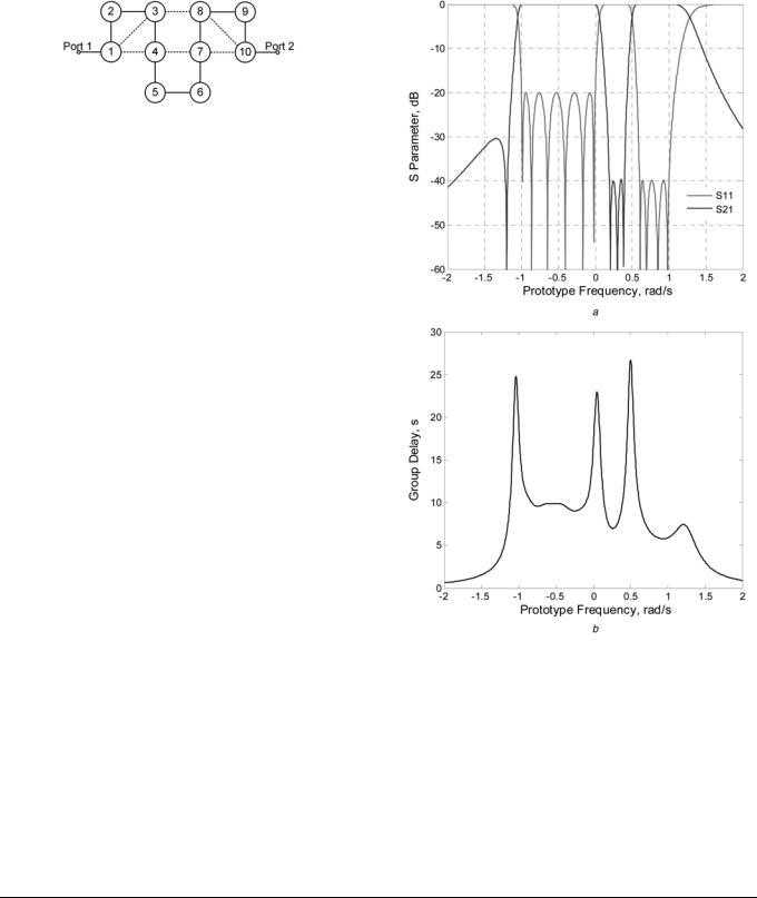
A tenth-order asymmetrical dual-band filter with different passband return loss levels (LR1 ¼ 20 dB, LR2 ¼ 40 dB) is illustrated as the first example. Three transmission zeros are placed at j0.205, j0.3, j0.385 on the imaginary axis to produce two asymmetrical passbands and the other pure imaginary transmission zero – j1.2 is used to provide a better rejection level on the lower side of the passband. A complex pair of transmission zeros are placed at +0.4 2 j0.5 to offer group delay equalisation for the left passband. Using the iterative technique described in Section 2.1, reflection zeros (sRzP) and filter poles (sPP) can be determined and then the filter polynomials are able to be constructed. The external quality factor qe1 is calculated to be 1.055 using (9). A topology that cannot be synthesised directly has been chosen here for demonstration and is shown in Fig. 1. Optimisation is performed to obtain the corresponding coupling matrix and the final result is listed in Table 1. Fig. 2 shows the responses (transmission/
IET Microw. Antennas Propag., 2012, Vol. 6, Iss. 1, pp. 24–30 doi: 10.1049/iet-map.2011.0261
www.ietdl.org
Fig. 1 Topology of Example-A
reflection loss and group delay) associated with the final coupling matrix. As shown in Fig. 2b, by introducing a pair of complex transmission zeros at +0.4 2 j0.5, the group delay variation of the left passband has been reduced.
2.4Example-B
By applying the same design approach, a 16th-order quadband filter with a symmetric response and a compact topology, as shown in Fig. 3, is demonstrated. The four symmetrically located passbands of the filter are +[j0.6, j1] and +[j0.15, j0.3]. The return loss level of the first and fourth passbands are designed to be 20 dB, and the return
loss of the second and third |
passbands |
are obtained |
as |
|
30 dB, after the |
polynomials |
iterations synthesis. Twelve |
||
pure imaginary |
transmission |
zeros are |
positioned |
at: |
+j0.035, +j0.075, +j0.405, +j0.45, +j0.495, +j1.5 to separate different passbands. After coupling matrix optimisation the resultant coupling coefficients (non-zero values) and calculated external quality factors are shown below. Their corresponding S parameter responses at normalised frequency are given in Fig. 4.
qe1 ¼ qe16 ¼ 1.5327, |
m12 ¼ 20.7406, |
m23 |
¼ 0.2817, |
|
m34 ¼ 20.1649, m45 ¼ 0.0189, m56 ¼ 20.3334, m67 |
¼ |
|||
0.3436, m78 ¼ 20.5646, |
m89 ¼ 0.2166, |
m9,10 |
¼ 0.6948, |
|
m10,11 ¼ 0.291, m11,12 ¼ 0.325, m12,13 ¼ 0.122, |
m13,14 |
¼ |
||
0.1277, m14,15 ¼ 0.2181, m15,16 ¼ 20.4768, m18 |
¼ 0.2021, |
|||
m27 ¼ 0.346, m36 ¼ 20.2469, m5,12 ¼ 0.2348, |
m6,11 |
¼ |
||
0.1366, m7,10 ¼ 0.43, m9,16 ¼ 20.6016, m10,15 ¼ 20.0515, m11,14 ¼ 20.3589.
The time needed for each design of the above two examples is less than 5 min on a personal computer with a processor with 2.66 GHz clock speed and 2 GB of RAM. The majority of the time has been spent by GA optimisation to find the proper initial value for the followed SQP local optimisation procedure. It is worth pointing out that, to demonstrate the advantages of the cost function [i.e. (3)] proposed in this work, the cost function in [6] has also been attempted to acquire the desired coupling matrices of Examples A and B using the hybrid optimisation algorithm. However, the optimisation failed to converge in a reasonable time for both examples. As mentioned in
Table 1 Coupling matrix of Example-A
Fig. 2 Computed responses of Example-A
a S parameter in dB
b Group delay responses
Section 2.2, the program may converge to the desired solutions by altering the weighting functions of each terms of the cost function in [6].
3 Experimental verifications
The coupling matrix of an eighth-order dual-band filter has been obtained using above optimisation method and
0.1357 |
20.6232 |
20.4024 |
20.5083 |
0 |
0 |
0 |
0 |
0 |
0 |
20.6232 |
20.0280 |
0.5753 |
0 |
0 |
0 |
0 |
0 |
0 |
0 |
20.4024 |
0.5753 |
0.1783 |
20.3619 |
0 |
0 |
0 |
0.5093 |
0 |
0 |
20.5083 |
0 |
20.3619 |
20.2984 |
0.4653 |
0 |
0.0599 |
0 |
0 |
0 |
0 |
0 |
0 |
0.4653 |
20.1053 |
20.0640 |
0 |
0 |
0 |
0 |
0 |
0 |
0 |
0 |
20.0640 |
20.0121 |
0.3198 |
0 |
0 |
0 |
0 |
0 |
0 |
0.0599 |
0 |
0.3198 |
20.3412 |
0.5129 |
0 |
0.8137 |
0 |
0 |
0.5093 |
0 |
0 |
0 |
0.5129 |
20.0287 |
20.4145 |
0.3821 |
0 |
0 |
0 |
0 |
0 |
0 |
0 |
20.4145 |
0.4141 |
0.0242 |
0 |
0 |
0 |
0 |
0 |
0 |
0.8137 |
0.3821 |
0.0242 |
0.1357 |
|
|
|
|
|
|
||||
IET Microw. Antennas Propag., 2012, Vol. 6, Iss. 1, pp. 24–30 |
|
|
|
|
27 |
||||
doi: 10.1049/iet-map.2011.0261 |
|
|
|
& The Institution of Engineering and Technology 2012 |
|||||

www.ietdl.org
Fig. 3 Topology of Example-B
calculated |
external quality |
factor are: qe1 ¼ qe8 ¼ 1.7278, |
m12 ¼ m78 |
¼ 0.6452, m23 ¼ m67 ¼ 0.0476, m34 ¼ m56 ¼ |
|
0.6623, |
m45 ¼ 0.3786, |
m14 ¼ m58 ¼ 20.5389. The |
normalised coupling matrix of the low-pass prototype is transformed to the real frequency domain, giving:
Qe1 ¼ Qe8 ¼ 13.2908, M12 ¼ M78 ¼ 0.0840, M23 ¼ M67 ¼ 0.0062, M34 ¼ M56 ¼ 0.0862, M45 ¼ 0.0493, M14 ¼ M58 ¼ 20.0702. Their corresponding prototype S parameter
responses are shown in Fig. 6. The approach in [23] has been followed to acquire physical dimensions of this dual-band filter from these external quality factor and coupling coefficients values.
It should be noted that the cross couplings M14 and M58 have a negative sign as opposite to other coupling coefficients. Normally in a rectangular waveguide these different signs are achieved by using different coupling irises (i.e. capacitive or inductive irises). In this paper, the coupling irises used are exclusively capacitive, which makes the required negative coupling more difficult to realise. As shown in Fig. 5b, the negative couplings M14, M58 are achieved by employing two TE102 mode cavities 1 and 8, whereas the remaining six cavities operate with TE101 mode. A similar principle has been used in [25] but in this case it is for all inductive coupling irises. The two
Fig. 4 Computed responses of Example-B
realised using waveguide technology to verify this design approach. This dual-band filter is designed to operate at a centre frequency of 10 GHz with two symmetrically located passbands of 9.35–9.70 and 10.30–10.65 GHz. The attenuation at the stopband is designed to be 45 dB and achieved by introducing two transmission zeros occur at 9.88 and 10.12 GHz. The return loss of both passbands is 20 dB. The topology of the filter is shown in Fig. 5a. After getting the characteristic polynomials of the low-pass prototype which fulfil the filter specifications, optimisation was performed to generate the coupling matrix. The nonzero values of the coupling matrix after optimisation and
Fig. 5 Eighth-order X-band dual-band filter
a Topology of the designed dual-band filter
b Photograph of one-half of the symmetrical dual-band waveguide filter with tuning screw holes, b ¼ 10.16 mm. The first and eighth cavities operate at TE102 mode while the rest resonators operate at conventional TE101 mode
28
& The Institution of Engineering and Technology 2012
Fig. 6 Symmetrical dual-band filter performance obtained from prototype coupling matrix (i.e. ideal responses), CST simulation and the measurement after tuning
a S11 in dB
b S21 in dB
IET Microw. Antennas Propag., 2012, Vol. 6, Iss. 1, pp. 24–30 doi: 10.1049/iet-map.2011.0261
desired features for this kind of structure are: firstly, it is easy for computer numerical control milling, since only two simple identical parts need to be fabricated and assembled. A good insertion loss can be achieved using the E-plane split configuration. Secondly, this all-capacitive-iris split-block structure is compatible with the multi-layer micromachining technology that has been developed for fabricating millimetre-wave components [26]. It is planned that the current design will be scaled to 300 GHz and fabricated using this layered micromachining technology.
There are drawbacks of this all-capacitive coupling structure. It is not suitable for filters containing small couplings. As the capacitive iris itself is a section of propagating waveguide, it causes a relatively strong coupling even with small gaps [27]. Additionally, compared with an inductive-iris filter, filters with capacitive irises have a higher rejection in the upper stopband, but a lower rejection in the frequency range close to the cut-off of the feeding waveguide [28]. Since the capacitive irises are in fact resonant irises with their resonance frequency centred at TE10 mode cut-off [29]. This results in the poorer-than- theory rejection at lower stopband, as shown in Fig. 6b. Additionally, standard X-band waveguide resonator filters often suffer from poor higher stopband behaviour owing to the appearance of higher order modes and the resonances at higher harmonic frequencies, which occur at frequencies of 1.6–1.7 times the centre frequency. For the X-band filter presented in this paper, situation becomes worse since an extra resonance at 12.46 GHz introduced by the first and eighth cavity operating at the unwanted TE103 mode was generated. This leads to the worse-than-theory attenuation performance at the upper stopband, as shown in Fig. 6b. The input/output of the filter is a WR-90 rectangular waveguide interface. The pieces were machined from copper. The measured response before tuning was slightly shifted to higher frequencies. It was identified that this shift was owing to the round corners (with a radius of 1.6 mm) of each resonator, which was not taken into account in the design. After adding tuning screws to the resonators and coupling irises, the frequency shift was corrected and the measurement result showed excellent agreement with the simulation as shown in Fig. 6.
4 Conclusions
This paper presents a coupling matrix design procedure based on a hybrid optimisation algorithm which can be applied to cross-coupled multi-band filters having specified, diverse topologies and responses. The characteristic polynomials fulfil the filter specifications are generated by an iterative design technique based on polynomial fit. This iterative synthesis method guaranteed convergence and is also able to generate polynomials for multi-band filter with different return loss levels at each passband. After calculating the characteristic polynomials, a hybrid optimisation technique is performed directly on the coupling matrix to seek the optimal set of coupling coefficients. This hybrid optimisation technique employs a GA to choose strong initial values for the following SQP search and was described in detail in [6]. At each optimisation iteration, a novel and efficient cost function that measures the difference of the frequency locations of reflection and transmission zeros is evaluated. This cost function eliminates the need of weighting functions or searching. An equation to calculate external quality factors from
IET Microw. Antennas Propag., 2012, Vol. 6, Iss. 1, pp. 24–30 doi: 10.1049/iet-map.2011.0261
www.ietdl.org
polynomials has been derived for filters with both symmetrical and asymmetrical responses and presented in this paper. Coupling matrices for a complex dual-band and quad-band filter with topologies which cannot be synthesised analytically have been demonstrated as two examples. An X-band dual-band waveguide filter has been designed, fabricated and measured to verify this design approach; and excellent agreement between the simulation result and measured result has been demonstrated. A novel technique to achieve both positive and negative couplings using the same kind of coupling irises has been employed by the dual-band waveguide filter and presented.
5 Acknowledgments
This work was supported in part by the UK Engineering and Physical Science Research Council (EPSRC), and by a fellowship from the Automatic RF Techniques Group. Many constructive suggestions by reviews of this paper are also greatly appreciated.
6References
1 Atia, W.A., Zaki, K.A., Atia, A.E.: ‘Synthesis of general topology multiple coupled resonator filters by optimisation’. IEEE MTTS Int. Microw. Symp., Baltimore, USA, June 1998, pp. 821–824
2Amari, S.: ‘Synthesis of cross-coupled resonator filters using an analytical gradient-based optimisation technique’, IEEE Trans. Microw. Theory Tech., 2000, 48, (9), pp. 1559–1564
3Mokhtaari, M., Borenemann, J., Rambabu, K., Amari, S.: ‘Coupling matrix design of dual and triple passband filters’, IEEE Trans. Microw. Theory Tech., 2006, 54, (11), pp. 3940–3946
4Amari, S., Rosenberg, U., Bornemann, J.: ‘Adaptive synthesis and design of resonator filters with souce/load-multiresonator coupling’,
IEEE Trans. Microw. Theory Tech., 2002, 50, (8), pp. 1969–1978
5 Jayyousi, A.B., Lancaster, M.J.: ‘a gradient-based optimisation technique employing determinants for the synthesis of microwave coupled filters’. IEEE MTTS Int. Microw. Symp., Fort Worth, USA, June 2004, pp. 1369–1372
6Nicholson, G.L., Lancaster, M.J.: ‘Coupling matrix synthesis of crosscoupled microwave filters using a hybrid optimisation algorithm’, IET Microw. Antennas Propag., 2009, 3, (6), pp. 950–958
7Bell, H.C.: ‘Canonical asymmetric coupled-resonator filter’, IEEE Trans. Microw. Theory, 1982, 30, (9), pp. 1335–1340
8Cameron, R.J.: ‘General coupling matrix synthesis methods for chebyshev filtering functions’, IEEE Trans. Microw. Theory Tech., 1999, 47, (4), pp. 433–442
9Cameron, R.J.: ‘Advanced coupling matrix synthesis techniques for microwave filters’, IEEE Trans. Microw. Theory, 2003, 51, (1), pp. 1–10
10Macchiarella, G.: ‘Accurate synthesis of in-line prototype filters using cascaded triplet and quadruplet sections’, IEEE Trans. Microw. Theory Tech., 2002, 50, (7), pp. 1779–1783
11Tamiazzo, S., Macchiarella, G.: ‘An analytical technique for the synthesis of cascaded N-tuplets cross-coupled resonator microwave filters using matrix rotations’, IEEE Trans. Microw. Theory Tech., 2005, 53, (5), pp. 1693–1698
12Lee, J., Uhm, M.S., Yorn, I.B.: ‘A dual-passband filter of canonical structure for satellite application’, IEEE Microw. Wirel. Comput. Lett., 2004, 14, (6), pp. 271–273
13Lenoir, P., Bila, S., Seyfert, F., et al.: ‘Synthesis and design of asymmetrical dual-band bandpass filters based on equivalent network simplification’, IEEE Trans. Microw. Theory Tech., 2006, 54, (7), pp. 3090–3097
14Macchiarella, G., Tamiazzo, S.: ‘A design technique for symmetric dualband filters’. IEEE MTTS Int. Microw. Symp., 2005, pp. 115–118
15Macchiarella, G., Tamiazzo, S.: ‘Design technique for dual-passband
filters’, IEEE Trans. Microw. Theory Tech., 2005, 53, (11), pp. 3265–3271
16Lee, J., Sarabandi, K.: ‘A synthesis method for dual-passband microwave filters’, IEEE Trans. Microw. Theory Tech., 2007, 55, (6), pp. 1163–1170
17Lee, J., Sarabandi, K.: ‘Design of triple-passband microwave filters using frequency transformations’, IEEE Trans. Microw. Theory Tech., 2008, 56, (1), pp. 187–193
29 & The Institution of Engineering and Technology 2012
www.ietdl.org
18 |
Lamecki, A., Kozakowski, P., Mrozowski, M.: ‘Fast synthesis of |
24 |
Atia, A.E., Williams, A.E.: ‘Narrow-bandpass waveguide filters’, IEEE |
|
coupled-resonator filters’, IEEE Microw. Wirel. Compon. Lett., 2004, |
|
Trans. Microw. Theory Tech., 1972, 20, (4), pp. 258–265 |
|
14, (4), pp. 174–176 |
25 |
Rosenberg, U.: ‘New ‘Planar’ waveguide cavity elliptic function filters’. |
19 |
Kozakowski, P., Mrozowski, M.: ‘Automated synthesis of coupled |
|
Proc 25th European Microwave Conf., 1995, pp. 524–527 |
|
resonator filters with a given topology’. 14th Int. Conf. Microwave |
26 |
Wang, Y., Ke, M., Lancaster, M.J.: ‘Micromachined 38 GHz cavity |
|
Radar Wireless Communications, Gdansk, Poland, May 2002, |
|
resonator and filter with rectangular-coaxial feed-lines’, IET Microw. |
|
pp. 373–376 |
|
Antennas Propag., 2009, 3, (1), pp. 125–129 |
20 |
Dominic, D., Francois, B.: ‘An iterative design procedure for the |
27 |
Ruiz-Cruz, J.A., Zaki, K.A., Montejo-Garai, J.R., Rebollar, J.M.: |
|
synthesis of generalized dual-bandpass filters’, Int. J. RF Microw. |
|
‘Rectangular waveguide elliptic filters with capacitive and inductive |
|
Comput. Aided Eng., 2009, 19, (5), pp. 607–614 |
|
irises and integrated coaxial excitation’. IEEE MTTS Int. Microw. |
21 |
McGee, W.: ‘Numerical approximation technique for filter characteristic |
|
Symp. Digest, June 2005, pp. 269–272 |
|
functions’, IEEE Trans. Microw. Theory Tech., 1967, 14, (1), pp. 92–94 |
28 |
Rosenberg, U., Amari, S., Bornemann, J.: ‘Inline TM110-mode filters |
22 |
Dominic, D., Francois, B.: ‘Iterative design techniques for all-pole dual- |
|
with high-design flexibility by utilizing bypass couplings of |
|
bandpass filters’, IEEE Microw. Wirel. Compon. Lett., 2007, 17, (11), |
|
nonresonating TE10/01 modes’, IEEE Trans. Microw. Theory Tech., |
|
pp. 775–777 |
|
2003, 51, (6), pp. 1735–1742 |
23 |
Hong, J.-S., Lancaster, M.J.: ‘Microstrip filters for RF/microwave |
29 |
Craven, G.F., Skedd, R.F.: ‘Evanescent mode microwave components’ |
|
applications’ (Wiley-Interscience, 2001) |
|
(Artech House Inc., 1987) |
30 |
IET Microw. Antennas Propag., 2012, Vol. 6, Iss. 1, pp. 24–30 |
& The Institution of Engineering and Technology 2012 |
doi: 10.1049/iet-map.2011.0261 |