

DOI 10.1007/s11141-016-9698-2
Radiophysics and Quantum Electronics, Vol. 59, No. 4, September, 2016
(Russian Original Vol. 59, No. 4, April, 2016)
SMALL-SIZE WAVEGUIDE DIPLEXER BASED ON E-PLANE QUASI-PLANAR FILTERS
M. B. Manuilov and K. V. Kobrin |
UDC 621.396.67 |
We propose a new small-size version of a waveguide diplexer based on quasi-planar filters with E-plane ridge sections and inductive diaphragms on a single metal inset made of a thin foil. The diplexer contains an E-plane waveguide bifurcation and a matching stepwise transition. The e ective hybrid method, which is based on the Galerkin method allowing for the field singularity at the edges, the mode matching method, and the generalized scattering matrix method, has been developed for electrodynamic analysis of the given class of diplexers. We present characteristics of the optimized version of the design of a centimeter-wave diplexer, whose length is approximately 1.5 times shorter compared with known counerparts.
1.INTRODUCTION
Waveguide diplexers and quasi-planar filters are used widely in the process of development of different communication systems operated in the centimeter and millimeter wavelength bands, including such wireless communication systems as “Local Multipoint Distribution Services” (LMDS), “Multichannel Video Distribution Systems” (MVDS), etc. Diplexers are designed to ensure frequency separation of the reception and transmission lines in the transceivers of communication hardware. Specifically, they are used to support frequency separation of standard communication bands into subbands.
Some known design versions of diplexers use filters based on metal-foil insets in the E-plane of a rectangular waveguide [1–5]. The parameters of a quasiplanar filter are determined mainly by the topology of the metal inset, which forms a system of inhomogeneities. The use of the photolithography technology to produce such insets allows one to fulfill dimensional requirements with an accuracy of 10 μm and less, thus ensuring manufacturing precision, high repeatability of the parameters, and comparatively low prices of the design. Such high-technology designs also ensure a low level of inserted losses and are used successful in the centimeter and millimeter wavelength bands corresponding to the frequencies 10–150 GHz.
The design of bandpass filters based on the E-plane longitudinal inductive diaphragms [1, 2] has a spurious pass band, which is located relatively close to the main pass band. This can lead to the case where the width of the stop band and the level of attenuation in it turn to be insu cient for some practical applications, i.e., for diplexers and multiplexers. To increase the sharpness of the slopes of frequency characteristics of such filters, one can use more resonators, but this is accompanied by an increase in the ohmic loss and a greater size of the entire structure.
To solve this problem, we proposed several design versions, including quasiplanar filters based on ridge sections and inductive strips [4–7]. Filters of this type ensure better gain slopes and symmetry of the frequency characteristic. Moreover, such filters allow one to expand significantly the upper rejection band and are characterized by low inserted losses and a smaller size. In this connection, in what follows we
m manuilov@sfedu.ru
Southern Federal University, Rostov-on-Don, Russia. Translated from Izvestiya Vysshikh Uchebnykh Zavedenii, Radiofizika, Vol. 59, No. 4, pp. 333–342, April 2016. Original article submitted March 10, 2015; accepted September 16, 2015.
c |
301 |
0033-8443/16/5904-0301 2016 Springer Science+Business Media New York |

Fig. 1. Waveguide diplexer based on quasiplanar filters with ridges and inductive strips in the E-plane: the three-dimensional model (a) and the cross section in the E-plane (b). (1) is the input, and (2) and (3) are the outputs.
propose and study a new design of the diplexer with band-limited filters based on E-plane ridge sections and inductive strips.
2.DESIGN OF THE DIPLEXER
The proposed diplexer (Fig. 1) is based on the E-plane waveguide junction, since this design version has better band properties compared with, e.g., the version based on H-plane junctions [1]. The diplexer design includes a stepwise matching transition with an arbitrary number of sections. Band-limited filters of the diplexer are based on the evanescent waveguide. In this case, the height b of all waveguides is identical, and evanescence of the sections with filters (the sections having the length Lf in Fig. 1b) is achieved by decreasing the width of the waveguides.
The body of the diplexer is divided into two halves in the E-plane. Between the halves, an inset with ridges and longitudinal diaphragms, which is made of a thin metal foil, is installed (Fig. 1b). The resonators of the filters are formed by ridge sections (of the H type) separated by sections of evanescent waveguides. Between the ridge sections, inductive strips (longitudinal diaphragms) are located along the entire height of the waveguide. This design version is technologically e cient, since it allows one to manufacture both filters of one foil sheet, which ensures manufacture precision. Inductive strips make it possible to reduce the length of evanescent coupled regions and the length of the entire structure. An increased height of evanescent waveguides allows one to increase gaps between ridges and make the losses somewhat lower.
302
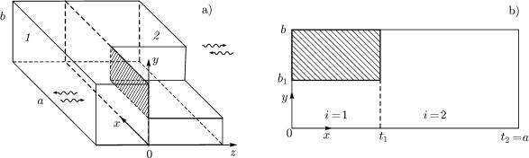
Fig. 2. The joint of rectangular and ridge waveguides (a) and the transverse section of a ridge waveguide (b). 1 and 2 in panel a are regular regions.
3.METHOD OF ANALYSIS
When stating the problem of electrodynamic analysis of the diplexer, it was assumed that the structure in Fig. 1 can contain an arbitrary number of matching stepwise inhomogeneities and ridge sections of the filter. To solve this problem, we propose an e ective hybrid electrodynamic method for analysis of this class of structures, which is based on the Galerkin method allowing for the field singularity at the edges, the method of mode matching, and the method of generalized scattering matrices.
Solving of the problem includes the following stages: 1) decomposition of the complex initial structure into basic units (inhomogeneities); 2) solving of the eigenvalue problem for a ridge waveguide (calculation of eigenfrequencies and normal-wave fields); and 3) solution of problems of scattering by basic inhomogeneities and calculation of their multimode scattering matrices; 4) recomposition of multimode S-matrices of the inhomogeneities and calculation of scattering matrices of the filter and the waveguide junction with a matching transition; and 5) calculation of the multimode scattering matrix of the diplexer.
As a result of decomposition of the structure under consideration, the joint of a rectangular waveguide and a ridge waveguide (Fig. 2a), the joint of rectangular waveguides, and a waveguide T-junction were singled out as basic units. The H- and E-modes were used as the wave basis for solution of the corresponding basic scattering problem.
Due to this, we first solved the problem of calculation of the critical frequencies and fields of the ridge waveguide [4]. Its transverse cross section is shown in Fig. 2b. The boundary condition corresponding to the electric or magnetic wall can be imposed in the planes x = 0 or y = 0. The eigenvalue problems are solved independently for the H and E modes and are reduced to the homogeneous integral Friedholm equation of the first kind with respect to the tangential components of the electric field at the boundary of regular regions x = t1 (Fig. 2b) [4].
In the case of the H-modes, we arrive at an integral equation with respect to the tangential component of the electric field at the boundary of regular regions: Ey(x = t1) f m(y). Solution of this equation is found by using the Galerkin method with the basis in the form of weighted Gegenbauer polynoms, whose weighting factor allows for the field asymptotics at the inhomogeneity edge:
N |
|
f m(y) = ui 1 − (y/b1)2 τ −1/2 C2τi+gy (y/b1), |
(1) |
i=0
where ui are unknown coe cients, Cτi (x) is the Gegenbauer polynomial, the asymptotics factor for the rectangular edge is τ = 1/6, and
0, for the electric wall in the plane y = 0;
gy = |
(2) |
1, |
for the magnetic wall in the plane y = 0. |
303

In the case of the E-modes, the integral equation is written for the component Ez(x = t1) f e(y), and the solution is sought for in the form of the expansion
|
|
|
N |
2 τ +1/2 |
|
|
|
f |
e |
|
ui 1 − (y/b1) |
τ +1 |
(y/b1). |
|
|
|
(y) = |
|
C2i+1−gy |
(3) |
i=0
Solving the integral equation by the Galerkin method yields a homogeneous system of linear algebraic equations (SLAE). By making the SLAE determinant equal to zero, we obtain the transcendental equation for calculation of the spectrum of the critical waveguide frequencies. The fast convergence and high accuracy of this solution ensure high e ciency of the entire proposed hybrid method of diplexer calculation to a great extent.
At the following step, we calculate multimode scattering matrices of basic inhomogeneities. The mode matching method fits well for coordinate problems of this type [4]. Specifically, when analyzing the connection of the rectangular and ridge waveguides (Fig. 2a), the fields in regular regions 1 and 2 are represented as a superposition of the incident and reflected H- and E-modes of the rectangular and ridge waveguides, respectively. The eigenfunctions of the ridge waveguide are written in accordance with the transverse-resonance method [8] and contain critical wave numbers and field expansion coe cients found from the solution of the eigenvalue problem for the ridge waveguide.
We write the vector potentials AE = (0, 0, AE ), AH = (0, 0, AH ) in the regular regions ν = 1, 2 in Fig. 2a in the form of expansions with respect to the incident and scattered modes:
|
|
∞ |
|
|
|
|
|
|
|
|
|
|
|
|
AH(ν) |
= |
|
ZH(νq) |
|
TH(νq) exp(−jγH(νq)z) + RH(νq) exp(jγH(νq)z) |
ψH(νq)(x, y), |
(4) |
|||||||
|
|
q=1 |
|
|
|
|
|
|
|
|
|
|
|
|
|
|
∞ |
|
|
|
|
|
|
|
|
|
|
|
|
AE(ν) |
= |
|
YE(νp) |
|
TE(νp) exp(−jγE(νp)z) − RE(νp) exp(jγE(νp)z) |
ψE(νp)(x, y), |
(5) |
|||||||
|
|
p=1 |
|
|
|
|
|
|
|
|
|
|
|
|
where |
|
|
|
|
ωμ0 |
|
1 |
|
ωε0 |
|
1 |
|
|
|
|
|
ZH(νq) = |
= |
, YE(νp) = |
= |
, |
|
|
||||||
|
|
(ν) |
(ν) |
(ν) |
(ν) |
|
|
|||||||
|
|
|
|
|
γHq |
YHq |
|
γEp |
ZEp |
|
|
|||
ω is the angular frequency of the radiation, ε0 and μ0 are the electric and magnetic constants, respectively, the complex amplitudes of the incident and scattered waves are denoted as TH(νq), RH(νq), TE(νp), RE(νp), and the eigenfunctions of the rectangular waveguide have the form
ψ(1) |
(x, y) |
= ψ(1) (x, y) |
= |
|
Q(1) |
2 − δ0αm |
cos(α |
|
x |
− |
g π/2) |
2 − δ0βn |
cos(β y |
− |
g π/2), (6) |
||||||||||||||||
Hq |
|
Hmn |
|
|
Hq |
a |
|
|
|
|
m |
|
x |
|
|
|
|
|
|
|
b |
n |
|
y |
|||||||
|
|
|
|
|
|
|
|
|
|
|
|
|
|
|
|
|
|
|
|
|
|||||||||||
|
|
ψ(1) |
(x, y) = ψ(1) |
(x, y) = Q(1) |
2 |
sin(αmx + gxπ/2) |
|
|
2 |
sin(βny + gyπ/2), |
|
|
(7) |
||||||||||||||||||
|
|
|
|
|
|
||||||||||||||||||||||||||
|
|
Ep |
|
Emn |
|
|
Ep |
a |
|
|
|
|
|
|
b |
|
|
|
|
|
|
|
|
|
|
||||||
|
|
|
|
|
|
|
|
|
|
|
|
|
|
|
|
|
|
|
|
|
|
|
|
|
|||||||
|
(1) |
(1) |
|
|
|
2 |
|
|
|
|
|
|
|
|
|
|
gx |
|
π |
|
gy |
|
π |
||||||||
|
γHq |
= γEp |
= γmn(1) , |
γmn(1) |
= k2 − αm2 |
− βn2, |
αm = |
m + |
|
|
|
|
|
, βn = |
n + |
|
|
|
|
. |
|||||||||||
|
2 |
|
|
a |
2 |
|
b |
||||||||||||||||||||||||
Allowing for the notations in Fig. 2, the eigenfunctions of the ridge waveguide in relationships (4) and (5) are written, in accordance with the transverse-resonance method [8] as
|
2 |
N |
|
|
2 − δ0 βin |
|
|
|
|
|
|
|
ψ(2) |
(x, y) = Q(2) |
φ(i) |
(x) |
|
cos(β |
|
y |
− |
g π/2), |
(8) |
||
Hq |
Hq |
Hqn |
|
|
bi |
in |
|
y |
|
|||
|
i=1 n=0 |
|
|
|
|
|
|
|
|
|
|
|
304

Fig. 3. Recomposition scheme of the waveguide diplexer.
2 |
N |
|
|
|
|
|
|
2 |
|
|
|
||
ψE(2)p (x, y) = QE(2)p |
φE(i)pn (x) |
|
sin(βiny + gyπ/2), |
(9) |
||
|
|
|||||
i=1 n=1−gy |
|
bi |
|
|||
|
|
|
|
|
||
φ(Hi)qn (x) =
φ(Ei)pn (x) =
1, α = β;
δα β =
0, α = β,
A(1)Hqn cos(σH(1)qn x − gxπ/2), A(2)Hqn cos[σH(2)qn (a − x)],
A(1)Epn sin(σE(1)pn x + gxπ/2), A(2)Epn sin[σE(2)pn (a − x)],
i = 1, x [0, t1]; i = 2, x [t1, a],
i = 1, x [0, t1]; i = 2, x [t1, a],
0, for the electric wall in the plane x = 0;
gx =
1, for the magnetic wall in the plane x = 0,
(i) |
|
|
(i) |
|
|
|
|
gy π |
|
||
(σHqn )2 = (αHq )2 − (βin)2, (σEpn )2 = (αEp )2 − (βin)2, βin = n + |
|
|
|
, |
|||||||
2 bi |
|||||||||||
(2) |
2 |
2 |
2 |
(2) |
2 |
2 |
2 |
|
|
|
|
(γHp ) = k |
|
− (αHp ) , (γEp ) = k |
|
− (αEp ) , |
|
|
|
|
|||
where k is the wave number, αHq , αEp and A(Hi)qn , A(Ei)pn are calculated by solving the eigenvalue problem for
the ridge waveguide, gy is determined in Eq. (2), and Q(Hνq) and Q(Eνp) in Eqs. (6)–(9) are the normalization coe cients. From the condition of continuity of the tangential components of the electric and magnetic fields at the joint of regular waveguides, one obtains a system of equations with respect to unknown amplitudes of the incident and reflected waves. By using standard transformations, we obtain a multimode scattering matrix of the inhomogeneity in analytical form [4].
Di raction problems for joints of rectangular waveguides with di erent cross sections, as well as for waveguide T-junctions, are solved in a similar way.
When realizing the recomposition procedures, one first finds multimode scattering matrices of the filters and the matching transition with the waveguide T-junction. For this purpose, an e cient algorithm of recomposition of cascade connection of two serially connected inhomogeneities is used, which allows for the symmetry of assembled scattering matrices [4]. Assembling of inhomogeneity scattering matrices in series yields multimode S-matrices of the filters, as well as the S-matrix of the matching transition with the waveguide T-junction.
The recomposition procedure for the waveguide diplexer is performed by analogy with work [3]. The recomposition scheme (Fig. 3) includes the scattering matrix of a waveguide T-junction with the matching transition SB, the matrices of regular waveguide sections SWi and matrices of channel filters SFi (i = 1, 2). The column vectors of the complex amplitudes of the incident (+) and reflected (−) waves will be denoted A±k , B±k , and C±k , where the subscript k = 1, 2, 3 corresponds to the number of the diplexer input. The
305