

диафрагмированные волноводные фильтры / bc07a129-fda0-4718-835e-451c34d64333
.pdfWe1A-5
A Synthesis-Based Design Procedure for Waveguide Duplexers Using a Stepped E-Plane Bifurcated Junction
Giuseppe Macchiarella#1, Gian Guido Gentili #, Luciano Accatino*, Vittorio Tornielli di Crestvolant%
#Politecnico Di Milano, Italy
*ACConsulting, Italy
%European Space Agency (ESA-ESTEC), The Netherlands 1giuseppe.macchiarella@polimi.it
Abstract— A novel design procedure for waveguide duplexers using stepped E-plane bifurcated junctions is presented. First, a simple model of this junction is devised, suited for the synthesis of star-junction diplexers (a novel procedure has been developed). The characteristic polynomials of the channel filters obtained by this procedure are then employed for the synthesis of the channel filters. To allow transmission zeros in the response, an in-line topology with frequency-dependent (resonant) couplings is adopted. The filters are synthesized with a recently proposed technique (here adapted for waveguide implementation). Furthermore, a new type of resonating coupling structure is adopted (the stopband singlet), allowing the positioning of the transmission zeros very close to the passband. The novel design technique is demonstrated with a Ka-band duplexer for satellite applications.
Keywords—duplexers, E-plane bifurcation, frequencydependent couplings, singlet
I. INTRODUCTION
Satellite communications are requiring more and more demanding filtering structures in last generation equipment [1]. For output combiners, very stringent requirements concern today selectivity, overall size & weight, power handling, losses. The increase of selectivity (without penalizing the size) calls for the introduction of transmission zeros in the filter response; moreover, suitable solutions for the combiner structure must be devised to optimize weight and size (footprint). Here we reelaborate an old solution, widely used (with all-pole filters) many years ago. We are referring to duplexers in rectangular waveguide, with an E-plane, stepped bifurcated junction [2-5]. This solution optimizes the diplexer footprint and simplify the device fabrication (in-line filters topology). To allow for transmission zeros in the response we have introduced resonating couplings in the filters, implemented through a novel structure, the stopband singlet. Another innovative contribution of this work is the development of a design approach for this class of diplexers (the design, in the past, was completely based on optimization). After introducing a simple equivalent circuit for the stepped bifurcated junction, a synthesis method has been developed for the whole duplexer, starting from a procedure found in the literature for shunt connected star-junction duplexers [6]. With the characteristic polynomials of the filters available, the synthesis of low-pass prototypes with frequencydependent couplings is carried out as described in [7]. The lowpass prototypes are then de-normalized in the passband domain
and suitably transformed, obtaining an equivalent circuit of the channel filters suited for the inclusion in the duplexer (waveguide resonators coupled by inductive irises or stopband singlets). The accuracy of the novel design approach is in many cases sufficient for the diplexer implementation (e.g. if tuning screws are used). Otherwise, accuracy can be improved by mean of full wave optimization, very fast in this case because of to the good starting point represented by the initial synthesis. We have validated the novel procedure with the design of a duplexer in Ka-band.
II. SYNTHESIS OF STEPPED BIFURCATED DUPLEXERS
The E-plane stepped bifurcated junction (Fig. 1) is typically used in power dividers [8]. Here we use this junction for allowing the stacking of the two filters on the broad wall. With this junction, we can also increase the height the filters cavities (b’) with respect the height of the input waveguide (b), for increasing the unloaded Q of the cavities.
Fig. 1. E-plane stepped bifurcated waveguide. a) Physical structure. b) Equivalent circuit (K represents an impedance inverter)
The dimensioning goal for this junction is to get S11 (common port) as small as possible (for the assigned steps number and length). This is easily achieved today exploiting full wave optimization (we used a home-developed mode-matching code). From a circuit viewpoint, the junction can be represented with the equivalent circuit in Fig. 1b; assuming the input port perfectly matched (S11=0), the parameter K of the inverters must be equal to1 2 . We observe that this ideal junction can be used in star-junction duplexers, determining the parallel connection of the filters input ports (the input series connection is “seen” by the filters as a parallel connection due to the inverters). We have then developed a synthesis procedure for
978-1-7281-6815-9/20/$31.00 © 2020 IEEE |
452 |
2020 IEEE/MTT-S International Microwave Symposium |
Authorized licensed use limited to: UNIVERSITY OF BATH. Downloaded on November 02,2020 at 04:01:46 UTC from IEEE Xplore. Restrictions apply.
computing the characteristic polynomials both of the whole duplexer and of the channel filters, for duplexers adopting this junction. Note that once the polynomials of the channel filters are available, the design of the duplexer reduces to the design of two separate filters, using well-known techniques [9].
To illustrate the effectiveness of the synthesis procedure, we have synthesized a duplexer with the following requirements:
Channel 1: f0=19.82 GHz, B=240 MHz, RL=23 dB, np=6, nz=2 (fz1=19.6767 GHz, fz2=19.968 GHz)
Channel 2: f0=20.082 GHz, B=240 MHz, RL=23 dB, np=6, nz=2 (fz1=19.9363 GHz, fz2=20.22775)
The duplexer response evaluated from the characteristic polynomials resulting from the synthesis procedure is shown in Fig. 2. If we replace the ideal model of the junction (Fig. 1b) with the scattering parameters evaluated by the real structure (Fig. 1a) the response of the duplexer is modified, remaining however not too far from the one obtained with the ideal junction (Fig. 2). Few optimization cycles of polynomials coefficients are sufficient to get the duplexer response practically coinciding with the ideal one (the optimized response is also shown in Fig. 2).
0 |
|
|
|
|
-10 |
|
|
|
|
S21 |
S11 |
S11 |
|
S31 |
-20 |
|
|
|
|
-30 |
|
|
|
|
-40 |
|
|
|
|
-50 |
|
|
|
|
19.6 |
19.8 |
20 |
20.2 |
20.3 |
Frequency (GHz)
Fig. 2. Computed response of the synthesized duplexer. Solid lines: ideal junction (fig. 1b). Dotted-dashed lines: real junction (S parameters from Fig. 1a), synthesized filters polynomials. Dotted lines: real junction with optimized filters polynomials
transformation, the frequency dependence of the two inverters becomes the same of the resonators. These inverters can be replaced with a T of series resonators, whose series arms interact with the main resonators (changing both the resonant frequency and the slope parameter). After suitable manipulations, the final de-normalized circuit can be represented as in Fig. 3b, where transmission line resonators (cavities) have replaced the cascaded series resonators of the synthesized (de-normalized) prototype. The cavities are assumed to operate on the TE102 mode to increase their unloaded Q. Note that the resonant couplings in the final equivalent circuit contribute to the slope parameter of the adjacent cavities (this in taken into account in the transformation of the de-normalized prototype). More details on the derivation of the circuit in Fig. 3b will be reported in an expanded version of this work.
|
1 |
M11 |
|
1 |
M22 |
1 |
M33 |
|
M22 |
1 |
M33 |
|
1 |
M22 |
|
Μ |
01 |
|
Μ |
12 |
|
Μ23+ |
Μ |
34 |
Μ45+ |
|
Μ |
56 |
|
Μ |
67 |
|
|
|
|
L23Ω |
|
L45Ω |
|
|
|
|
a)


 Cavity 1


 Cavity 2


 Cavity 3


 Cavity 4


 Cavity 5


 Cavity 6

|
jK0,1 |
|
|
jK1,2 |
|
|
|
fz23, |
|
|
|
|
fz45, |
|
|
jK5,6 |
|
|
jK6,7 |
|
|
|
|
|
|
|
jKc3,4 |
|
|
Kv45 |
|
|
|
|
|||||
|
|
|
|
|
|
Kv23 |
|
|
|
|
|
|
|
||||||
|
|
|
|
|
|
|
|
|
|
|
|
|
|
|
|
|
|
|
|
|
|
iris |
|
|
|
|
|
|
|
Rejection |
iris |
iris |
|||||||
iris |
|
Rejection |
iris |
||||||||||||||||
|
|
|
|
|
resonator |
|
|
resonator |
|
|
|
|
|
|
|||||
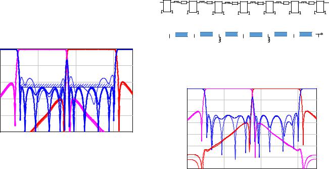
b)
Fig. 3. a) Synthesized low-pass prototype with frequency-dependent couplings (from [7]). b) De-normalized final equivalent circuit of the channel filters (after suitable manipulations of the de-normalized low-pass prototype).
0 |
|
|
|
|
-10 |
|
|
|
|
-20 |
S21 |
|
|
S31 |
S11 |
|
S11 |
|
|
|
|
|
||
-30 |
|
|
|
|
dB |
|
|
|
|
-40 |
|
|
|
|
-50 |
|
|
|
|
-60 |
|
|
|
|
-70 |
|
|
|
|
19.6 |
19.8 |
20 |
20.2 |
20.3 |
III. DESIGN OF THE WAVEGUIDE CHANNEL FILTERS
To make the channel filters as compact as possible we decided to use an in-line topology with frequency-dependent (resonant) couplings to introduce the required transmission zeros. Recently, synthesis solutions for this type of filters have appeared in the literature, overcoming the limitation of the previous design approaches, mainly resorting to optimization. More specifically, starting with the evaluated characteristic polynomials obtained by the duplexer synthesis, the procedure presented in [7] has been used to synthesize a low-pass prototype with two impedance inverters linearly varying with frequency (with K vanishing at the frequencies of the transmission zeros). Fig. 3a shows the resulting topology of the two synthesized filters (note that the frequency-dependent couplings are assigned to inverters 2-3 and 4-5). The prototypes are then de-normalized by means the usual low-pass to band-
pass transformation (Ω=(f/f0-f0/f)/Bn). Note that after this
453
Frequency (GHz)
Fig. 4. Simulated response of the overall duplexer (solid lines). The response with optimized filters polynomials is also reported for comparison (dotted lines)
Once the two channel filters have been de-normalized, the overall duplexer can be simulated by connecting the input ports of the filters to the bifurcated junction (represented by the computed S parameters). The result of the circuit simulation (Fig. 4) is very close to the equi-ripple response obtained with the optimized polynomial model of the filters (Fig. 2). This confirms the accuracy of the procedure developed for deriving the final configuration of the channel filters.
IV. DUPLEXER DIMENSIONING
The last step of the duplexer design consists in the implementation of the coupling elements in the filters (Fig. 3b). The frequency-independent reactances (jKi,i+1) are realized, as usual, with inductive irises, while the shunt rejection resonators
Authorized licensed use limited to: UNIVERSITY OF BATH. Downloaded on November 02,2020 at 04:01:46 UTC from IEEE Xplore. Restrictions apply.

requires a solution allowing a relatively large slope parameter (being the transmission zeros rather close to the passband). To this purpose, a new type of singlet is here proposed, namely the stopband singlet [10]. This structure adopts a cavity resonating on the TE301 mode, with the exciting TE10 mode acting as crosscoupling (fig. 5).
Fig. 5. a) Physical configuration of the stopband singlet (top view). b) Derivation of the equivalent circuit suitable for the implementation as resonant coupling
With a suitable dimensioning, the stopband singlet introduces one transmission zero with no reflection zero (this latter instead appears in classical passband singlets which adopt the TE201 as resonant mode). Consequently, its equivalent circuit (fig. 4b) is just the same of the rejection resonators in Fig. 3b (the length of the cavities connected to the singlets must be suitably modified to account for the additional electrical
length ΔΦ due to the singlets). A suitable dimensioning procedure has been developed for the stopband singlet allowing the assignment of the rejection resonators equivalent parameters (fz, Xeq) computed from the synthesis (fig.3b).
0 |
|
|
|
|
|
|
-10 |
|
|
|
|
|
|
-20 |
S21 |
|
S11 |
|
S11 |
S31 |
|
|
|
|
|||
dB-30 |
|
|
|
|
||
|
|
|
|
|
|
|
-40 |
|
|
|
|
|
|
-50 |
|
|
|
|
|
|
-60 |
|
|
|
|
|
|
-70 |
19.6 |
19.8 |
GHz |
20 |
20.2 |
20.4 |
|
||||||
|
|
Frequency (GHz) |
|
|||
Fig. 7. Simulated response (mode-matching) of the duplexer in Fig. 6
V. EXPERIMENTAL VALIDATION
As a preliminary validation of the novel filter configuration here introduced (resonant couplings with stopband singlet), one of the channel filters has been designed separately from the duplexer and fabricated (tuningless implementation). Fig. 8 shows the measured response (in the inset a photo of the fabricated device is also reported)
Fig. 6. Drawing of the duplexer (clamshell implementation)
The overall duplexer structure is represented in Fig. 6. Note that WR51 input/output waveguides are used, while the filters cavity have 12.95mm x 8.5mm cross section. Moreover, the symmetry along the vertical axis (E-plane) allows the clamshell implementation (easier fabrication and optimized overall size). The response of the duplexer in Fig. 6 has been evaluated with full-wave simulations (mode-matching). Fig. 7 shows the results obtained (optimization has been used to improve the final result).
454
Fig. 8. Measured (thick lines) and simulated (thin lines) response of a channel filter.
We note from the figure the very good agreement of the measured S21 with the simulations (mode matching). Considering the tuningless implementation, this result validates the novel design approach here proposed. The discrepancy observed between the measured and simulated S11 is due to a fabrication bug affecting the position of the last (asymmetrical) iris. After correcting this bug, we expect also the return loss in good agreement with the simulations.
VI. CONCLUSIONS
In this work, we have proposed an innovative approach to the design of waveguide duplexers with stepped E-plane bifurcated junction. The innovations introduced concern:
Authorized licensed use limited to: UNIVERSITY OF BATH. Downloaded on November 02,2020 at 04:01:46 UTC from IEEE Xplore. Restrictions apply.
1)The synthesis of the duplexer with a simplified model of the junction. The results are constituted by the characteristic polynomials of the channel filters
2)The synthesis of the channel filters implemented with frequency-dependent (resonant) couplings. Starting by the synthesized in-line low-pass prototype (generated with a procedure recently introduced in the literature), we have developed and original procedure to transform the prototype into a passband equivalent circuit with waveguide transmission lines (cavities) and shuntconnected coupling reactances (series resonating in case of transmission zero extraction).
3)A novel type of structure implementing the resonating coupling reactance, namely the stopband singlet. This singlet type presents only one transmission zero (no reflection zeros), making more accurate the physical implementation of the shunt-connected series resonators
in the filters equivalent circuit.
The final synthesized duplexer consists in the equivalent circuit of the channel filters connected to the ideal bifurcated junction. We have shown that after replacing the model of the junction with the simulated (full-wave) S parameters of the physical structure the response of the duplexer is only slightly degraded (a fast optimization allows to retrieve an almost equiripple response). The physical dimensioning of the duplexer is finally carried out by implementing the coupling reactances with inductive irises (constant couplings) or stopband singlets (resonating couplings).
We have validated the design procedure of the channel filters through the fabrication of a test prototype.
REFERENCES
[1]F. D. Paolis and C. Ernst, "Challenges in the Design of Next Generation Ka-Band OMUX for Space Applications”, 31st AIAA International Communications Satellite Systems Conference, October 2013, Florence,Italy
[2]R. Vahldieck , B. Varailhon de la Filolie "Computer aided design of parallel-connected millimeter-wave diplexers/multiplexers”, IEEE MTT-S Int. Microwave Symp. Dig., 1988, pp 435-438
[3]J. Dittloff, F. Arndt, “Rigorous Field Theory Design of Millimeter-Wave E-Plane Integrated Circuit Multiplexers” IEEE Trans. Microw. Theory Techn., vol. 37, n. 2, pp. 340-350, Febr. 1989
[4]J. Borneman, J. Uher, K.N. Patel, “Efficient full-wave CAD of waveguide diplexers”, 1996 Symp. Antenna Techn. Applied Electromagn.
Montreal (Canada), Aug. 1996
[5]L. Accatino, "Computer-Aided Design of a Ku-Band Antenna Diplexer", in Proc. of the 23th EMC, Madrid (Spain), Sept.1993, pp. 544-546.
[6]G. Macchiarella, S. Tamiazzo “Novel Approach to the Synthesis of Microwave Duplexers” IEEE Trans. Microw. Theory Techn., vol. 54, n.12, pp. 4281-4290, Dec. 2006
[7]Y. He, G. Macchiarella, Z. Ma, L. Sun and N. Yoshikawa, "Advanced direct synthesis approach for high selectivity in-line topology filters comprising N-1 adjacent frequency-variant couplings" IEEE Access, vol. 7, pp. 41659-41668, March 2019.
[8]J. Dittloff, J. Borneman, F. Arndt, “Computer Aided Design of Optimum E- Or H-Plane N-Furcated Waveguide Power Dividers” in Proc. of the 17th EMC, Rome (Italy), Sept.1987, pp. 181-186.
[9]R. J. Cameron, C. M. Kudsia, and R. R. Mansour, Microwave Filters for Communication Systems. Hoboken, NJ: Wiley, 2007
[10]G. Macchiarella, G.G. Gentili, L. Accatino “The Stopband Singlet: a Novel Structure Implementing Resonating Couplings”, submitted to
IEEE Microw. Wireless Compon. Lett.
455
Authorized licensed use limited to: UNIVERSITY OF BATH. Downloaded on November 02,2020 at 04:01:46 UTC from IEEE Xplore. Restrictions apply.