

диафрагмированные волноводные фильтры / b4ea3bb4-4fe7-401b-95a8-bd826fdfe043
.pdfSee discussions, stats, and author profiles for this publication at: https://www.researchgate.net/publication/367390630
Dual Band Slotted Filtering Antenna For LTEAdvanced Applications
Article · January 2023
CITATION |
READS |
1 |
59 |
2 authors: |
|
Gurpreet Kour |
Garima Saini |
Model Institute of Engineering and Technology |
National Institute of Technical Teachers Training and Research, Chandigarh |
4 PUBLICATIONS 1 CITATION |
78 PUBLICATIONS 198 CITATIONS |
SEE PROFILE |
SEE PROFILE |
All content following this page was uploaded by Gurpreet Kour on 25 January 2023.
The user has requested enhancement of the downloaded file.
INTERNATIONAL JOURNAL OF SCIENTIFIC & TECHNOLOGY RESEARCH VOLUME 8, ISSUE 08, AUGUST 2019 |
ISSN 2277-8616 |
Dual Band Slotted Filtering Antenna For LTE-
Advanced Applications
Gurpreet Kour, Garima Saini
Abstract: In this paper a miniature design for dual band antenna with integrated filtering realization for LTE-A (long term evolution advanced) system is presented. In the proposed investigation the ground plane and patch are defected by cutting different slots with different dimensions. Different shapes of slots are cut to get appropriate lower band (18801920 MHz) and higher band (2570 to 2620 MHz) for which return loss is less than -10 dB. This slotted patch antenna employed for dual band operation provides satisfying filtering performance without using any extra filtering circuits. The antenna is designed to fit the specification of LTE –A bands (B38 and B39 bands). The proposed antenna offers improved radiation characteristics with good omnidirectional patterns at both sampling frequencies in the E-plane (yz-plane) and the H-plane (xy-plane).These patterns are appropriate for application in most of the wireless communication like LTE and LTE-A. Gain of antenna is increased with frequency. Gain of lower band frequency is approximately - 4.5db and 1.5 db for upper band frequency. The integration of the filter and the antenna leads to a reduction of size and weight.
Index Terms: Antenna, filtering functions, dual band filtering antenna, high isolation, low cross-polarization, stacked patch, rejection level, LTE,LTE-A .
————————————————————
1 INTRODUCTION
Antenna is a essential part of wireless communication system. This device is used for radiating and receiving electromagnetic energy. It acts as an intermediater between transmission line medium and the free medium where electromagnetic waves or energy is being propagated. Antennas can be classified into several based on the type of application such as a) electrically small antennas which include monopole, small dipole and small loop antennas, b)resonance antennas which include half wave, yagi and microstrip patch antennas, c) broadband antennas which include spiral, log periodic and dipole array d) aperture antenna such as horn, reflector etc[1]. Microstrip patch antenna are very common type of antenna used at present in various applications. These antennas offers ease of fabrication and compatibility with integrated circuit technology due to its low weight and low flat profile[2]. The microstrip antenna include a radiating patch, ground plane and a substrate.The conducting patch can have different possible shapes. Dielectric substrate can vary in terms of dielectric constants and loss tangents [3]. Principle advantages that microstrip patch antenna have over the conventional one are their low volume thin conformal and light weight profile, low fabrication cost, support for linear and circular polarization, support for dual frequency and dual polarized antennas, good mechanical strength, feed structure and matching circuits can be fabricated along with the patch antenna[4].
___________________________
Gurpreet Kour is currently pursuing masters degree program in electronics and communication engineering in Punjab University (National Institute of Technical Teachers Training and Research Chandigarh Punjab), India, PH-9797455008. E-mail: gurpreetkr319@gmail.com
Garima Saini assistant professor in Electronics and Communication engineering Department. in National Institute of Technical Teachers Training and Research ,Chandigarh Punjab), India . E-mail: garima@nitttr.chd.in
2. ANTENNA AND FILTER INTEGRATION
Antenna and band pass filter are important elements in wireless communication system. It consists of radio frequency transmitter and receiver section where in transmitter section, band pass filter follows a preamplifier and is used for frequency selection before the signal is sent to antenna[5]. On the other side an antenna is the first element of receiver section that receives the RF signal and pass it to the bandpass filter. When antenna and filter are designed individually as separate elements, matching circuit is required to obtain maximum power transfer between them. But this increases the circuit size as well as insertion loss. Antenna-filter integration is an efficient solution where antenna being a radiator also act as the resonator in filter circuit [6].
3. FILTERING ANTENNA
Today many multi functional gadgets like mobile phones, notebook computers, other portable devices requires small and compact antennas which can accommodate several channels. In almost all wireless communications systems, antenna is a necessary component for transmitting and receiving microwave signals along with band pass filters for suppressing unwanted spurious signals. As radiating and filtering are the most important functions of modern communication system but the impedance mismatch of the antenna and filter can result in interference, increase insertion loss thus degrading the performance of the circuit [7]-[ 8]. Antenna and filter integrating into a single multifunction unit will reduce the additional circuit and enhance the overall performance. Most important components of front RF section is antenna and band pass filter. A 50 ohm transmission line is used to connect these independently designed components. System performance get deteriorates by impedance matching problem due to additional transmission line which on the other hand increases the circuit size. Integration of filter and antenna approach helps to reduce the transition loss as well as the size[9]. A lot of research work have been investigated for integrating filter and antenna into a single unit. Many studies has been carried out for analysis of radiation antenna and filtering functioning to a single functional module require to obtain desired performance in terms of frequency response, gain and proper impedance circuit [10]. Now-a-days different communications system such as for GSM which is Global System for Mobile Communication System (900/1800MHz), WLANs Wireless Local Area Networks(2.4/5.2/5.8 GHz), GHz ,
1463
IJSTR©2019 www.ijstr.org
INTERNATIONAL JOURNAL OF SCIENTIFIC & TECHNOLOGY RESEARCH VOLUME 8, ISSUE 08, AUGUST 2019 |
ISSN 2277-8616 |
WIMAX which is Wireless Interoperability for Microwave Access (2.5/3.5/5.5), GPS which is Global Positioning System (1575.42/1227.60/1176.45MHz ), LTE Long Term Evolution( 700/2300/2600 MHz) , LTE-A Long Term Evolution Advanced(2300 /2700/3400/3800 MHz) etc need antennas that can operate in multiple frequency bands. [11]. Integration of dual band antennas and filters helps in suppression of unwanted harmonics of antenna and which in turn improves
the reflection loss and antenna’s selectivity antenna in planar form has improved radiation characteristics. Larger bandwidth planar antennas can be realized with dual frequency patch antenna. Dual-frequency operation can be achieved in many ways. Some simple designs for dualfrequency operation is by using two stack and notched patches fed by coaxial probe using defected ground surfaces
etc [12]. A lot of investigation has been carried out for integrated filter-antenna design in wireless communication system. These numerous studies used different mechanism to design filtering antenna. Filtering antenna using coplanar wave guide (CPW) helps to improve band-edge selectivity and good stop-band suppression.[18] Other design implements filterantenna as system-on package (SOP), by using this concept it able to support higher frequency and can provide high gain. Some studies shows filter-antenna helps in achieving great skirt selectivity as compared to the conventional band-pass filter. They also provides high suppression in the stop-band andflat antenna gain in the pass-band. In this paper, a dual band filtering antenna with a coaxial feed is proposed will cover desired frequency band for wireless LTE-A applications. Also the design will have compact size with enhanced performance in terms of radiation pattern. The antenna consists of solid ground and patch plane without any extra filtering network. In this design, the ground plane and patch are defected by cutting different slots with the different dimensions.
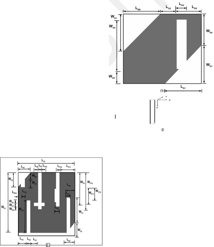
is 14.25mm and the both diagonal slots that are in triangular shape have same dimension on patch side. But on the ground plane the triangle shaped slots have slightly different dimension, which is mentioned in table 3.3. The length of slot is WP9 which width is LP12 and length of slot is WP10 which width is LP9. A small slot, which has width 0.2mm and length WP12 is associated with a slot having length WP9. The distance between upper part of slot having length WP13, and upper part of the slot having width WP7, is WP6. Distance between lower part of slot having length
1464
IJSTR©2019 www.ijstr.org
INTERNATIONAL JOURNAL OF SCIENTIFIC & TECHNOLOGY RESEARCH VOLUME 8, ISSUE 08, AUGUST 2019 |
ISSN 2277-8616 |
WP10 and lower part of slot having width WP7, is WP8.
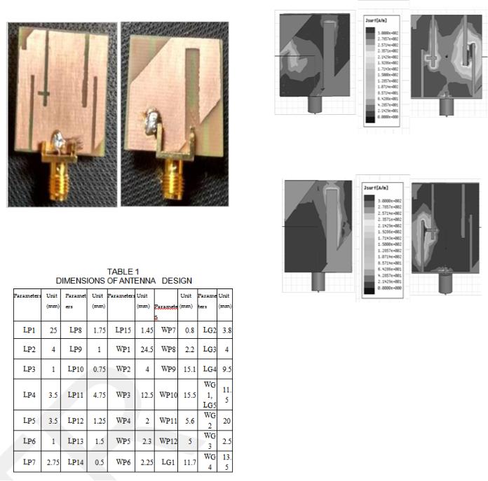
Fig.2 Fabricated dual band slotted patch antenna for LTE applications
(a) Patch plane (b) Ground plane
Fig. 3 Current densities of the proposed antenna
(a) Current density at 1.9 GHz (b) Current density at 1.9 GHz
Figure 3 shows, the simulated surface current distribution at different frequencies at 1.9 and 2.6 GHz. It is seen from figure 4 (a), the prominent surface current density is observed between the right slots. This figure also reveals that resonance (about 1.9 GHz) mainly because of region between right two slots. Figure (b) depicts the current density of resonance frequency at 2.6GHz which is due to part of the area between left slots. A small slot has been cut along Y-axis at the bottom of the slot which is adjacent to the left most slot.Specifically, the space between that small slot and the left most slot is responsible for 2.6 GHz frequency. However, slots of radiator mainly contribute to high and low resonance frequency, whereas slots at ground plane contribute coupling effect and also enhance the gain of antenna.
1465
IJSTR©2019 www.ijstr.org

INTERNATIONAL JOURNAL OF SCIENTIFIC & TECHNOLOGY RESEARCH VOLUME 8, ISSUE 08, AUGUST 2019 |
ISSN 2277-8616 |
Fig 5 Simulated input impedance of proposed antenna
From figure, it is observed that the upper band measured frequency is 1962 MHz which is 42 MHz more than required frequency. Higher frequency band is wider than required band (2570 to 2620 MHz), it starts from 2560 MHz and goes to 2645 MHz. The simulate return loss for higher band is -12.36dB and that for lower band is -13.14dB.From figure, it is seen that the measured return losses are -15 dB and - 15.2dB for lower and higher band respectively.
Fig. 4 Radiation pattern at different sampling frequencies of proposed antenna (a) 1.9 GHz (b) 2.6 GHz
Figure 4 show a far-field two-dimensional radiation patterns in the E- and H-planes at sampling frequencies of 1.9GHz and 2.60 GHz, respectively. It is found that the proposed antenna has approximately good omni-directional radiation patterns at both sampling frequencies in the E-plane (yz-plane) and the H- plane (xy-plane). The return loss of the proposed antenna is measured by an Agilent N5230A vector network analyzer. The simulation results are optimized by varying parameters of proposed antenna which is obtained by parametric study of the antenna. It is observed from figure 5, a good agreement between the measured and simulated results. The small difference between the measured and simulated results is due to the effect of SMA connector soldering, fabrication tolerance
and limitation of practical environment where antenna’sFrequency (GHz) parameters are measured.
Fig. 6 Simulated antenna gain in dB.
1466
IJSTR©2019 www.ijstr.org
INTERNATIONAL JOURNAL OF SCIENTIFIC & TECHNOLOGY RESEARCH VOLUME 8, ISSUE 08, AUGUST 2019 ISSN 2277-8616
|
|
Table II PERFORMANCE SUMMARY OF DUAL BAND |
|
|
|
|
May 2015. |
|
|
|
|
||||||||||||||||||
|
|
|
|
|
FILTERING ANTENNAS |
|
|
|
|
|
[7]. |
C. X. Mao, S. Gao, Y. Wang, F. Qin, Q. X. Chu, ―Multi- |
|||||||||||||||||
|
|
|
|
|
|
|
|
|
|
|
|
|
|
|
|
|
|
|
|
|
|
|
Mode resonator-fed dual polarized antenna array with |
|
|||||
|
|
Ref. |
|
|
Size (mm) |
|
|
Substrate |
|
|
Peak Gain (dB) |
|
|
Area (mm²) |
|
|
|
enhanced |
bandwidth |
and |
s |
||||||||
|
|
|
|
|
|
Material |
|
|
|
|
|
|
|
Transactions on Antennas and Propagation , Vol. 63, |
|
||||||||||||||
|
|
|
|
|
|
|
|
|
|
|
|
|
|
|
|
|
|
|
|
|
|
||||||||
|
[4] |
|
42 x 42 |
|
|
|
FR4 |
|
|
9.71 |
|
|
|
1764 |
|
|
|
|
No. 19, pp. 5492-5499, October 2015. |
|
|
||||||||
|
|
|
|
|
|
|
|
|
|
|
|
|
[8]. |
J. B. Jadhav, |
P. J. Deore, |
||||||||||||||
|
|
|
|
|
|
|
|
|
|
|
|
|
|
|
|
|
|
|
|
|
|
||||||||
|
[5] |
|
45 x 64 |
|
|
|
FR4 |
|
|
-1.8 /1.1 |
|
|
2880 |
|
|
|
|||||||||||||
|
|
|
|
|
|
|
|
|
|
|
|
|
radiation and filtering functions for wireless |
|
|||||||||||||||
|
|
|
|
|
|
|
|
|
|
|
|
|
|
|
|
|
|
|
|
|
|
|
|
||||||
|
[8] |
|
80 x 40 |
|
|
|
FR4 |
|
|
3.5 |
|
|
|
3200 |
|
|
|
|
applications‖, Elsevier Jou |
||||||||||
|
|
|
|
|
|
|
|
|
|
|
|
|
|
|
|
|
|
|
|
|
|
|
and Information Technology, |
pp. 125-135, October |
|
||||
|
[11] |
|
60 x 60 |
|
|
- |
|
|
9.4 |
|
|
|
3600 |
|
|
|
|
|
|||||||||||
|
|
|
|
|
|
|
|
|
|
|
|
|
2016. |
|
|
|
|
|
|||||||||||
|
|
|
|
|
|
|
|
|
|
|
|
|
|
|
|
|
|
|
|
|
|
|
|
|
|
|
|
||
|
[12] |
|
63 x 70 |
|
|
|
Roger RT |
6.7/7.3 |
|
|
4410 |
|
|
|
|
|
|
|
|
|
|||||||||
|
|
|
|
|
|
|
|
|
|
[9]. |
Y. M. Pan, P. F. Hu, X. -Y. Z |
||||||||||||||||||
|
|
Proposed |
25 x 25 |
|
|
|
FR4 |
|
|
-4.5/1.5 |
|
|
625 |
|
|
|
|
profile high-gain and wideband filtering antenna with |
|
||||||||||
|
|
Work |
|
|
|
|
|
|
|
|
|
|
|
|
metasurface‖, IEEEAntennasTransactand |
||||||||||||||
|
|
|
|
|
|
|
|
|
|
|
|
|
|
|
|
|
|
|
|
|
|
||||||||
|
|
|
|
|
|
|
|
|
|
|
|
|
|
|
|
|
|
|
|
|
|
|
Propagation, Vol. 64, No. 5, pp. 2010-2016, May |
|
|||||
|
|
|
|
|
|
|
|
|
|
|
|
|
|
|
|
|
|
|
|
|
|
|
|
||||||
5. CONCLUSION AND FUTURE SCOPE |
|
|
|
|
|
|
2016. |
|
|
|
|
|
|||||||||||||||||
The main purpose of this thesis is to design a compact printed |
[10]. C. X. Mao, S. Gao, Y. Wang, B. S. Izquierdo, Z. P. |
|
|||||||||||||||||||||||||||
|
Wang, F. Qin, Q. X. Chu, J. Z. Li, W. Gao, J. D. Xu, |
|
|||||||||||||||||||||||||||
patch antenna for use in wireless/cellular devices for LTE-A |
|
|
|||||||||||||||||||||||||||
|
―Dual-band patch antenna with filtering performance |
|
|||||||||||||||||||||||||||
band. A usual cellular phone measures about 14.5 X 4.5 cm. |
|
|
|||||||||||||||||||||||||||
|
and |
harmonic |
suppression‖,ransaction |
||||||||||||||||||||||||||
Therefore, this microstrip design must be able to fit in cellular |
|
||||||||||||||||||||||||||||
|
Antennas and Propagation, Vol. 64, Issue. 9, pp. |
|
|||||||||||||||||||||||||||
phone. As designed antenna demonstrated in chapter 3, a |
|
|
|||||||||||||||||||||||||||
|
4047-4077, September 2016. |
|
|
|
|||||||||||||||||||||||||
compact |
microstrip |
patch antenna has been successfully |
|
|
|
|
|||||||||||||||||||||||
[11]. W. Duan, X. Y. Zhang, Y. M. Pan , J. X. Xu, Q. Xu |
|||||||||||||||||||||||||||||
designed having a center frequency of 1910 and 2595 MHz. |
|||||||||||||||||||||||||||||
|
Dual polarized filtering antenna with high |
selectivity |
|
||||||||||||||||||||||||||
Different |
slots are |
|
cut in |
ground and patch |
|
plane |
for |
|
|
||||||||||||||||||||
|
|
|
and |
low |
cross |
polarization‖ |
|||||||||||||||||||||||
impedance matching. As far as, radiation pattern is concern it |
|
||||||||||||||||||||||||||||
|
Antennas and Propagation, Vol. 64, No. 10, pp. 4188- |
|
|||||||||||||||||||||||||||
is almost omn-idirectional but gain can be further improved. |
|
|
|||||||||||||||||||||||||||
|
4196, October 2016. |
|
|
|
|||||||||||||||||||||||||
Due to limitation of |
feeding |
structure, |
width of the patch is |
|
|
|
|
||||||||||||||||||||||
[12]. X.Y Zhang, Y. Zhang, -ProfileY. Pan, |
|||||||||||||||||||||||||||||
important consideration and |
soldering |
should be |
proper |
for |
|||||||||||||||||||||||||
|
dual band filtering patch antenna application to LTE |
|
|||||||||||||||||||||||||||
accurate result. Any other feeding technique of |
Microstrip |
|
|
||||||||||||||||||||||||||
|
MIMO System‖, |
IEEE |
Transact |
||||||||||||||||||||||||||
patch antenna can be realized using different techniques for |
|
||||||||||||||||||||||||||||
|
Propagation, Vol. 65, No. 1, |
pp. 103-113, January |
|
||||||||||||||||||||||||||
feeding like edge feeding , inset feeding , aperture coupling |
|
|
|||||||||||||||||||||||||||
|
2017. |
|
|
|
|
|
|||||||||||||||||||||||
feeding |
and proximity feeding |
in future designs for |
this |
|
|
|
|
|
|
||||||||||||||||||||
[13]. Anitha P, A. S. R. Reddy, M. N. G. Prasad, ―Design of |
|
||||||||||||||||||||||||||||
proposed antenna.The material of substrate (e.g Rogers RT |
|
||||||||||||||||||||||||||||
|
a Compact Dual Band Patch Antenna with Enhanced |
|
|||||||||||||||||||||||||||
Duroid 5880) and height of substrate can be changed. |
|
|
|
|
|
||||||||||||||||||||||||
|
|
|
|
Bandwidth on ModifiedInternationalGroun |
|||||||||||||||||||||||||
|
|
|
|
|
|
|
|
|
|
|
|
|
|
|
|
|
|
|
|
|
|
|
|||||||
REFERENCES |
|
|
|
|
|
|
|
|
|
|
|
|
|
|
|
|
|
Journal of Applied Engineering Research, Vol.13, No. |
|
||||||||||
|
|
|
|
|
|
|
|
|
|
|
|
|
|
|
|
|
1. pp. 118-122, 2018. |
|
|
|
|||||||||
[1]. |
C. T. Chuang, |
S. J. Chung, |
|
|
|
||||||||||||||||||||||||
―A |
compact printed |
|
― |
||||||||||||||||||||||||||
|
|
|
filtering antenna using a ground-intruded coupled line |
[14]. J. Meena, K.Gautam and P.K. SlottedSharma,Patch |
|||||||||||||||||||||||||
|
|
|
|
Antenna for X- Band |
Applications‖,International |
||||||||||||||||||||||||
|
|
|
resonator‖, |
|
IEEE |
|
|
|
|
|
|
||||||||||||||||||
|
|
|
|
|
TransactionAntennas |
and |
Research |
and |
Analytical |
|
|||||||||||||||||||
|
|
|
Propagation, Vol. 59, No. 10, pp. 3630–3637, October |
|
Journal |
of |
|
||||||||||||||||||||||
|
|
|
|
Reviews,Vol.6,Issue 1,pp.974-977,Mar. 2019. |
|
||||||||||||||||||||||||
|
|
|
2011. |
|
|
|
|
|
|
|
|
|
|
|
|
|
|
|
|
|
|
||||||||
|
|
|
|
|
|
|
|
|
|
|
|
|
|
|
|
|
|
|
|
|
|
|
|
|
|
||||
[2].Z. Zakaria, W. Y. Sam, M. Z. A. Aziz, M. A. Said, ―Microwave filter and antenna for wireless
communication systems‖,Symposium on IEEE
Wireless Technology and Applications, pp. 7580, September 2012.
[3].G. Mansour, M.J. Lancaster, P.S. Hall,P.Gardner,E.
Nugoolcharoenlap, ― Design offiltering microstrip antenna using filter synthesis approach‖, Progress in
Electromagnetics Research,Vol. 145, pp. 59–67, February 2014.
[4].X. Y. Zhang, W. Duan,-gain filteringY. M. Pan, ―High
patch antenna without extra circuit‖, IEEE
Transactions on Antennas and Propagation, Vol. 63, No. 12, pp. 5883-5888, December 2015.
[5].C. Y. Hsieh, C. H. Wu, -T. G. Ma, ―A compact dual band filtering patch antenna using step impedance
resonators‖, IEEE WirelessAntennas and
Propagation, Vol. 14, pp. 1056–1059, May 2015.
[6].H. Chu, C. Jin, J. X. Chen, Y. X. Guo, ―A 3D millimeter-wave filtering antenna with high selectivity
and low cross-polarization‖, IEEE Transactions on
Antennas and Propagation, Vol. 63, pp. 2375-2380,
1467
IJSTR©2019 www.ijstr.org
View publication stats