

диафрагмированные волноводные фильтры / 34573669-0fe2-4822-9b8b-9575a94c3994
.pdf2013 International Workshop on Microwave and Millimeter Wave Circuits and System Technology
Rectangular Waveguide Band-pass Filter with Harmonic Suppression
Yucui Li, Qingyuan Wang, and Congling Wang
School ofPhysical Electronics, University ofElectronic Science and Technology ofChina, lianshe North Avenue, Chengdu 610054, China
Abstract - An improved structure of rectangular waveguide band-pass filter with harmonic suppression is proposed. The filter consists of cascade resonant cavities with coupling provided by irises. By means of varying the width of each resonator and the offsets between the adjacent resonant cavities, the stop-band was successfully pushed to a two octaves frequency range. The results show that the designed rectangular waveguide band-pass filter has a pass band of 27.5 GHz - 30 GHz and stop-band suppression of greater than 33 dB over the frequency range from 35 GHz to 60 GHz, its pass-band insertion loss is less than 0.1 dB, return loss is more than 19 dB. The filter can be used in modern communication systems with the requirement of harmonic suppression.
Index Terms - band-pass filter, communication systems, harmonic suppression, rectangular waveguide.
I. INTRODUCTION
Waveguide filters play an important role in modern communication systems such as radar and satellite communications. The rapid development of modern communication systems entails accurate design of waveguide filters. Filters' stop-band attenuation is required to meet higher demand. A number of approaches have been proposed in order to improve the stop-band performance. In fact, in 1964 H. 1. RIBLRT applied for a patent of waveguide filter with suppression of parasitic pass-band[l]. The approach in this patent is to maintain the rectangular shape and simply vary the width of each resonator. The analysis of the filter is relatively easy as the resonant modes of a rectangular waveguide resonator are preserved. However the patent didn't give the best inhibition curves, but offered an inspired approach. Then Raju Balasubramanian and Protap Pramanicktichu put forward computer aided design method on this type of filter in 1998[2]. They designed a four cavities filter working in 10 GHz which broaden the parasitic pass band from 16.5 GHz to 17.5 GHz. In 2002 Marco Morelli elaborated how to choose the width of each resonator in order to satisfY the parasitic pass-band requirements and carried out a detailed analysis and comparison. He successfully pushed the parasitic pass-band to two octaves outside[3]. In the above designs, they all adopted symmetrical structure. In this paper, we put forward an improved asymmetric structure which are more compact
as well as broadening the stop-band to a two octaves frequency range. As a cavity filter, it can achieve low loss and have high power handling capabilities.
II. FILTER DESIGN AND SIMULATION RESULTS
Rectangular waveguide structures enclosed by two discontinuities are often used in the design of band-pass filters[4]. In this paper, we adopted cascade resonant cavities structure with direct coupling provided by irises. The final three-dimensional structure of the rectangular waveguide band-pass filter with broad stop-band is given in Fig. 1. The same height of all resonators is, h=3.56mm, as shown in the Fig. 1.
Fig.l. Three-dimensional structure of the rectangular waveguide band-pass filter.
In the configuration all resonators have the fundamental resonant frequency at ro, the centre frequency of the proposed filter. The second resonant frequency fl can be controlled by the width of resonators, through correctly chosen, the stop-band performance of the filter can be further improved.
The proposed filter adopted asymmetric structure and realized a smaller size compared with the filter proposed in paper[l]. And Fig. 2 shows the front view of our original design structure. We numbered the resonators consecutively from 1 to 9 as shown in Fig. 2. The width parameters of resonators are represented by a(i)(i=1,2...,9) respectively, and the length parameters are represented by b(i)(i=1,2...,9). Then the offset parameters between the adjacent resonant cavities are off(i)(i=1,2,...,9) which are marked in Fig. 2. Carefully select the initial value, then we do optimization with the uWave software, the stop band was successfully pushed to two octaves outside, and the simulation results of the initial design structure are
978-1-4673-5504-9/13/$31.00 ©2013 IEEE |
251 |
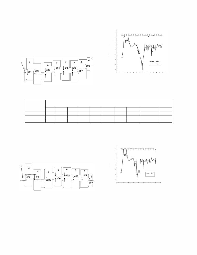
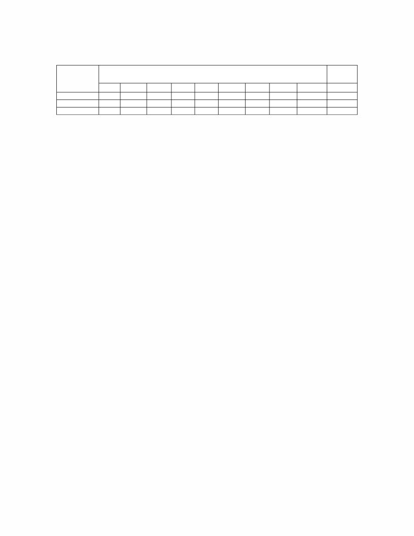
TABLE II
PARAMETER VALUES OF THE FINAL DESIGN STRUCTURE
parameters |
|
|
|
|
Number_ i |
|
|
|
|
|
|
|
|
|
|
|
|
|
|
|
|
(mm) |
0 |
1 |
2 |
3 |
4 |
5 |
6 |
7 |
8 |
total |
|
||||||||||
a(i) |
7.11 |
12.13 |
11.28 |
10.46 |
10.47 |
11.14 |
11.37 |
9.85 |
7.11 |
|
I(i) |
1 |
4.56 |
4.96 |
5.15 |
5.08 |
5.2 |
5.16 |
4.89 |
2 |
|
off(i) |
|
3.04 |
-2.77 |
0.8 |
1.1 |
-0.63 |
-0.56 |
0.08 |
-1.06 |
0 |
From TABLE II, we can see the total offset is zero, it means the input and output ports are symmetric which are more adaptive in the general fabrication. The improved structure is easier to fabrication and successfully extend the parasitic pass-band to more than two times the center frequency of 4)=28.75 GHz. The input/output ports are designed as R320 standard waveguide.
III. CONCLUSION
In this paper, we designed and optimized a rectangular waveguide band-pass filter with the pass band of 27.5 GHz -30 GHz and stop-band suppression of greater than 33 dB over the frequency range from 35 GHz to 60 GHz, successfully broaden the suppression to a two octaves frequency range. We can't give the test results in this paper because the filter is in the processing. when the processing done, we will do the installation and testing. This filter with improved asymmetric structure can be fabricated easily and successfully with a more compact structure compared with the filter proposed in paper[l]. Cavity structures
have the advantages of low loss and high power handling capabilities compared with ridged-waveguide resonator structures[5], so it can be more adaptive in high power communication systems with the requirement of harmonic suppression.
REFERENCES
[1]H.J.Riblet, "Waveguide Filter having Nonidentical Sections Resonant at Same Fundamental Frequency and Different Harmonic Frequencies", U.S. Patent 3153208, Oct 1964.
[2]R.Balasubramanian, P.Pramanick, "Computer Aided Design of H-Plane Tapered Corrugated Waveguide Bandpass Filters",John Wiley & Sons, Int J RF and Microwave CAE 9, pp. 14-21, 1999.
[3]Morelli, M. , Hunter, I. , Parry, R. and Postoyalko, V., " Stop-band improvement of rectangular waveguide filters using different width resonators: selection of resonator widths ", Microwave Symposium Digest, 2001 IEEE MTT-S International Vol. 3, pp. 1623 - 1626, 2001.
[4]David M. Pozar, "Microwave Engineering Third Edition", pp. 90-100, 2006.
[5]D.Budimir, "Optimized E-Plane Bandpass Filters with Improved Stopband Performance", IEEE naris. Microwave Theory Techniques, vol. MTT-45, No. 2, pp.212-220, Feb 97.
253