

диафрагмированные волноводные фильтры / 02513158-77b5-4cb6-b814-5625cc3c4c5a
.pdfInternational Journal of Electronics and Computer Science Engineering |
360 |
|
Available Online at www.ijecse.org |
ISSN- 2277-1956 |
|
Design and Comparison of Reconfigurable Perfectly-
Matched Bandstop Filters
B. H. Ahmad 1 , M. K. Zahari 2 , Peng Wen Wong 3
1,2 Centre for Telecommunication Research & Innovation (CeTRI), Faculty of Electronics and Computer Engineering, Universiti Teknikal Malaysia Melaka (UTeM), Hang Tuah Jaya, 76100 Durian Tunggal, Melaka, Malaysia.
3Electrical & Electronic Engineering Department,
Universiti Teknologi Petronas (UTP), Bandar Seri Iskandar, 31750 Tronoh, Perak, Malaysia. 1badrulhisham@utem.edu.my
AbstractThis paper discusses two new designs of reconfigurable perfectly-matched bandstop filter which is based on L-shape and ring resonator. The perfectly-matched bandstop filters can be reconfigured between allpass and bandstop response using PIN diodes as switching elements. The operating center frequency of these filters is at 1 GHz. The discussions of the conceptual perfectly-matched bandstop filters are included in this paper. The filters have been simulated for analysis where the effect of microstrip line and FR4 substrate has been taken into account. It is then further fabricated and measured for verification. The filters will then be compared in terms of s-parameter and size. Result shows good agreement between simulation and measurement.
Keywords – reconfigurable filter, matched bandstop filter, allpass to bandstop
I. INTRODUCTION
The increasing development of microwave and millimeter-wave communication system has promoted the need for suppression of multiple unwanted signals for military broadband applications [1]. Thus, high performance and miniaturize size of bandstop filter is investigated. Bandstop and bandpass filters [2-4] play an important role in microwave and millimeter-wave system, which are applied to discriminate the desired and unwanted signals. Bandstop filters also are the components in microwave communication front-end which is used to isolate frequency band located within a wide pass-band.
Bandstop filter provides an overhaul of communication system that contains unwanted signal or interferences. Bandstop filter can be applied in an active element circuit design such as mixer and oscillator to remove higher order harmonics and other spurious signal where it is usually implemented in RF transmitter [5] and receiver [6] design. For an ideal bandstop filter, an attenuation of frequencies will occur at above its lower cut-off frequencies and below its upper cut-off frequencies. On the other hand, for frequencies greater than the upper cutoff and frequencies less than the lower cutoff the signal is allowed to pass which known as pass-band region.
At present, demand for high performance and reconfigurable bandstop filter is a necessity in many communication applications. The reconfigurable filters can be reducing the complexity of a system by allowing filter re-configurability instead of having switched filter banks. Moreover, implementation of a notch concept of the filter producing a maximum attenuation for bandstop filters as shown in Figure 1. This is used to remove a narrow band of frequencies from the signal path [7].
ISSN: 2277-1956/V2N1-360-369

361
Design and Comparison of Reconfigurable Perfectly-Matched Bandstop Filters
Figure 1. Notch bandstop frequency response.
However, losses in the system material or the appearance of an active device such as diode [8] affect the quality factor of the filter. Normally response of the input reflection (S11) and forward transmission coefficient (S21) in the conventional bandstop filter is shown in Figure 1. The S11 is the input reflection where the input energy is reflected back to an input port. Thus, this condition is bad because the reflected energy could damage the input device. It is better to have a response that will forward the entire signal to the output. That's known as a matched bandstop filter.
For that reason, the reconfigurable matched bandstop filter is proposed based on the implementation of perfectly-matched bandstop filter to overcome this drawback. In [9], it proved that the network is perfectlymatched and give a bandstop response with maximum attenuation at center frequencies even by applying lossy resonator circuit. In [10] showed the switchless second-order bandstop filters that use series-coupled resonators to achieve bandstop-to-all-pass operation.
Therefore, this paper discusses two new designs of reconfigurable perfectly-matched bandstop filter which are based on L-shape resonator and ring resonator. These designs are the extension of the perfectly-matched matched bandstop filter that first introduced in [9] to produce a high Q of lossy resonator. Although there are several works on the tunable matched bandstop filter reported in [11], [12] and [13], this paper introduces perfectly-matched bandstop filters to be reconfigured between allpass and bandstop response using PIN diodes.
This paper is organized as follows. The discussion of the theory and design of perfectly-matched bandstop filters using L-shape and ring resonator are highlighted in Section II. This includes the analysis of reconfigurable between allpass and bandstop response. Section III discusses the experimental results of the reconfigurable perfectly-matched bandstop filters. Finally, conclusion is given in Section V.
II. THEORY AND DESIGN OF PERFECTLY-MATHCED BANDSTOP FILTERS
This session divide into two, which is explanation about theory of perfectly-matched bandstop filter and the design of L-shape and ring resonator for matched bandstop filter.
I.Theory of Perfectly-Matched Bandstop Filter
Perfectly-matched bandstop is realized at high frequencies where the lossy nature of microstrip makes it difficult to achieve a high Q factor. The perfectly notched concept [9] is applied to improve the Q factor of bandstop limiter in this design. Based on a reflection mode filter, this concept makes use of two identical lossy resonators coupled to a 3-dB 90° hybrid coupler with correct coupling fac tors. At the center frequencies, the incident signals are critically coupled to the resonators and absorbed in the resistive part of the resonator leaving no reflected signals at the output, thus achieving a theoretically infinite attenuation [8].
One of the practical implementation of lossy allpass network is a bandstop limiter. The filter design is implementing the concept of coupler-resonator model which presenting a matched bandstop filter based on L-shape resonator. The generalized coupled-resonator model of a perfectly matched bandstop obtained by scaling nodes of the admittance matrix of 90̊hybrid circuits, where the even-odd mode admittance analysis can be shown as in [9]. The generalized equation for the perfectly matched bandstop filter is as shown in (1) and (2).
ISSN: 2277-1956/V2N1-360-369

IJECSE, Volume2, Number 1 |
362 |
B. H. Ahmad et al. |
|
Figure 2. Generalized coupled-resonator model of a matched notch filter.
(1)
and
(2)
II.Design of Matched Bandstop Filter using L-shape Resonator
This design of the matched bandstop filter consist the two parallel-coupled  Short circuit transmission lines
that produced a nominally-90̊-phase shift element between the resonator couplings in one structured. Figure 3 is a coupled resonator design with the desired parameter for the matching bandstop filter.
Figure 3. Coupled resonator design with the desired parameter for the matching bandstop filter.
The design specification of matched bandstop filter based on L-shape resonator is referring to the Table 1. This specification is used for the reconfigurable matched bandstop filter which is designed at center frequency of 1 GHz. Perfectly notch topology with lossy resonator is implemented in this project to achieved matched bandstop response between S11 and S12 at one resonance frequency. K2 equal to 1 where 1 is considered as 90̊length. The value of K1 gap will be tuned gradually to make sure the two modes can be overlapped each other and achieved cancellation to produce a notch bandstop.
Table 1. Design specification.
Substrate |
FR4 board |
Substrate thickness |
1.6 mm |
Dielectric constant, |
4.7 |
Loss tangent |
0.019 |
Operating frequency |
1 GHz |
The reconfigurable matched bandstop filter is designed by adding switching elements to the filter. Switching elements consist of the PIN diode, biasing line, chip capacitor and resistor. The filter will attach with biasing line.
ISSN: 2277-1956/V2N1-360-369

363
Design and Comparison of Reconfigurable Perfectly-Matched Bandstop Filters
The biasing line is used as the inductance for the PIN diodes. Chip capacitor also will attach to the biasing line. It is for current limiter purpose.
III.Design of Matched Bandstop Filter using Ring Resonator
Figure 4 consist of a ring resonator coupled with thru line. Dual mode designs is coupled into the two modes 90° out of phase, effectively setting up a single w ave circulating around the resonator. At resonance the power coupled off from the resonator at the output is equal in power and 180° out of phase with the signal e xiting the thruline and a perfect notch is produced.
Figure 4. Traveling-wave interpretation of the dual-mode ring resonator notch. The two modes of the resonator are excited at 90° out of phase, resulting in a single circulating wave.
Dual mode ring resonator structure is composed of two degenerate modes or splitting resonant frequencies that may be excited by perturbing stubs, notches or symmetrical feed lines. The ring resonator with a perturbing stub or notch at Φ = 45̊, 135,̊225̊, or 315̊. In this project the stub is located at 135̊as shown in Figure 5.
Figure 5. Perturbing stub at 135°.
Ring resonator is two identical λg/2 resonator connected in parallel. Two identical resonators are excited and produce the same frequency response, which overlapped each other if the ring does not have any perturbing and is excited by symmetrical feed lines,. However, if one of the λg/2 is perturbing out of balance with the other, two different frequency modes are excited and coupled to each other.
IV. Analysis of Reconfigurable between Allpass to Bandstop
The schematic design consists of Microstrip Couple Line (MCLIN) for the gap of coupled resonator, Microstrip Line (MLIN), Microstrip Bend (Bend) and Terminal (Term) for the input/output port. PIN diodes in this
ISSN: 2277-1956/V2N1-360-369

IJECSE, Volume2, Number 1 |
364 |
B. H. Ahmad et al. |
|
simulation is using commercialize diode model. The switching element of this filter included with Inductor, chip capacitor, resistor, power supply and PIN diode as shown in Figure 6.
Vbias1 |
Vbias2 |
Port A |
Port B |
Input |
Output |
Figure 6. Schematic testing of |
matched bandstop filter based on L-shape resonator with PIN diode. |
Figure 7. Matched bandstop response when PIN diode in OFF state.
Figure 8. Allpass response when PIN diode in ON state.
ISSN: 2277-1956/V2N1-360-369
365
Design and Comparison of Reconfigurable Perfectly-Matched Bandstop Filters
Vbias1 |
Vbias2 |
Port A |
Port B |
Input |
Output |
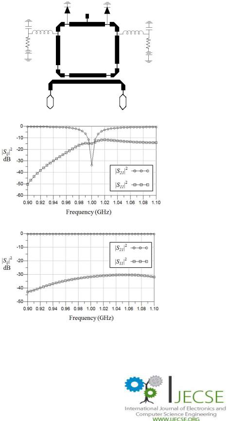
Figure 9. Schematic testing of reconfigurable matched bandstop filter using ring resonator with PIN diode.
Figure 10 Matched bandstop responses when the PIN diode in reverse biased.
Figure 11. Allpass response when PIN diode in forward biased.
III. EXPERIMENTAL RESULT
As depicted in Figure 12, the reconfigurable matched bandstop filter based on L-shape resonator is fabricated on FR4 board and assembled together with PIN diodes, RF chokes, inductors and SMA connectors. The grounding area
ISSN: 2277-1956/V2N1-360-369

IJECSE, Volume2, Number 1 |
366 |
B. H. Ahmad et al. |
|
made wide this is to make sure that the entire RF/microwave signal properly grounded. From the result as shown in Figure 13, can see that the attenuation level is increase for S21 is -15 dB and S11 is still below -10 dB which is still under consideration. The response for the S21 is shifted about 500 MHz from 1 GHz.
Figure 12. Reconfigurable matched bandstop filter using L-shape resonator.
Figure 13. Measurement of matched bandstop filter when PIN diode turn OFF.
Figure 14. Measurement of the matched bandstop filter when PIN diode turn ON.
Figure 15 shows the reconfigurable matched bandstop filter using ring resonator. The biasing network consisted of biasing line or RF choke/inductor, chip capacitor and resistor. Chip capacitor that used in this prototype is 0805
ISSN: 2277-1956/V2N1-360-369

367
Design and Comparison of Reconfigurable Perfectly-Matched Bandstop Filters
COG ceramic capacitors, 100pF 50V. Inductor that used in this design is Inductor SMD 0402 47 nH, 300 mA and the resistor used is 110Ω.
Figure 15. Reconfigurable matched bandstop filter using ring resonator.
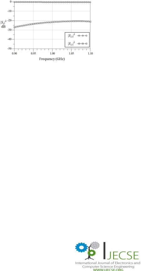
This circuit is tested under two conditions. First, the PIN diode will forward bias to turn the PIN diode ON by giving +5V to maximum +25V. Secondly, the PIN diode will reverse bias to turn the PIN diode OFF by giving -5V to maximum -25V. When the PIN diode is turn ON, the filter will produce Allpass response and when the PIN diode is turn OFF, the filter will produce a matched bandstop response as shown in Figure 16 and 17.
Figure 16. Measurement result of matched bandstop filter using ring resonator when reverse biased (PIN diode OFF state).
ISSN: 2277-1956/V2N1-360-369
IJECSE, Volume2, Number 1 |
368 |
B. H. Ahmad et al. |
|
Figure 17. Measurement result of matched bandstop filter using ring resonator when forward biased (PIN diode ON state).
As observation, ring resonator significantly can reduce the circuit size of matched bandstop filter compeered to L-shape resonator. Based on Table 2, shows the comparison of matched bandstop filter based on L-shape and ring resonator. As shown in the table, the Q factor for ring resonator is higher than L-shape where 83 and 66.67 respectively. But when comes to fabrication, the measurement result shows that L-shape 71.43 and ring resonator only give 22.72. These maybe because effect of the PIN diode and the biasing circuit to the ring resonator structure.
Table 2. Comparison of Matched bandstop filter based on L-shape and ring resonator.
|
Matched Bandstop Filter |
Matched Bandstop Filter |
|||
Parameter |
based on L-shape Resonator (size = |
based on Ring Resonator (size = 700mm x |
|||
105mm x 92mm) |
|
850mm) |
|||
|
|
||||
|
Simulation |
Measurement |
Simulation |
|
Measurement |
Bandstop Response |
14.68 |
27.50 |
14.89 |
|
10.16 |
(S11), dB |
(< -10) |
|
(< -10) |
|
|
Bandstop Response |
27.25 |
15.44 |
33.73 |
|
10.16 |
(S21), dB |
|
|
|
|
|
Q factor |
66.67 |
71.43 |
83 |
|
22.72 |
ISSN: 2277-1956/V2N1-360-369

369
Design and Comparison of Reconfigurable Perfectly-Matched Bandstop Filters
IV.CONCLUSION
Reconfigurable perfectly-matched bandstop filter based on L-shape and ring resonator have been proved through this paper that is able to switch from bandstop response to all pass response which are allows the construction of reconfigurable by adding PIN diode as switching elements. The simulation and measurement result have shown that the circuit can be reconfigured between bandstop to allpass by using two PIN diodes at K2 coupling in the dual-mode ring resonator. The comparison is made between these two designs in term of s-parameter and circuit size. The theory of such a filter was developed through the use of coupling gap K1 and K2 such that only the resonator center frequencies need to be tuned in order to achieve bandstop to allpass. As the conclusion, matched bandstop filter based on L-shape resonator have high Q factor and give a narrow attenuation level than ring resonator.
V.ACKNOLEDGEMENT
We would like to acknowledge the contribution of our colleagues from Fabrication and Microwave Laboratory, Faculty of Electronics and Computer Engineering, UTeM for fabrication and measurement of the research works.
References
[1]Han, S. H., X. L. Wang, and Y. Fan, Improved generalized admittance matrix technique and its applications to rigorous analysis of millimeter-wave devices in rectangular waveguide. International Journal of Infrared and Millimeter Waves, Oct. 2006
[2]Ni, D., Y. Zhu, Y. Xie, et al., Synthesis and design of compact microwave filters with direct source-load coupling. Journal of Electromagnetic Waves and Applications
[3]Jin, L., C. L. Ruan, and L. Y. Chun, Design E-plane bandpass filter based on EM-ANN model. Journal of Electromagnetic Waves and Applications, 2006
[4]Zhang, J. J., Z. Gu, B. Cui, and X. W. Sunc, Compact and harmonic suppression open-loop resonator bandpass filter with trisection SIR.
Progress In Electromagnetic Research, PIER, 2007
[5]Shairi, N.A.; Abd Rahman, T.; Abd Aziz, M.; , "RF transmitter system design for Wireless Local Area Network bridge at 5725 to 5825 MHz," Computer and Communication Engineering, 2008. ICCCE 2008. International Conference on , pp.109-112, 13-15 May 2008.
[6]Shairi, N.A.; Rahman, T.A.; Aziz, M.Z.A.; , "RF receiver system design for Wireless Local Area Network bridge at 5725 to 5825 MHz,"
Applied Electromagnetics, 2007. APACE 2007. Asia-Pacific Conference on, pp.1-6, 4-6 Dec. 2007.
[7]Jachowski, D.R., "Passive enhancement of resonator Q in microwave notch filters," Microwave Symposium Digest, 2004 IEEE MTT-S International , vol.3, no., pp. 13151318 Vol.3, 6-11 June 2004.
[8]Hunter I. C., 2001 Theory and Design of Microwave Filters, Bodmin, Cornwall, MPG Books Limited.
[9]Guyette, A.C., Hunter, I.C., Pollard, R.D., Jachowski, D.R.,. "Perfectly-matched bandstop filters using lossy resonators". Microwave Symposium Digest, 2005 IEEE MTT-S International , 12-17 June 2005.
[10]Naglich, E.J.; Juseop Lee; Peroulis, D.; Chappell, W.J.; , "Switchless Tunable Bandstop-to-All-Pass Reconfigurable Filter," Microwave Theory and Techniques, IEEE Transactions on , vol.60, no.5, pp.1258-1265, May 2012.
[11]Jachowski, D.R.; , "Compact, frequency-agile, absorptive bandstop filters," Microwave Symposium Digest, 2005 IEEE MTT-S International , vol., no., pp. 4 pp., 12-17 June 2005.
[12]Peng Wen Wong; Hunter, I.C.; Pollard, R.D.; , "Matched bandstop resonator with tunable K-inverter," Microwave Conference, 2007. European , vol., no., pp.664-667, 9-12 Oct. 2007.
[13]Jachowski, D.R.; Guyette, A.C.; , "Sub-octave-tunable microstrip notch filter," Electromagnetic Compatibility, 2009. EMC 2009. IEEE International Symposium on , vol., no., pp.99-102, 17-21 Aug. 2009.
ISSN: 2277-1956/V2N1-360-369