

диафрагмированные волноводные фильтры / 668174ca-e50d-45fc-bbda-24f94101536e
.pdfIEEE TRANSACTIONS ON MICROWAVE THEORY AND TECHNIQUES, VOL. 50, NO. 7, JULY 2002 |
1657 |
Stopband Performance Improvement of Rectangular
Waveguide Filters Using Stepped-Impedance
Resonators
Marco Morelli, Ian Hunter, Richard Parry, and Vasil Postoyalko
Abstract— Rectangular waveguide stepped-impedance resonators (SIRs) are analyzed and employed in the design of an  -band filter with center frequency
  0 = 10 GHz and a bandwidth of 100 MHz. An attenuation of 80 dB is held up to 23.1 GHz and, compared to standard uniform-impedance-resonator filters, a reduction in length of 55% is achieved at the expense of an increased insertion loss from 0.6 to 1.5 dB. The second resonance of the fundamental TE10 mode can be controlled by adjusting the length and impedance ratio of each resonator. A design procedure that takes into account step discontinuities is described and applied to the design of a number of SIR filters. Finally, the presented theory is supported with experimental results.
Index Terms— Rectangular waveguides, stepped-impedance resonators, stopband improvement of filters, waveguide filters.
I. INTRODUCTION
THE demand for microwave filters having better and better performances and low production costs is ever increasing in the fast-growing wireless communication markets. The
development of new solutions is dictated by the need for more stringent requirements on both in-band and out-of-band performances: low loss, high selectivity, high rejection, wide spurious-free frequency ranges, and so forth. In particular, when out-of-band rejections are concerned, distributed microwave filters usually present unwanted spurious transmissions whose level might be unsatisfactory in some instances. In order to recover the required level of rejection, a low-pass filter is usually employed, leading to higher cost and complexity in the manufacture of microwave filters.
Unlike lumped-element bandpass filters where all resonant structures resonate at only one frequency, distributed bandpass filters have resonant structures that exhibit not one, but a number of resonances. The reasons for this are as follows:
•the fundamental mode of propagation of the guiding structure used to build the filter resonates when the electrical length of a resonator satisfies a certain resonance condition; due to the periodic nature of distributed elements, this condition yields more than one solution;
•as well as the fundamental mode, higher order modes are present and they show the same kind of unwanted resonances.
Manuscript received August 7, 2000; revised July 26, 2001.
The authors are with Filtronic Plc (U.K.), Leeds BD17 7SW, U.K. and also with the School of Electronic and Electrical Engineering, The University of Leeds, Leeds BD17 7SW, U.K.
Publisher Item Identifier 10.1109/TMTT.2002.800381.
A number of approaches have been proposed in order to reduce such spurious transmissions in microwave filters. As far as rectangular waveguide  -plane filters are concerned, improved stopband attenuation can be achieved by employing either wider or narrower resonators (or thicker inserts), depending on the position of the passband within the fundamental

 mode range [1]. Alternatively, ridged waveguide resonators can be employed [2]. However, these approaches can provide sufficient attenuation only up to frequencies around 1.4 times the center frequency of the filter. The use of multiple inserts [3] can extend the spurious-free frequency range up to half an octave (i.e., 1.5 times the center frequency), but it also leads to a higher degree of complexity.
Better stopband performance (attenuation up to 


 ) can be achieved by using inductive irises and resonators having different transversal dimensions [4], [5], so that they all resonate at the same fundamental frequency (the center frequency of the filter), but at different harmonic frequencies.
The use of stepped-impedance resonators (SIRs) [6] is based on the same principle and improved stopband performances of parallel coupled stripline filters [7] and comb-line filters [8]–[10] have been achieved.
In this paper, the resonant properties of SIRs are exploited in the design of rectangular waveguide filters with improved stopband performance. An accurate design procedure is outlined and a number of theoretical and experimental results are given.
II. RESONANT PROPERTIES OF SIRS
All resonant frequencies of a uniform-impedance resonator (UIR)are determined by the length of the resonator itself, which represents the only degree of freedom of the structure. In other words, the fundamental resonant frequency  is controlled by the length of the resonator, but also all the higher resonant frequencies are fixed. If more degrees of freedom are added, then more resonant frequencies can be controlled.
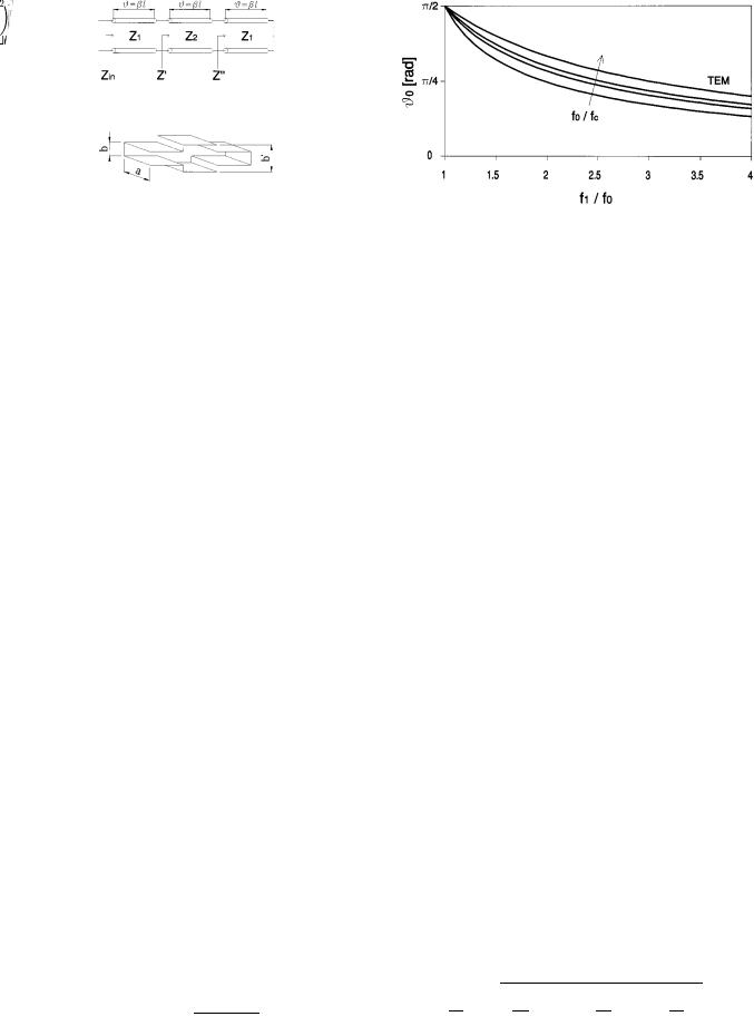
In this paper, the interest will be focused on the ability to control the second resonance; hence, only one extra degree of freedom is required. For this purpose, the symmetrical SIR shown in Fig. 1 will be analyzed. The physical length  of each section and the ratio between the two impedances
(1)
are the two parameters that can be adjusted to control the fundamental and the second resonant frequencies.
0018-9480/02$17.00 © 2002 IEEE
1658 |
IEEE TRANSACTIONS ON MICROWAVE THEORY AND TECHNIQUES, VOL. 50, NO. 7, JULY 2002 |
Fig. 1. SIR (ignoring step discontinuities).
Fig. 2. Rectangular waveguide E-plane SIR (Z =Z
=Z = b
= b =b).
=b).
|
|
|
|
|
|
|
|
|
|
|
|
Fig. 3. Fundamental resonant electrical length for a TEM resonator (f |
= 0) |
|||||||||||||||||||||||||||||||
|
As far as rectangular waveguide resonators are concerned, |
and a waveguide resonator (f |
=f |
= 1:25; 1:50; 1:75). |
|
|
|
|
|
|
|
|
|
|||||||||||||||||||||||||||||||
changes of impedance can be realized by -plane or -plane |
|
|
|
|
|
|
|
|
|
|
|
|
|
|
|
|
|
|
|
|
|
|
|
|
|
|
|
|
|
|
|
|
||||||||||||
steps. For an -plane SIR, the cutoff frequencies of the inner |
The electrical lengths |
and |
are related by |
|
|
|
|
|
||||||||||||||||||||||||||||||||||||
section and the outer sections are different. In order to keep |
|
|
|
|
|
|||||||||||||||||||||||||||||||||||||||
|
|
|
|
|
|
|
|
|
|
|
|
|
|
|
|
|
|
|
|
|
|
|
|
|
|
|
|
|
|
|
|
|||||||||||||
the fundamental mode in propagation in each section while pre- |
|
|
|
|
|
|
|
|
|
|
|
|
|
|
|
|
|
|
|
|
|
|
|
|
|
|
|
|
|
|
|
|
||||||||||||
venting the higher order modes from propagating at the center |
|
|
|
|
|
|
|
|
|
|
|
|
|
|
|
|
|
|
|
|
|
|
|
|
|
|
|
|
|
|
|
(9) |
||||||||||||
|
|
|
|
|
|
|
|
|
|
|
|
|
|
|
|
|
|
|
|
|
|
|
|
|
|
|
|
|
|
|
||||||||||||||
frequency of the filter, the ratio between the two broad dimen- |
|
|
|
|
|
|
|
|
|
|
|
|
|
|
|
|
|
|
|
|
|
|
|
|
|
|
|
|
|
|
|
|
||||||||||||
sions is limited. As a consequence, the impedance ratio (1) is |
where |
|
and |
are the fundamental and second resonant fre- |
||||||||||||||||||||||||||||||||||||||||
also restricted to a limited range. Indeed, for an -plane SIR, |
|
|||||||||||||||||||||||||||||||||||||||||||
quencies, respectively. Therefore, by substituting (9) into (8), it |
||||||||||||||||||||||||||||||||||||||||||||
this constraint does not hold and a wider range of impedance |
||||||||||||||||||||||||||||||||||||||||||||
follows that |
|
|
|
|
|
|
|
|
|
|
|
|
|
|
|
|
|
|
|
|
|
|
|
|
|
|
|
|
|
|||||||||||||||
ratios is achievable. Hence, the interest will be focused on an |
|
|
|
|
|
|
|
|
|
|
|
|
|
|
|
|
|
|
|
|
|
|
|
|
|
|
|
|
|
|||||||||||||||
|
|
|
|
|
|
|
|
|
|
|
|
|
|
|
|
|
|
|
|
|
|
|
|
|
|
|
|
|
|
|
|
|||||||||||||
|
-plane SIR, which is shown in Fig. 2. |
|
|
|
|
|
|
|
|
|
|
|
|
|
|
|
|
|
|
|
|
|
|
|
|
|
|
|
|
|
|
|
(10) |
|||||||||||
A. Ideal SIR |
|
|
|
|
|
|
|
|
|
|
|
|
|
|
|
|
|
|
|
|
|
|
|
|
|
|
|
|
|
|
|
|
|
|
|
|
|
|||||||
|
|
|
|
|
|
|
|
|
|
|
|
|
|
|
|
|
|
|
|
|
|
|
|
|
|
|
|
|
|
|
|
|
|
|
|
|
||||||||
|
|
|
|
|
|
|
|
|
|
|
|
|
|
|
|
|
|
|
|
|
|
|
|
|
|
|
|
|
|
|
|
|
|
|
|
|
|
|||||||
|
|
|
|
|
|
|
|
|
|
|
|
|
|
|
|
|
|
|
|
|
|
|
|
|
|
|
|
|
|
|
|
|
|
|
|
|
|
|||||||
|
The effects of higher order modes excited at each impedance |
and |
|
|
|
|
|
|
|
|
|
|
|
|
|
|
|
|
|
|
|
|
|
|
|
|
|
|
|
|
|
|
|
|||||||||||
step will be neglected in this section. Under this condition, the |
|
|
|
|
|
|
|
|
|
|
|
|
|
|
|
|
|
|
|
|
|
|
|
|
|
|
|
|
|
|
|
|
||||||||||||
expression for the input impedance of the resonator is |
|
|
|
|
|
|
|
|
|
|
|
|
|
|
|
|
|
|
|
|
|
|
|
|
|
|
|
|
|
|
|
|
||||||||||||
|
|
|
|
|
|
|
|
|
|
|
|
|
|
|
|
|
|
|
|
|
|
|
|
|
|
|
|
|
|
|
|
|||||||||||||
|
|
|
|
|
|
|
|
|
|
(2) |
|
|
|
|
|
|
|
|
|
|
|
|
|
|
|
|
|
|
|
|
|
|
|
|
|
|
|
|
|
|
|
(11) |
||
|
|
|
|
|
|
|
|
|
|
|
|
|
|
|
|
|
|
|
|
|
|
|
|
|
|
|
|
|
|
|
|
|
|
|
|
|
|
|
|
|
||||
|
|
|
|
|
|
|
|
|
|
|
|
|
|
|
|
|
|
|
|
|
|
|
|
|
|
|
|
|
|
|
|
|
|
|
|
|
|
|
|
|
||||
where |
|
|
|
|
|
|
|
|
|
|
|
|
|
|
|
|
|
|
|
|
|
|
|
|
|
|
|
|
|
|
|
|
|
|
|
|||||||||
|
|
|
|
|
|
|
|
|
|
|
|
|
|
|
|
|
|
|
|
|
|
|
|
|
|
|
|
|
|
|
|
|
|
|
||||||||||
|
|
|
|
|
|
|
|
|
|
|
|
|
|
|
|
|
|
|
|
|
|
|
|
|
|
|
|
|
|
|
|
|
|
|
|
|
||||||||
|
|
|
|
|
|
For waveguide resonators, the ratio |
|
|
|
|
|
can be written |
||||||||||||||||||||||||||||||||
|
|
|
|
|
|
|
|
|
|
|
|
|
|
|
|
|
||||||||||||||||||||||||||||
|
|
|
|
|
|
|
|
|
(3) |
as |
|
|
|
|
|
|
|
|
|
|
|
|
|
|
|
|
|
|
|
|
|
|
|
|
|
|
|
|
|
|
|
|||
|
|
|
|
|
|
|
|
|
|
|
|
|
|
|
|
|
|
|
|
|
|
|
|
|
|
|
|
|
|
|
|
|
|
|
|
|
|
|
|
|
||||
|
|
|
|
|
|
|
|
|
|
|
|
|
|
|
|
|
|
|
|
|
|
|
|
|
|
|
|
|
|
|
|
|
|
|
|
|
|
|
|
|
||||
|
|
|
|
|
|
(4) |
|
|
|
|
|
|
|
|
|
|
|
|
|
|
|
|
|
|
|
|
|
|
|
|
|
|
|
|
|
|
|
(12) |
||||||
|
|
|
|
|
|
|
|
|
|
|
|
|
|
|
|
|
|
|
|
|
|
|
|
|
|
|
|
|
|
|
|
|
|
|
|
|
||||||||
|
|
|
|
|
|
|
|
|
|
|
|
|
|
|
|
|
|
|
|
|
|
|
|
|
|
|
|
|
|
|
|
|
|
|
|
|
||||||||
|
|
|
|
|
|
|
|
|
|
|
|
|
|
|
|
|
|
|
|
|
|
|
|
|
|
|
|
|
|
|
|
|
|
|
|
|
||||||||
|
is the electrical length of each section and is the |
|
|
|
|
|
|
|
|
|
|
|
|
|
|
|
|
|
|
|
|
|
|
|
|
|
|
|
|
|
|
|
||||||||||||
|
|
|
|
|
|
|
|
|
|
|
|
|
|
|
|
|
|
|
|
|
|
|
|
|
|
|
|
|
|
|
|
|||||||||||||
|
|
|
|
|
|
|
|
|
|
|
|
|
|
|
|
|
|
|
|
|
|
|
|
|
|
|
|
|
|
|
|
|
||||||||||||
|
|
|
|
|
|
|
|
|
|
|
|
|
|
|
|
|
|
|
|
|
|
|
|
|
|
|
|
|
|
|
|
|
||||||||||||
propagation constant of the fundamental mode. |
|
|
|
|
|
|
|
|
|
|
|
|
|
|
|
|
|
|
|
|
|
|
|
|
|
|
|
|
|
|
|
|
||||||||||||
|
It is easy to prove that the resonator shows a series resonance |
where |
is the cutoff frequency of the fundamental |
|
|
|
mode. |
|||||||||||||||||||||||||||||||||||||
( |
) when and satisfy the relation |
By substituting (12) into (10) and (11), direct expressions for |
||||||||||||||||||||||||||||||||||||||||||
|
|
|
|
|
|
|
|
|
|
|
|
and |
|
in terms of |
, |
, and |
|
|
|
are found. |
|
|
|
|
|
|||||||||||||||||||
|
|
|
|
|
|
(5) |
|
|
|
|
|
|||||||||||||||||||||||||||||||||
|
|
|
|
|
|
The broad dimension of a waveguide resonator is usually |
||||||||||||||||||||||||||||||||||||||
|
|
|
|
|
|
|
|
|
|
|
|
|||||||||||||||||||||||||||||||||
or |
|
|
|
|
|
|
chosen so that |
lies between |
|
|
|
|
|
|
|
|
and |
. The plots |
||||||||||||||||||||||||||
|
|
|
|
|
|
shown in Figs. 3 and 4 illustrate the behavior of |
|
and |
as |
|||||||||||||||||||||||||||||||||||
|
|
|
|
|
|
|
|
|
|
|
|
|
||||||||||||||||||||||||||||||||
|
|
|
|
|
|
|
|
|
|
|
|
functions of the ratio |
|
for different values of |
. |
|
. The |
|||||||||||||||||||||||||||
|
|
|
|
|
|
|
|
|
|
|
|
|
|
|||||||||||||||||||||||||||||||
|
|
|
|
|
|
(6) |
behavior for a TEM resonator is recovered with |
|
|
|||||||||||||||||||||||||||||||||||
|
|
|
|
|
|
Conversely, given the physical length |
and the ratio , the |
|||||||||||||||||||||||||||||||||||||
By imposing the condition |
, it follows that the funda- |
|||||||||||||||||||||||||||||||||||||||||||
resonant frequencies |
and |
can be easily determined by |
||||||||||||||||||||||||||||||||||||||||||
mental resonance is obtained when |
|
|
|
|
|
|
||||||||||||||||||||||||||||||||||||||
|
|
|
|
|
|
means of (7)–(9). Notice that (12) can be inverted to give a |
||||||||||||||||||||||||||||||||||||||
|
|
|
|
|
|
|
|
|
|
|
|
|||||||||||||||||||||||||||||||||
|
|
|
|
|
|
|
|
|
|
|
|
useful expression for the ratio |
|
|
|
|
as follows: |
|
|
|
|
|
||||||||||||||||||||||
|
|
|
|
|
|
(7) |
|
|
|
|
|
|||||||||||||||||||||||||||||||||
|
|
|
|
|
|
|
|
|
|
|
|
|
|
|
|
|
|
|
|
|
|
|
|
|
|
|
|
|
|
|
|
|
|
|
|
|
|
|||||||
while the second resonance appears when
(13)
(8)

MORELLI et al.: STOPBAND PERFORMANCE IMPROVEMENT OF RECTANGULAR WAVEGUIDE FILTERS USING SIRs |
1659 |
Fig. 6. SIR (including step discontinuities).
and
TEM resonators |
(19) |
|
|
waveguide resonators |
(20) |
|
||
Fig. 4. Impedance ratio for a TEM resonator (f = 0) and a waveguide resonator (f
 =f
=f = 1:25; 1:50; 1:75).
Also, (13) becomes
|
|
|
|
|
|
|
|
|
|
|
|
|
|
|
|
|
|
|
|
|
|
|
|
|
|
|
|
|
|
|
|
|
|
|
|
|
(21) |
|
|
|
|
|
|
|
|
|
|
|
|
|
|
|
|
|
|
|
|
|
|
|
|
|
|
|
|
|
|
|
|
|
|
|
|
|
|
||
|
|
|
|
|
|
|
|
|
|
|
|
From the plots shown, it follows that a value of |
will result |
|||||||||||||||||||||||||
|
|
|
|
|
|
|
|
|
|
|
|
in a lower second resonant frequency |
|
compared to a standard |
||||||||||||||||||||||||
|
|
|
|
|
|
|
|
|
|
|
|
UIR [i.e., a ratio |
|
|
|
|
|
smaller than (21)]. Vice versa, a wider |
||||||||||||||||||||
|
|
|
|
|
|
|
|
|
|
|
|
separation between the fundamental and the second resonances |
||||||||||||||||||||||||||
|
|
|
|
|
|
|
|
|
|
|
|
will be achieved with a value |
; in this case, the length |
|||||||||||||||||||||||||
|
|
|
|
|
|
|
|
|
|
|
|
of the resonator will reduce, but the reactance slope parameter |
||||||||||||||||||||||||||
|
|
|
|
|
|
|
|
|
|
|
|
will decrease, leading to a smaller |
|
factor and an increased |
||||||||||||||||||||||||
|
|
|
|
|
|
|
|
|
|
|
|
insertion loss. |
|
|
|
|
|
|
|
|
|
|
|
|
|
|
|
|
|
|
|
|
|
|||||
Fig. 5. |
Reactance slope parameter for a TEM resonator (f = 0) and a |
|
|
|
|
|
|
|
|
|
|
|
|
|
|
|
|
|
|
|
|
|
|
|
|
|
|
|||||||||||
waveguide resonator (f =f |
= 1:25; 1:50; 1:75). |
|
|
|
B. Practical SIR |
|
|
|
|
|
|
|
|
|
|
|
|
|
|
|
|
|
|
|
|
|
||||||||||||
|
|
|
|
|
|
|
|
|
|
|
|
The expressions for the resonance condition and the reactance |
||||||||||||||||||||||||||
The reactance slope parameter [11] of the ideal SIR can be cal- |
slope parameter derived above are not rigorously valid, because |
|||||||||||||||||||||||||||||||||||||
of the inevitable presence of higher order modes excited at each |
||||||||||||||||||||||||||||||||||||||
culated by differentiating the expression for the input impedance |
||||||||||||||||||||||||||||||||||||||
impedance step. |
|
|
|
|
|
|
|
|
|
|
|
|
|
|
|
|
|
|
|
|
|
|||||||||||||||||
to give |
|
|
|
|
|
|
|
|
|
|
|
|
|
|
|
|
|
|
|
|
|
|
|
|
|
|
|
|
|
|
|
|||||||
|
|
|
|
|
|
|
|
|
|
For frequencies such that all higher order modes are below |
||||||||||||||||||||||||||||
|
|
|
|
|
|
|
|
|
|
|
|
|||||||||||||||||||||||||||
|
|
|
|
|
|
|
|
|
(14) |
cutoff, their effects can be modeled by shunt susceptances as |
||||||||||||||||||||||||||||
|
|
|
|
|
|
|
|
|
shown in Fig. 6 In this case, the resonant condition |
|
||||||||||||||||||||||||||||
|
|
|
|
|
||||||||||||||||||||||||||||||||||
|
|
|
|
|
|
|
|
|
|
|
|
gives |
|
|
|
|
|
|
|
|
|
|
|
|
|
|
|
|
|
|
|
|
|
|||||
which for TEM resonators reduces to |
|
|
|
|
|
|
|
|
|
|
|
|
|
|
|
|
|
|
|
|
|
|
|
|
|
(22) |
||||||||||||
|
|
|
|
|
|
|
|
|
|
|
|
|
|
|
|
|
|
|
|
|
|
|
|
|
||||||||||||||
|
|
|
|
|
|
|
(15) |
or |
|
|
|
|
|
|
|
|
|
|
|
|
|
|
|
|
|
|
|
|
||||||||||
|
|
|
|
|
|
|
|
|
|
|
|
|
|
|
|
|
|
|
|
|
|
|
|
|
|
|
||||||||||||
|
|
|
|
|
|
|
|
|
|
|
|
|
|
|
|
|
|
|
|
|
|
|
|
|
|
|
||||||||||||
|
|
|
|
|
|
|
|
|
|
|
|
|
|
|
|
|
|
|
|
|
|
|
|
|
|
|
|
|||||||||||
|
|
|
|
|
|
|
|
|
|
|
|
|
|
|
|
|
|
|
|
|
|
|
|
|
|
|
|
|||||||||||
|
|
|
|
|
|
|
|
|
|
|
|
|
|
|
|
|
|
|
|
|
|
|
|
|
|
|
|
|
|
|
|
|
||||||
while for waveguide resonators it becomes |
|
|
|
|
|
|
|
|
|
|
|
|
|
|
|
|
|
|
|
|
|
|
|
|
|
(23) |
||||||||||||
|
|
|
|
|
|
|
|
|
|
|
|
|
|
|
|
|
|
|
|
|
|
|
|
|
||||||||||||||
|
|
|
|
|
|
|
|
|
|
|
(16) |
where |
|
is the susceptance associated with each step normal- |
||||||||||||||||||||||||
|
|
|
|
|
|
|
|
|
|
|
|
|||||||||||||||||||||||||||
|
|
|
|
|
|
|
|
|
ized to |
and , , and |
are given by |
|
||||||||||||||||||||||||||
|
|
|
|
|
|
|
||||||||||||||||||||||||||||||||
|
|
|
|
|
|
|
|
|
|
|
|
|
||||||||||||||||||||||||||
|
|
|
|
|
|
|
|
|
|
|
|
|
|
|
|
|
|
|
|
|
|
|
|
|
|
|
|
|
|
|
|
|
|
|
|
|
(24) |
|
The behavior of the reactance slope parameter as a function |
|
|
|
|
|
|
|
|
|
|
|
|
|
|
|
|
|
|
|
|
|
|
|
|
|
|||||||||||||
|
|
|
|
|
|
|
|
|
|
|
|
|
|
|
|
|
|
|
|
|
|
|
|
|
||||||||||||||
|
|
|
|
|
|
|
|
|
|
|
|
|
|
|
|
|
|
|
|
|
|
|
|
|
(25) |
|||||||||||||
|
|
|
|
|
|
|
|
|
|
|
|
|
|
|
|
|
|
|
|
|
|
|
|
|
||||||||||||||
|
|
|
|
|
|
|
|
|
|
|
|
|
|
|
|
|
|
|
|
|
|
|
|
|
||||||||||||||
of |
for different values of |
|
|
is illustrated in Fig. 5. |
|
|
|
|
|
|
|
|
|
|
|
|
|
|
|
|
|
|
|
|
|
|
|
|
|
|||||||||
|
|
|
|
|
|
|
|
|
|
|
|
|
|
|
|
|
|
|
|
|
|
|
|
|
|
|
|
|||||||||||
It is worth noting that, if |
|
|
, then the expressions for a |
|
|
|
|
|
|
|
|
|
|
|
|
|
|
|
|
|
|
|
|
|
|
|
|
|
(26) |
|||||||||
|
|
|
|
|
|
|
|
|
|
|
|
|
|
|
|
|
|
|
|
|
|
|
|
|
|
|
||||||||||||
UIR of total length |
are recovered, namely, |
Again, by imposing the condition |
|
, it can be proved that |
||||||||||||||||||||||||||||||||||
|
|
|
|
|
|
|
|
|
|
|
|
|
||||||||||||||||||||||||||
|
|
|
|
|
(17) |
the fundamental resonance is given by |
|
|||||||||||||||||||||||||||||||
|
|
|
|
|
|
|
|
|
|
|
|
|
|
|
|
|
|
|
|
|
|
|
|
|
|
|
|
|
|
|
||||||||
(18) |
|
(27) |
|
||
|
|

1660 |
IEEE TRANSACTIONS ON MICROWAVE THEORY AND TECHNIQUES, VOL. 50, NO. 7, JULY 2002 |
Fig. 7. Normalized susceptance of a waveguide E-plane step (f =f = 1.25; Fig. 8. Graphical solution of (31) with f
 =f
=f = 2:1 and f
 =f
=f = 1:5. 1.75; 2.25; 2.75; 3.25).
and the second resonance is obtained when
if 


if 


(28)
Note that  is a function of the ratio
  and also varies with frequency, as shown in Fig. 7 for a waveguide
  -plane step.1 Therefore, the coefficients
  ,
,  , and
, and  are also frequencydependent. As a consequence, direct expressions providing
  and
and  as functions of
  and
and  do not exist. In a later section, an iterative algorithm suitable for numerical implementation will be presented; however, the unknown parameters
  and
and  can be derived by a graphical method as follows.
Once the values for the susceptance  as a function of
  and
and 

 are available (as in Fig. 7), it is possible to calculate


 (evaluated at


 ) and
) and 


 (evaluated at


 ) by means of (24)–(28). Then, from (12) (which is still valid), it follows that the ratio
(29)
Fig. 9. Reactance slope parameter for a waveguide SIR.
Again, for TEM resonators, the above expression reduces to
(33)
and for waveguide resonators it is
(34)
must assume the known value
Now the equation
which is plotted in Fig. 9. Once again, when a bigger 

 is required, (12) and the plot in Fig. 8 indicate that a value of
  is required, while for a smaller a value of
 is
is
(30)needed. In both cases, the reactance slope parameter is reduced. Also, the length of the resonator is reduced or increased if 

 or
or 

 , respectively.
(31)
can be solved graphically to provide the required value  as shown in Fig. 8. Then,
 can be determined by (27), from which


 .
.
When the reactance slope parameter is considered, it can be proved that
(32)
if 


 is assumed to be negligible.
III. DESIGN
The stopband performance of microwave filters can be improved by employing SIRS because of the ability to control spurious resonances. All resonators must of course have the fundamental resonance at the center frequency  of the filter; however, they can be designed to have different second resonant frequencies
  ,
,  , ,
, , 
 , where the superscript

 designates the
  th resonator. In this way, the second passband arising around
  will2 be spread over the frequency range between the minimum and the maximum of

 approximately; the bigger
1This data has been extrapolated from [12].
2Frequency f^ is the second resonant frequency of a UIR with the fundamental resonance at f
 ; the ratio f^
 =f0 is given by (21).

MORELLI et al.: STOPBAND PERFORMANCE IMPROVEMENT OF RECTANGULAR WAVEGUIDE FILTERS USING SIRs |
1661 |
Fig. 10. Calculated stopband performance of UIR versus SIR filters.
Fig. 11. Predicted (solid) and measured ( ) transmission of the single-section UIR filter.
this range, the lower the level of the resonances and the better the stopband performance of the filter.
Alternatively, it is possible to design the filter by using resonators with the same second resonant frequency  , provided that this frequency is chosen far away from any frequency range where good attenuation is required.
These two ideas are illustrated in Fig. 10, where the simulated response of three six-section filters (


 GHz) is shown. The resonators of filter SIR
  were designed to have different second resonant frequencies equally distributed over the range [


 GHz,
GHz, 


 GHz]; while the common second resonant frequency of the resonators of filter SIR,
  was chosen to be

 GHz.
GHz.
The filters shown in the next sections employ rectangular waveguide SIRs coupled by symmetric inductive irises. The electrical design was based on a Chebychev response with a maximum return loss of 25 dB.
A. Resonator
An iterative algorithm was developed to obtain the values for 
 and
and  in the presence of step discontinuities. Given
  and
and  , the initial values for
 and
and  are determined by means of (10) and (11), which hold for the ideal case. Then the susceptance
  is evaluated at both frequencies
  and
and 
(35)
and the coefficients 
 ,
,  ,
,  ,
, 
 ,
,  , and
, and  are determined by means of (24)–(26).
Then, based on (27), (28), and (9), two intermediate values 


 and
and 


 are calculated as
(36)
and
if 


if 


(37) If 


 and
and 


 differ by an amount greater than a predetermined accuracy
  , then the following steps take place.
If 


 ,
,  is increased by a predetermined quantity
 ; whilst if


 ,
,  is decreased by
 . With this
new value of  , the susceptances
  and
and 
 and the coefficients
  ,
,  , and
, and  are evaluated again together with


 and
and 


 and the cycle is repeated until


 . Eventually,
 and
and
 will be set to
(38)
and
(39)
The reactance slope parameter  is given by (34). It can be proved that if
 is chosen to be sufficiently small, then the convergence of the algorithm is guaranteed.
IV. RESULTS
A. Single-Section SIR Filters
A single-section UIR filter was designed with the fundamental resonance at 


 GHz and a bandwidth of 1 MHz. In order to validate the design procedure and also evaluate the impact on the
  factor, the algorithm described above was used to design two single-section SIR filters with the same fundamental resonance and bandwidth and the second resonant frequencies at


 GHz and


 GHz, respectively.
The algorithm provides the values 


 ,
, 


 and
and 


 ,
, 


 . Notice that, for the UIR filter, (10) gives


 ; therefore, the relative lengths of the SIR filters
compared to the UIR filter are 


 % and
% and 


 %, respectively. The simulated and measured responses of the three filters are shown in Figs. 11–13. The measurements for the
  factor3 and the insertion loss at resonance are summarized in Table I. Notice that the wider stopband and the reduced length of filter
  are obtained at the expense of an increased insertion loss by a factor 2.
B. Six-Section SIR Filters
A number of six-section filters with center frequency 


 GHz and a bandwidth of 100 MHz were designed and realized by employing UIRs and SIRs. A WR75 realization was
3The predicted Q factor [13] of a WR75 copper resonator is approximately 7520 at 10 GHz, which means a practical value of about 5300.

1662 |
IEEE TRANSACTIONS ON MICROWAVE THEORY AND TECHNIQUES, VOL. 50, NO. 7, JULY 2002 |
Fig. 12. |
Predicted (solid) and measured ( ) transmission of single-section SIR |
Fig. 14. Predicted (solid) and measured ( ) transmission of the UIR filter. |
filter a. |
|
|
Fig. 15. Predicted (solid) and measured ( ) transmission of SIR filter A.
Fig. 13. Predicted (solid) and measured ( ) transmission of single-section SIR filter b.
TABLE I
CALCULATED Q FACTOR AND MEASURED INSERTION LOSS
chosen so that the second resonance of the fundamental mode for the UIR filter occurred within the fundamental mode range (7.869–15.737 GHz) at approximately
GHz |
(40) |
The simulation and the measurement of the UIR filter transmission are shown in Fig. 14. The measured insertion loss at the mid-band frequency was 0.6 dB. Notice that an attenuation of 50 dB was held up to 14.2 GHz, that is, up to 


 .
.
The first SIR filter (filter  ) was designed with three resonators having the second resonant frequency at
GHz |
(41) |
and three resonators with |
|
GHz |
(42) |
In this way, the three resonant frequencies  ,
, 
 , and
, and 
 were equally spaced and also
 and
and 
 were symmetrically placed around
  . The simulation and the measurement are shown in Fig. 15. An insertion loss of 0.7 dB was measured at the center
Fig. 16. Predicted (solid) and measured ( ) transmission of SIR filter B.
frequency of the filter. In this case, an attenuation of 50 dB was provided up to 18.2 GHz, that is, up to 


 ; moreover, 45 dB of attenuation was maintained up to 21.5 GHz, which is a frequency range more than one octave wide.
The second SIR filter (filter  ) was designed with all six resonators having the re-resonance pushed beyond the cutoff frequency of the
 mode, i.e., at
GHz |
GHz |
(43) |
Since symmetric irises were used, the 

 mode was not excited and a very good attenuation of 80 dB was held over a wide frequency range up to 23.1 GHz, as shown in Fig. 16. Surprisingly, even when the

 mode was deliberately excited, the response remained virtually unchanged, as shown in Fig. 17, where the transmission of this filter is compared

MORELLI et al.: STOPBAND PERFORMANCE IMPROVEMENT OF RECTANGULAR WAVEGUIDE FILTERS USING SIRs |
1663 |
V. CONCLUSION
Fig. 17. Measured transmission of SIR filter B ( ) and UIR filter (solid) with displaced flanges.
TABLE II
PHYSICAL DIMENSIONS OF SIR FILTER B
The use of SIRs has been extended to the design of rectangular waveguide bandpass filters in this paper. Compared to standard UIR filters, a better stopband performance is clearly achieved. Also, a significant reduction in size can be obtained at the expense of an increased insertion loss. An accurate design procedure that takes into account the effects of impedance steps has been presented and used to design and realize a number of SIR filters. Theoretical and experimental performances of two of these filters have been compared to standard UIR filter performances and the good agreement between theory and experiment validates the design procedure.
A common way of realizing a UIR filter with inductive irises is to assemble a main body (with all the cavities and the irises) and a straight cover. In order to realize an SIR filter, steps are added to the main body and to the cover. The incremental cost of realizing an SIR filter is mainly due to the steps of the cover, as the steps inside the main body do not add any extra features to be machined out compared to a UIR filter. This cost is significantly lower than the cost incurred by making and assembling a low-pass filter to an UIR filter, although the low-pass filter usually provides attenuation at the third and fourth harmonic frequencies also. Moreover the presented SIR filter suffers from a reduced power handling capability due to the narrower section of each resonator. However, in those low-power applications where the use of an SIR filter would meet the stopband specification without the need for a low-pass filter while keeping the insertion loss within the required limit, the SIR filter indeed represents a cost-effective solution.
In any case, SIRs provide the designer with an extra degree of freedom to exploit in order to achieve the best compromise in terms of insertion loss, stopband, size, and cost.
Fig. 18. UIR versus SIR filters’ measured transmission.
to the UIR filter when both input and output flanges were displaced by 5 mm along the broad dimension. The physical dimensions of this filter are reported in Table II, where the first column ( ) contains the apertures of each coupling iris,
 and
and 
 are the lengths of the outer sections of each resonator, while
 and
and 
 are the length and the height of the inner sections, respectively. The heights
 and
and 
 of the outer sections were 9.53 mm (WR75 narrow dimension). The common width
  was 19.05 mm (WR75 broad dimension) and the iris thickness was 0.50 mm. The measured insertion loss at the mid-band frequency was 1.5 dB, which is in accordance with the previous discussion on the
  factor degradation. Also, it should be noted that the length of the filter was considerably reduced to about 55% of the UIR filter length.
The improved performance of the presented filters is evident in Fig. 18, where the measured response of the UIR filter is directly compared to the measured responses of SIR filters  and
and  .
.
ACKNOWLEDGMENT
The authors wish to thank Prof. J. D. Rhodes, Filtronic Plc (U.K.), Leeds, U.K., and P. Geraghty, Filtronic Plc (U.K.), Leeds, U.K., for the helpful discussions and suggestions and also all the staff at Filtronic Comtek (U.K.) involved in the realization of the filters. Particular mention also goes to one of the unknown reviewers whose comments contributed to a remarkable improvement of this paper.
REFERENCES
[1]F. Arndt, J. Bornemann, R. Vahldieck, and D. Grauerholz, “ E-plane integrated circuit filters with improved stopband attenuation,” IEEE Trans. Microwave Theory Tech., vol. MTT-32, pp. 1391–1394, Oct. 1984.
[2]D. Budimir, “Optimized E-plane bandpass filters with improved stopband performance,” IEEE Trans. Microwave Theory Tech., vol. 45, pp. 212–220, Feb. 1997.
[3]R. Vahldieck and W. J. R. Hoefer, “Finline and metal insert filters with improved passband separation and increased stopband attenuation,”
IEEE Trans. Microwave Theory Tech., vol. MTT-33, pp. 1333–1339, Dec. 1985.
[4]H. J. Riblet, “Waveguide filter having nonidentical sections resonant at same fundamental frequency and different harmonic frequencies,” U.S. Patent 3 153 208, Oct. 1964.
[5]M. Morelli, I. Hunter, R. Parry, and V. Postoyalko, “Stop-band improvement of rectangular waveguide filters using different width resonators: Selection of resonator widths,” in IEEE MTT-S Int. Microwave Symp. Dig., Phoenix, AZ, May 2001, pp. 1623–1626.

1664 |
IEEE TRANSACTIONS ON MICROWAVE THEORY AND TECHNIQUES, VOL. 50, NO. 7, JULY 2002 |
[6]M. Sagawa, M. Makimoto, and S. Yamashita, “Geometrical structures and fundamental characteristics of microwave stepped-impedance resonators,” IEEE Trans. Microwave Theory Tech., vol. 45, pp. 1078–1085, July 1997.
[7]M. Makimoto and S. Yamashita, “Bandpass filters using parallel coupled stripline stepped impedance resonators,” IEEE Trans. Microwave Theory Tech., vol. MTT-28, pp. 1413–1417, Dec. 1980.
[8], “Compact bandpass filters using stepped impedance resonators,” Proc. IEEE, vol. 67, pp. 16–19, Jan. 1979.
[9]M. Sagawa, M. Makimoto, and S. Yamashita, “A design method of bandpass filters using dielectric-filled coaxial resonators,” IEEE Trans. Microwave Theory Tech., vol. MTT-33, pp. 152–157, Feb. 1985.
[10]H. Yao, K. A. Zaki, and A. E. Atia, “Improvement of spurious performance of combline filters,” in IEEE MTT-S Int. Microwave Symp. Dig., Denver, CO, June 1997, pp. 1099–1102.
[11]G. L. Matthaei, L. Young, and E. M. T. Jones, Microwave Filters, Impedance-Matching Networks and Coupling Structures. Norwood, MA: Artech House, 1980.
[12]N. Marcuvitz, Waveguide Handbook. New York: McGraw-Hill, 1951.
[13]S. Ramo, J. R. Whinnery, and T. Van Duzer, Fields and Waves in Communication Electronics, 2nd ed. New York: Wiley, 1984.
Marco Morelli was born in Italy in 1971. He received the Laurea degree (summa cum laude) in electronic engineering from the University of Ancona, Ancona, Italy, in 1996, and is currently working toward the Ph.D. degree at the School of Electronic and Electrical Engineering, The University of Leeds, Leeds, U.K.
In 1997, he joined Filtronic Plc, Leeds, U.K., where he is currently a Waveguide Design Engineer.
Ian Hunter graduated from The University of Leeds, Leeds, U.K., in 1978 and received the Ph.D. degree in 1981.
He is a Fellow Engineer with Filtronic Plc, Leeds, U.K., where he is currently employed on filter technologies for future cellular radio systems. He is also a Part-Time Senior Research Fellow with the Institute of Microwaves and Photonics, The University of Leeds, and has authored or co-authored over 50 technical papers on microwave and millimeter-wave filters and circuit theory. He recently authored Theory
and Design of Microwave Filters for the IEE Electromagnetic Wave Series. He holds three patents.
Richard Parry received the B.Sc. degree (with firstclass honors) in electrical and electronic engineering and the Ph.D. degree from The University of Leeds, Leeds, U.K., in 1979 and 1984, respectively.
He joined Filtronic Components Ltd., Leeds, U.K., in 1982 working on microwave filters and multiplexers. In 1983, he was employed by K. W. Engineering Inc., San Diego, CA, before returning to Filtronic in 1985, where he was responsible for developing extensive CAD software for the design, simulation, and optimization of microwave filters
and multiplexers realized in SSS, waveguide, and combline structures. He is currently Technical Director of Filtronic Components Ltd., which is now part of the Electronic Warfare Division of Filtronic Plc. In 1997, he joined the Institute of Microwaves and Photonics, The University of Leeds, where he is currently a Part-Time Senior Research Fellow.
Vasil Postoyalko was born in Leeds, U.K. He received the B.Sc. degree in mathematics and the Ph.D. degree in electronic engineering and applied mathematics from The University of Leeds, Leeds, U.K., in 1978 and 1985, respectively.
In 1983, he became a Research Engineer in the School of Electronic and Electrical Engineering, The University of Leeds, and since 1986 he has been a Lecturer. He is a member of the Institute of Microwaves and Photonics, The University of Leeds. His current research interest is in the design
of microwave circuits.