

диафрагмированные волноводные фильтры / 5212e588-1773-4f1c-ab2d-d312e5d6d173
.pdf2018 IEEE MTT-S International Conference on Numerical Electromagnetic and Multiphysics Modeling and Optimization (NEMO)
E-Plane Metal-Insert Filters with Pseudo-Elliptic Response
Lorenzo Codecasa |
Gian Guido Gentili |
Marco Politi |
Dip. di Elettronica, Inf. e Bioing. |
Dip. di Elettronica, Inf. e Bioing. |
Dip. di Elettronica, Inf. e Bioing. |
Politecnico di Milano |
Politecnico di Milano |
Politecnico di Milano |
Milan, Italy |
Milan, Italy |
Milan, Italy |
lorenzo.codecasa@polimi.it |
gianguido.gentili@polimi.it |
marco.politi@polimi.it |
Abstract—The paper addresses the design of waveguide bandpass filters with pseudo-elliptic response adopting the metalinsert technology. The constraints imposed by the particular technology are taken into account to identify resonant coupling structures capable to act as shunt series resonators, offering at the same time the required coupling coefficient. The proposed solution maintains the inline geometry of a standard metal-insert filter, allowing to place transmission zeros either below or above the passband, as demonstrated by a design example.
Keywords—waveguide filter, metal-insert filter, pseudo-elliptic response
I. INTRODUCTION
Metal-insert technology is a well-established technique to realize bandpass filters. Considering in particular E-plane metal-insert filters, various solutions have been proposed to design bandpass filters with pseudo-elliptic response [1-3].
The paper presents a novel solution, following the approach [4], to add transmission zeros to these filters. As demonstrated by a design example, pseudo-elliptic filters can be easily designed, acting on couplings only. The resulting structure requires at least two metal inserts, but maintains the typical geometry of a direct-coupled filter, with unperturbed waveguide resonators so keeping losses as low as possible.
II. RESONANT COUPLING STRUCTURES
As a straightforward extension of [4] to metal-insert filters, the coupling structures of Fig. 1 are analyzed, including both single and double inserts.
|
|
s |
|
|
|
|
|
s |
|
|
|
|
|||||
|
|
|
|
|
|
|
|
|
d |
|
|
|
|
|
d |
|
|
|
|
|
|
|
|
|
|
|
|
t |
|
|
|
|
t |
||
|
|
a |
|
|
|
|
|
a |
|
|
|
|
|
|
|
|
(b) |
|
|
(a) |
|
|
||||
The metal fins, assumed to extend from the lower waveguide wall to a height h, as shown in Fig. 2.a, all exhibit a resonant behavior that can be conveniently modelled by the equivalent circuit of Fig. 2.b.
|
T1 |
T1 |
T2 |
|
T2 |
|
|
|
|
d |
|
b |
|
|
jxeq |
h |
|
|
|
|
|
|
|
|
|
θeq |
θeq |
|
|
(a) |
(b) |
Fig. 2. a) Side view of the resonant discontinuity, where b is the waveguide height, and b) corresponding equivalent circuit.
Using the numerical technique proposed in [5], together with the compact model [6], the geometries of Fig. 1 can be analyzed quite efficiently. The equivalent parameters of Fig. 2.b are then readily derived by the fundamental mode scattering matrix for each frequency. The normalized equivalent reactance xeq, in particular, vanishes at frequency fz for given thickness t, length d and height h. The dependence of fz (corresponding to a shunt series resonance, so introducing a transmission zero) on d and h is plotted in Fig. 3, assuming a symmetrical fin (s = 0, see Fig. 1.a) with t = 0.2 mm in WR75(R120) waveguide.
As clear from the figure, the resonance frequency can be easily set within the whole operational bandwidth of the waveguide (cut-off frequency fc = 7.869 GHz). The symmetrical fin is however impractical for the realization of bandpass filters, mainly of narrow band. In fact, also the coupling behavior has to be taken into account, leading to extremely thin or even unrealizable geometries.
A much more convenient geometry is obtained offsetting the resonant fin, that is taking s > 0 with reference to Fig. 1.a. This solution will be considered for the following design example. It has been verified that the double resonant geometry of Fig. 1.b has the same problems of the symmetrical single one.
Fig. 1. Top view of a) single and b) double insert discontinuities, where a is the waveguide width.
XXX-X-XXXX-XXXX-X/XX/$XX.00 ©20XX IEEE
978-1-5386-5204-6/18/$31.00 ©2018 IEEE
2018 IEEE MTT-S International Conference on Numerical Electromagnetic and Multiphysics Modeling and Optimization (NEMO)
|
9 |
|
|
|
|
|
|
8.5 |
|
9 |
|
|
|
|
8 |
|
|
|
|
|
|
|
|
10 |
|
|
|
|
7.5 |
|
|
|
|
|
|
7 |
|
|
11 |
|
|
|
|
|
|
|
|
|
(mm) |
6.5 |
|
|
12 |
|
|
|
|
|
|
|
||
h |
|
|
|
|
|
|
|
|
|
|
|
|
|
|
6 |
|
|
|
|
|
|
5.5 |
|
|
13 |
|
|
|
|
|
|
|
|
|
|
5 |
|
|
|
14 |
|
|
|
|
|
|
|
|
|
4.5 |
|
|
|
15 GHz |
|
|
|
|
|
|
|
|
|
4 |
0.5 |
1 |
1.5 |
2 |
2.5 |
|
0 |
d (mm)
Fig. 3. Resonance frequency of a symmetrical single fin as a function length d and height h, for WR75(R120) waveguide and thickness t = 0.2 mm.
III. DESIGN EXAMPLE
0.35329, x12 = 0.10943 (fz1 resonance), x23 = 0.04812, x34 = 0.048673, x45 = -0.11414 (fz2 resonance), and x56 = 0.36437; l1 = 14.845, l2 = 15.996, l3 = 16.044, l4 = 16.613 and l5 = 14.965 mm.
Once the parameters of the filter equivalent circuit are available, the geometrical design of the metal-insert filter can be tackled. Starting from the resonant coupling structures, their dimensions can be found given the design chart of Fig. 5.
The lines corresponding to the required value of x12 and x45 at f = f0 are plotted in the figure (solid lines), versus length d and height h of a single resonant discontinuity with s = a/4, assuming a WR75(R120) waveguide and an insert thickness t = 0.2 mm. On the same figure the lines corresponding to the required resonances fz1 and fz2 are plotted (dashed lines). By numerical interpolation the geometrical dimensions can so be evaluated as listed in Table I.
Concerning the geometrical design of inductive discontinuities, either a double insert or a centered single one are required (see Fig. 1). Both solutions are equivalent in terms of overall filter length.
A narrow-band bandpass filter with two transmission zeros is taken as a design example to test the feasibility of the proposed design procedure. The filter requirements are:
•Passband 11.88÷12.12 GHz (240 MHz);
•RL = 26 dB;
•Order N = 5;
•Transmission zeros at fz1 = 11.75 and fz2 = 12.25 GHz
•Waveguide WR75(R120);
•Insert thickness t = 0.2 mm.
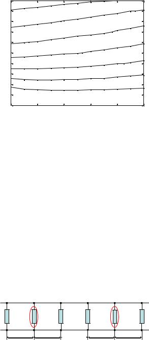
As a first step of the design, the equivalent circuit of Fig. 4 is optimized to meet the electrical requirements. The equivalent circuit includes normalized reactances, shunt connected between sections of equivalent line modelling TE10 propagation.
|
fz1 |
|
|
|
fz2 |
|
jx01 |
jx12 |
jx23 |
jx34 |
|
jx45 |
jx56 |
l1 |
l2 |
|
l3 |
l4 |
l5 |
|
Fig. 4. Filter quivalent circuit including either inductive or resonant reactances (marked by ellipses).
All coupling reactances are assumed to be frequency dependent as due to lumped inductances but x12 and x45, behaving as series lumped resonators with resonance fz1 and fz2 respectively. The position of resonant reactances is not critical, if I/O coupling ones are excluded, and other choices are thus possible.
As a result of the optimization procedure, the following values are obtained for the normalized reactances (all evaluated at f0 = 12 GHz) and the waveguide lengths respectively: x01 =
Selecting the double insert solution, so maintaining the symmetry into the whole mechanical structure, the required lengths of each inductive coupling structure can be evaluated from Fig. 6 and are listed in Table II.
To complete the design, the lengths of waveguide sections corresponding to resonators have to be determined. This can be done starting from lengths li (see Fig. 4), taking into account
the equivalent electrical lengths θeqi (see Fig. 2.b) of adjacent discontinuities, resulting into the edge-to-edge distances ci listed in Table III.
The overview of the designed metal-insert filter is shown in Fig. 7 and a full-wave optimization has been performed, starting from the dimensions listed in Tables I-III. Slightly adjusting the heights of the two resonant fins and the length of the five resonators only, the frequency response of Fig. 8 is obtained (thick lines). For the sake of comparison, the reference response of the optimized equivalent circuit of Fig. 4 is plotted in the same figure (thin lines).
Closer agreement can be achieved if the remaining filter dimensions are included into the optimization procedure. It is worthwhile to note that the overall length of the pseudo-elliptic filter is 93.2 mm, while the conventional metal-insert one, maintaining the same electrical requirements and employing a single insert, results to be 106.2 mm. So, in addition to a steeper roll-off, the designed filter is about 14 % shorter, maintaining the same level of losses.
TABLE I. |
DIMENSIONS OF RESONANT COUPLINGS (SINGLE OFFSETTED |
||
|
|
INSERT) |
|
|
|
|
|
|
|
x12 |
x45 |
fz (GHz) |
|
11.75 |
12.25 |
d (mm) |
|
2.727 |
3.238 |
h (mm) |
|
5.415 |
5.073 |

2018 IEEE MTT-S International Conference on Numerical Electromagnetic and Multiphysics Modeling and Optimization (NEMO)
TABLE II. |
|
DIMENSIONS OF INDUCTIVE COUPLINGS (DOUBLE INSERT) |
|||||||||||||||||
|
|
|
|
|
|
|
|
|
|
|
|
|
|
|
|
|
|
|
|
|
|
|
|
|
|
x01 |
|
|
|
x23 |
|
|
|
x34 |
|
x56 |
|||
d (mm) |
|
|
1.983 |
|
|
|
10.128 |
|
|
10.078 |
|
1.887 |
|||||||
|
TABLE III. |
WAVEGUIDE LENGTHS (EDGE-TO-EDGE DISTANCE) |
|||||||||||||||||
|
|
|
|
|
|
|
|
|
|
|
|
|
|
|
|
|
|
||
Res. # |
|
1 |
|
|
2 |
|
|
3 |
|
|
|
4 |
|
5 |
|||||
c (mm) |
|
12.774 |
|
12.669 |
11.947 |
|
13.031 |
12.668 |
|||||||||||
|
4 |
|
|
|
|
|
|
|
|
|
|
|
|
|
|
|
|
|
|
|
|
|
|
|
|
|
|
- |
|
3 |
|
|
|
|
|
||||
|
3.8 |
|
|
|
|
|
|
0 |
|
4 |
|
|
|
|
|
||||
|
|
|
|
|
|
|
1 |
|
9 |
|
|
|
|
|
|||||
|
|
|
|
|
|
|
|
. |
|
0 |
|
|
|
|
|
||||
|
|
|
|
|
|
|
|
1 |
|
|
|
|
|
|
|||||
|
|
|
|
|
|
|
|
4 |
|
1 |
|
|
|
|
|
||||
|
|
|
|
|
|
|
|
|
. |
|
|
|
|
|
|||||
|
|
|
|
|
|
|
|
1 |
|
0 |
|
|
|
|
|
||||
|
3.6 |
|
|
|
|
|
|
4 |
|
|
|
|
|
|
|
|
|
|
|
|
|
|
|
|
|
|
|
|
|
|
|
|
|
|
|
|
|
|
|
|
3.4 |
|
|
|
|
|
|
|
|
|
11.75 GHz |
|
|
|
|
|
|||
|
|
|
|
|
|
|
|
|
|
|
|
|
|
|
|
|
|
|
|
(mm) |
3.2 |
|
|
|
|
|
|
|
|
|
|
|
|
|
|
|
|
|
|
|
|
|
|
|
|
|
|
|
|
0 |
|
|
|
|
|
||||
|
|
|
|
|
|
|
|
- |
3 |
|
|
|
|
|
|||||
|
3 |
|
|
|
|
|
|
0 |
4 |
|
|
|
|
|
|||||
|
|
|
|
|
|
|
. |
9 |
|
|
|
|
|
||||||
|
|
|
|
|
|
|
|
1 |
|
|
|
|
|
|
|
|
|
||
d |
|
|
|
|
|
|
|
1 |
1 |
|
|
|
|
|
|||||
|
|
|
|
|
|
|
4 |
. |
|
|
|
|
|
||||||
|
2.8 |
|
|
|
|
|
|
1 |
0 |
|
|
|
|
|
|||||
|
|
|
|
|
|
|
4 |
|
|
|
|
|
|
|
|
|
|||
|
2.6 |
|
|
|
|
|
|
|
|
|
|
|
|
|
|
|
|
|
|
|
2.4 |
|
|
|
|
12.25 GHz |
|
|
|
|
|
|
|
|
|
||||
|
|
|
|
|
|
|
|
|
|
|
|
|
|
|
|||||
|
2.2 |
|
|
|
|
|
|
|
|
|
|
|
|
|
|
|
|
|
|
|
|
|
|
|
|
|
|
|
|
|
|
|
|
|
|
|
|
|
|
|
2 |
|
|
|
|
|
|
|
|
|
|
|
|
|
|
|
|
|
|
|
4.5 |
|
|
|
|
|
5 |
|
|
5.5 |
|
6 |
|||||||
h (mm)
Fig. 5. Design chart for offsetted single fins (s = a/4).
|
100 |
|
|
|
|
|
|
|
|
|
|
|
eq |
10-1 |
|
|
|
|
|
|
|
|
|
|
|
x |
|
|
|
|
|
|
|
|
|
|
|
|
|
10-2 |
2 |
3 |
4 |
5 |
6 |
7 |
8 |
9 |
10 |
11 |
12 |
|
1 |
|||||||||||
|
|
|
|
|
|
d [mm] |
|
|
|
|
|
|
Fig. 6. Normalized equivalent reactance xeq vs. length d for a double inductive post (s = a/4).
Fig. 7. Perspective view of the metal-insert filter.
|
0 |
|
|
|
|
|
|
|
|
|
|
|
-10 |
|
|
|
|
|
|
|
|
|
|
|
-20 |
|
|
|
|
|
|
|
|
|
|
(dB) |
-30 |
|
|
|
|
|
|
|
|
|
|
|
|
|
|
|
|
|
|
|
|
|
|
-Parameters |
-40 |
|
|
|
|
|
|
|
|
|
|
-50 |
|
|
|
|
|
|
|
|
|
|
|
S |
|
|
|
|
|
|
|
|
|
|
|
|
-60 |
|
|
|
|
|
|
|
|
|
|
|
-70 |
|
|
|
|
|
|
|
|
|
|
|
-80 |
11.2 |
11.4 |
11.6 |
11.8 |
12 |
12.2 |
12.4 |
12.6 |
12.8 |
13 |
|
11 |
||||||||||
|
|
|
|
|
Frequency (GHz) |
|
|
|
|
||
Fig. 8. Simulated full-wave (thick) and reference (thin line) frequency response of the metal-inser filter.
REFERENCES
[1]P. Kozakowski, and. A. Deleniev, “All metal insert E-plane filter with integrated extracted pole resonator,” Proc. 42th EuMC, Amsterdam (NL), Oct. 2012.
[2]E. Doumanis, G. Goussetis, and. J. Huurinainen, “Transmission zero realization in E-plane filters by means of I/O resonator tapping,” Proc. 46th EuMC, London (UK), Oct. 2016.
[3]N. Mohottige, O. Glubokov, U. Jankovic, and D. Budimir, “Ultra compact inline E-plane waveguide bandpass filters using cross coupling,” ,” IEEE Trans. MTT, vol. 64, no. 8, pp. 2561-2571, Aug. 2016.
[4]M. Politi, and A. Fossati, “Direct coupled waveguide filters with generalized Chebyshev response by resonating coupling structures,” Proc. 40th EuMC, Paris (F), Sept. 2010.
[5]G.G. Gentili, L. Accatino, and G. Bertin, “The generalized 2.5D finiteelement method for analysis of waveguide components,” IEEE Trans. MTT, vol. 64, no. 8, pp. 2392-2400, Aug. 2016.
[6]L. Codecasa, G.G. Gentili, and M. Politi, “Wideband analysis of lossless multimode waveguide junctions,” Proc. Nemo 2017, Sevilla (E), May 2017.