

диафрагмированные волноводные фильтры / 58a9b29f-8fe6-40e5-899c-b214307f576e
.pdfIEEE MICROWAVE AND WIRELESS COMPONENTS LETTERS, VOL. 21, NO. 4, APRIL 2011 |
209 |
In-Line Pure -Plane Waveguide Band-Stop
Filter With Wide Spurious-Free Response
José R. Montejo-Garai, Jorge A. Ruiz-Cruz, Jesús M. Rebollar, and Teresa Estrada
Abstract—A new compact pure -plane waveguide structure is proposed for coupling band-rejection cavities to the main rectangular waveguide in bandstop in-line filters. This coupling structure reduces drastically the unwanted resonances in filters with a very large pass band requirement. Moreover, it has some additional advantages. First, unlike typical inductive irises, large coupling coefficients can be implemented. Second, a pure -plane configuration is achieved, which simplifies the manufacturing and also reduces significantly the computational effort. Third, in the design, by means of distributed model circuits, the rejection cavities are individually designed and connected by phase shifters maintaining the -plane layout. Experimental validation is demonstrated by a pseudoelliptic fifth-order bandstop filter centered at 28 GHz and 2% fractional stop band. It is free of spurious resonances in the full Ka-band.
Index Terms—Bandstop filter, in-line filter, pseudoelliptic response, synthesis, transmission zero, waveguide filter.
I. INTRODUCTION
ANDSTOP filters are essential in those applications B where a specific narrow frequency band needs to be strongly attenuated. For example, they usually are connected to the output of high power non-linear amplifiers to reject the spurious harmonic frequencies [1].
The standard design technique is based on cascading a series of bandstop resonant elements disposed along a main transmission line. The separation between them is an odd multiple of a quarter-wavelength. In this approach, each resonator generates one attenuation pole at the center of the stop band of the filter, and maximally flat or equiripple band pass between rejected bands is achieved. However, if additional control about the position of the reflection zeros is required, solutions based on pseudoelliptic or elliptic responses must be considered [2]. In addition to the in-line configuration, the generalized cross-cou- pling network including the source-load coupling can be used [3].
A very interesting and practical in-line configuration is derived from the extracted pole technique. The sequential ex-
Manuscript received September 07, 2010; revised December 07, 2010; accepted January 04, 2011. Date of publication March 03, 2011; date of current version April 08, 2011. This work was supported by the Comisión Interministerial de Ciencia y Tecnología (CICYT) Spain, under project TEC2007-64556.
J. R. Montejo-Garai and J. M. Rebollar are with the Departamento de Electromagnetismo y Teoría de Circuitos, Universidad Politécnica de Madrid, Ciudad Universitaria s/n, Madrid 20840, Spain (e-mail: jr@etc.upm.es).
J. A. Ruiz-Cruz is with the Escuela Politécnica Superior, Universidad Autónoma de Madrid, Madrid 28409, Spain.
T. Estrada is with the Laboratorio Nacional de Fusión, Asociación EuratomCIEMAT, Madrid 28040, Spain.
Color versions of one or more of the figures in this paper are available online at http://ieeexplore.ieee.org.
Digital Object Identifier 10.1109/LMWC.2011.2105468
Fig. 1. Coupling structures between band-rejection cavities and the main rectangular waveguide: (a) classical inductive iris; (b) new proposed configuration to increase the coupling level and eliminate spurious resonances; and (c) manufacturing of the filter with the new cavities.
traction of phase-shifters and resonators allows generating both symmetric and asymmetric responses with absolute control of the transmission zeros (TZ) position [3], [4].
Nevertheless, besides the different synthesis methods, all of them give responses valid only over a narrow frequency range around the center frequency of the stop band. In most cases, poor results are forecasted for a spurious response, especially in the case of waveguide implementations.
An application of great interest that uses bandstop filters is the density profile measurement in magnetically confined fusion plasmas [5], [6]. The monitoring system requires, in addition to attenuate the signal at the frequency of the gyrotron, a very large frequency range without spurious response. This challenging specification forces to a different point of view to deal with the design, because after the circuit synthesis, full-wave simulation is imperative to predict, control, and finally eliminate the unwanted spikes and resonances. Following this analysis, the in-line configuration is a more suited alternative in comparison with cross-coupled networks to cope with the spurious resonance since every transmission zero is controlled independently.
In this work, a new compact  -plane waveguide structure for coupling the band-reject cavities to the main rectangular waveguide in in-line configuration is proposed. The typical coupling by inductive iris [1] working below cut-off frequency is replaced by a slot asymmetrically connected to the resonant cavity (Fig. 1). The advantage is twofold: on the one hand, high coupling coefficients can be implemented; on the other hand, there are not spurious resonances due to irises as it will be shown by experimental validation.
II. SYNTHESIS AND CIRCUIT MODEL
The synthesis of the filter is based on the approach proposed by Cameron [3], [4] using the extracted pole technique. In essence, the roles of 


 and
and 


 of the low-pass prototype are interchanged, i.e., the return loss response becomes the rejection response and conversely. Using a Chebyshev charac-
1531-1309/$26.00 © 2011 IEEE
210 |
IEEE MICROWAVE AND WIRELESS COMPONENTS LETTERS, VOL. 21, NO. 4, APRIL 2011 |
TABLE I
SPECIFICATIONS OF THE BANDSTOP FILTER
Fig. 2. |
Bandstop (5–1) filter network ( , reflection zero at ). |
|
Element values: |
, 81.152, 80.043, , , |
|
87.732, |
; |
, 1.7436, 2.4864, 2.3236, 0.95487; . |
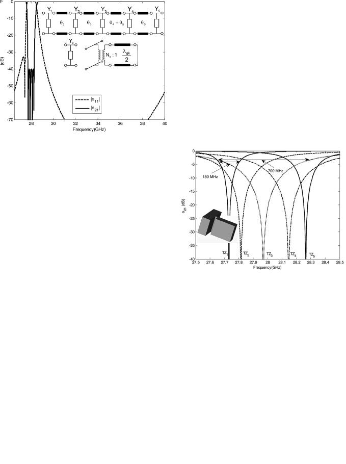
Fig. 3. Distributed circuit model of the bandstop filter; circuit response.
teristic, the equiripple stop-band attenuation can be specified unlike the low-pass to band-stop classic transformation.
In the synthesis process, for the Nth-degree bandstop filter,  transmission zeros are extracted at the former reflection zeros. Different orders in the sequence of extraction provide different circuit elements, although all of them yield the same response. Therefore, it is worth studying different sequences of extraction to find suitable values for the impedance level of the resonators and phase-shifters taking into account that the filter will be implemented in rectangular waveguide. After extracting all poles and their related phase lengths, the synthesis process ends with the extraction of a parallel inverter of unity value for the case of non-canonical configurations. An example will be shown now in order to fulfill with the specifications collected in Table I for a bandstop filter.
A fifth-order prototype satisfies the above specifications. Because the odd order of the filter, one of the reflection zeros is located at 

 and it will become a transmission zero in the center frequency. A singularity appears at this frequency point in the pole extraction procedure that can be avoided introducing a transmission zero in the low pass prototype to obtain an asymmetric response, moving the reflection zero from

 to a closer position. The form of the synthesized bandstop network (5-1) is shown in Fig. 2 with the corresponding element values.
Fig. 3 shows the response of the distributed circuit model that includes transmission lines incorporating the frequency dependence for the impedance and propagation constant in the WR28 waveguide. Phase-shifters 
 and
and 
 as well the two inverters of unity value are not considered.
 represents every of the five transmission zeros, and the ideal transformer
 its couplings to the main line. As can be observed there is no spurious response in the full Ka band. However, it must be considered that this model has not taken into account the different resonances of the rectangular waveguide cavities used to implement the transmission zeros and the interaction between high order modes. This will be considered now.
III. FULL WAVE DESIGN AND EXPERIMENTAL RESULTS
After the synthesis process, the full-wave design of the filter is carried out. In the present design, the main priority has been to achieve a very large frequency range in the response without
Fig. 4. Circuit response of the five transmission zeros considering every one independently, and layout of the new coupling and reaction cavity.
spurious. Consequently, a new compact  -plane waveguide structure for coupling the reaction cavities to the main waveguide has been investigated. Fig. 4 shows the response of the five transmission zeros considering everyone independently according to the distributed circuit. As can be observed the coupling level (3 dB bandwidth) is very different depending on the transmission zero; the lowest value corresponds to

 (180 MHz, 0.65% fractional bandwidth) and the largest value to

 (700 MHz, 2.5%).
In order to implement this large margin of coupling values, the classic inductive iris [1] connecting the cavities to the main body [Fig. 1(a)] is replaced by a slot asymmetrically connected to the cavity [Fig. 1(b)]. In this way, the electric field is coupled through the total width of the waveguide instead of a par- tial-width iris, leading to higher coupling values. At the same time, the spurious resonances usually introduced by the irises are eliminated. In addition to the previous two advantages, maintaining the same width (WR28, 


 ,
, 


 ) in the full structure simplifies the manufacturing and improves the efficiency of the mode matching full wave simulation (only


 modes are required in the resultant
  -plane structure and the simulation is extremely fast).

MONTEJO-GARAI et al.: IN-LINE PURE -PLANE WAVEGUIDE BAND-STOP FILTER |
211 |
Fig. 5. Full-wave simulation of the fifth-order bandstop fiter. The layout is |
Fig. 7. Experimental and simulated performances of the fifth order bandstop |
plotted with main dimensions (mm) to show the aspect ratio (WR28 ports). |
filter. |
Fig. 6. Full-wave simulation of the fifth-order bandstop filter, completely free of spurious resonances. The new layout including grooves in the cavities is plotted with main dimensions (mm) to show the aspect ratio (WR28 ports).
Fig. 4 shows the responses of the five transmission zeros using the distributed model used as the reference in a full-wave optimization process to obtain the geometric dimensions of the slot and the reaction cavity.
Once the five coupling structures have been designed, they are connected using as the initial values the phase shifters calculated in the synthesis procedure (see Fig. 2, 
 -
-
 ). Since these lengths must be as shorter as possible to reduce undesired spurious, the cavities are alternated between the upper and lower faces of the main waveguide. After an optimization process the final response and the structure is presented in Fig. 5. As can be observed, the stop band centered at 28 GHz has the specified level of 40 dB for attenuation.
Although the iris resonances have been already eliminated because of the new configuration, there is another stop band close to 38 GHz. This spurious band corresponds to the next resonant frequency of the rectangular cavity. One possibility to eliminate it would be to use tuning screws. However, the  -plane config-
uration can be preserved by introducing a groove in the middle of every cavity (see the inset of Fig. 6) to shift the higher-order resonances, while maintaining the transmission zeros. This is done with all the cavities to eliminate the spurious band. A new optimization is used to re-adjust the final filter lengths. Fig. 6 shows the final simulation without spurious resonances in the full Ka band along with the filter layout. Fig. 7 shows the comparison between the full wave simulation using the mode matching method and the measurements. As can be observed the agreement is excellent. The specifications detailed in Table I are fulfilled. Because of the brass, the maximum insertion losses are 0.4 dB.
IV. CONCLUSION
The proposed pure  -plane structure can be used for coupling band-rejection cavities in bandstop in-line filters with very stringent requirements of wide free-spurious response and ease of manufacturing. Besides its use in telecommunication front-ends (spatial or terrain systems), other possible application is in monitoring systems of fusion plasma, where the tested prototype is working ( CIEMAT , stellarator TJ-II). The experimental results have demonstrated an excellent performance, with a good agreement with the expected simulations which are straightforward for the proposed pure
  -plane structure.
REFERENCES
[1] G. Matthaei, L. Young, and E. M. T. Jones, Microwave Filters, Impedance Matching Networks and Coupling Structures, first ed. New York: McGraw-Hill, 1964, ch. 12, pp. 725–727.
[2]J. D. Rhodes, “Waveguide bandstop elliptic filters,” IEEE Trans. Microw. Theory Tech., vol. MTT-20, pp. 715–718, Nov. 1972.
[3]R. J. Cameron, “General prototype network synthesis methods for microwave filters,” ESA J., vol. 6, pp. 193–206, 1982.
[4]R. J. Cameron, C. M. Kudsia, and R. R. Mansour, Microwave Filters for Communications Systems, first ed. New York: Wiley, 2007, ch. 10, pp. 364–366.
[5]T. Estrada, J. Sánchez, B. van Milligen, L. Cupido, A. Silva, M. E. Manso, and V. Zhuravlev, “Density profile measurements by AM reflectometry in TJ-II,” Plasma Phys. Controlled Fusion, vol. 43, pp. 1535–1545, 2001.
[6]T. Happel, T. Estrada, E. Blanco, V. Tribaldos, A. Cappa, and A. Bustos, “Doppler reflectometer system in the stellarator TJ-II,” Rev. Sci. Instrum., vol. 80, no. 073502, pp. 1–8, 2009.