

диафрагмированные волноводные фильтры / e6f97bf3-abce-4e0b-8eea-9ade290ffe1a
.pdfCompact Dielectric-filled Waveguide
Filters and Diplexers
N. Mohottige, D. Budimir
Wireless Communications Research Group,
School of Electronics and Computer Science, University
of Westminster London, W1W 6UW, UK
d.budimir@wmin.ac.uk
Abstract— This paper presents electromagnetic simulations of dielectric-filled rectangular waveguide bandpass filter structures with microstrip to waveguide transitions as well as a diplexer based on such filters for modern wireless systems. The two bandpass filters have been designed and simulated at centre frequencies of 11.85 and 14.25 GHz, respectively. A significant size reduction is achieved through dielectric filling.
I.INTRODUCTION
Over the past few decades rectangular waveguide filters have been a sustainable solution for low-cost, low-loss and high power filters for modern microwave and millimeter-wave applications [1]-[3]. However current advancements in mobile communication systems have placed new challenges for compact millimeter wave waveguide filters and diplexers. Commonly, diplexers are used for separation of received and transmit signals served by a common antenna. Initial step in designing diplexers are to first design and simulate the individual filters satisfying the specifications required. Secondly, these filters are combined together using suitable matching network. Most commonly used being T-junctions.
Dielectric materials have been used extensively in RF and Microwave components, especially in resonators and filters. Dielectric filled waveguide cavities have been previously proposed in [4], and have shown that a size reduction by factor
of 1/ can be achieved. This paper proposes two compact dielectric filled rectangular E-plane filters and a diplexer based on such filters. These structures, while improving compactness, maintain the low-cost and mass-producible characteristics of conventional E-plane technology. As the structure is reduced considerably in size it becomes difficult to use conventional waveguide flanges as these will also need to be reduced in size and this become impractical due to fabrication difficulties. Therefore integrated Microstrip to Waveguide transitions similar to that in Substrate Integrated Waveguides was adopted to facilitate measurement of these structures.
II.PROPOSED FILTER AND DIPLEXER STRUCTURES
The proposed dielectric-filled rectangular waveguide bandpass filter structures with Microstrip to Waveguide transitions are shown in Figure 1. The filter structure is filled with dielectric material which has relative dielectric permittivity of 3.38, and the metal inserts have a thickness of 0.1 mm. The metal septas are inserted in the line of symmetry of hollow dielectric-filled rectangular waveguide of width ‘a’
Z. Golubicić
TTI Technologías de Telecomunicaciones y de la Informacíon Norte
PCTCAN c. Albert Einstewin 14 39011, Santander, Spain.
and height ‘b’. As the waves within the filter now propagate in a dielectric medium, the wavelength is reduced by the square root of the permittivity. The electromagnetic analysis, of the proposed waveguide filter structures, is based on the finite element method (CSTTM) [5]. The following design examples are considered. Filter 1 is a dielectric-filled rectangular waveguide bandapss filter which is required to operate and provide 30 dB attenuation at 15 GHz, while a good match/return loss > 15 dB from 14 to 14.5 GHz, where as Filter 2 should provide a pass band return loss >15 dB from 10.95 to 12.75 GHz with attenuation > 35 dB at 14 GHz.
Figure 1. Configuration of dielectric-filled waveguide bandpass filter
Figure 2. Configuration of dielectric-filled waveguide diplexer
III.RESULTS
Configuration of the dielectric filled waveguide filter with the transitions is shown in Figure 1. The transitions are built on the same substrate as that in the waveguide filters. Therefore 0.5mm thick section of the waveguide substrate is extended to support the Microstrip transitions. The width of transmission line for 50Ω impedance with substrate height of 0.5mm, metallization thickness of 0.02mm and permittivity of 3.38 is
978-1-4673-0462-7/12/$31.00 ©2012 IEEE
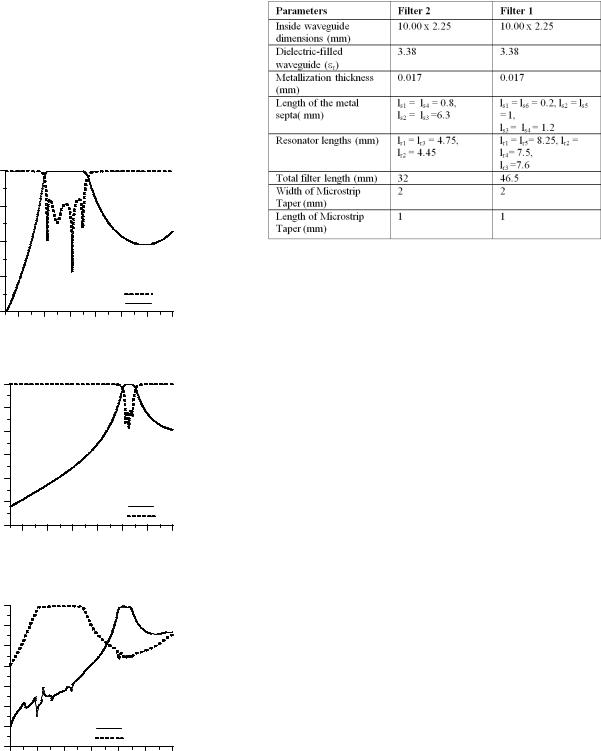
calculated to be 1.14mm. The matching from 50Ω line to the waveguide section is achieved by the tapper section which converts quasi-TEM mode propagating in Microstrip line to the TE10 mode of the waveguide. Ridged waveguide sections are used to achieve matching at all three ports [6]. The diplexer is designed such that it generates an open circuit at Filter 2 at the pass band of Filter 1 and vice versa. The layout of the diplexer configuration is shown in Figure 2. Figure 3 and 4 shows the simulated S-parameter response of Filter 1 and Filter 2 respectively. Figure 5 shows the corresponding S-Parameter response of the dielectric filled waveguide diplexer. Dimensions of both structures are presented in Table 1.
|
0 |
|
|
|
|
|
|
(dB) |
-20 |
|
|
|
|
|
|
|
|
|
|
|
|
|
|
S-Parameters |
-40 |
|
|
|
|
|
|
-60 |
|
|
|
|
|
|
|
|
|
|
|
|
|
|
S 11 |
|
-80 |
|
|
|
|
|
S 21 |
|
|
|
|
|
|
|
|
|
10 |
11 |
12 |
13 |
14 |
15 |
16 |
Frequency (G Hz)
Figure 3. Simulated S parameters of the proposed filter1
|
0 |
|
|
|
|
|
|
(dB) |
-20 |
|
|
|
|
|
|
-40 |
|
|
|
|
|
|
|
S-Parameters |
|
|
|
|
|
|
|
-60 |
|
|
|
|
|
|
|
-80 |
|
|
|
|
|
|
|
|
|
|
|
|
|
|
|
|
-100 |
|
|
|
|
|
S21 |
|
|
|
|
|
|
|
|
|
-120 |
|
|
|
|
|
S11 |
|
|
|
|
|
|
|
|
|
10 |
11 |
12 |
13 |
14 |
15 |
16 |
Frequency (GHZ)
Figure 4. Simulated S parameters of the proposed filter 2
|
0 |
|
|
|
|
|
|
|
-20 |
|
|
|
|
|
|
(dB) |
-40 |
|
|
|
|
|
|
|
|
|
|
|
|
|
|
-Parameters |
-60 |
|
|
|
|
|
|
-80 |
|
|
|
|
|
|
|
-100 |
|
|
|
|
|
|
|
S |
|
|
|
|
|
|
|
|
-120 |
|
|
|
|
S21 Filter 2 |
|
|
-140 |
|
|
|
|
S21 Filter 1 |
|
|
|
|
|
|
|
|
|
|
10 |
11 |
12 |
13 |
14 |
15 |
16 |
Frequency (GH z)
TABLE I
DIMENSIONS OF PROPOSED WAVEGUIDE FILTERS WITH
TRANSITIONS
IV. CONCLUSION
Two dielectric filled rectangular waveguide bandpass filter structures with integrated microstrip to waveguide transitions have been presented. A diplexer based on such filters was also designed and simulated. In a practical point of view, these structures can be realized through utilization of metallo dielectric insert within standard dielectric filled rectangular waveguides. The filter structures are designed and simulated at centre frequency 11.85 and 14.25 GHz. The proposed structures maintain low-cost and mass producible characteristics of E-plane waveguide filters while achieving significant size reduction.
REFERENCES
[1]Vicente E. Boria and Benito Gimeno, “Waveguide Filters for Satellites” IEEE Microwave Magazine, Vol.8, Issue 5, pp.60-70, October 2007.
[2]I. C. Hunter, Laurent Billonet, Bernard Jarry, Pierre Guillon, “Microwave Filters—Applications and Technology” IEEE Trans. Microwave Theory Tech.,Vol.50, pp. 794-805, Mar. 2002.
[3]D. Budimir, "Generalized Filter Design by Computer Optimization", ISBN 0-89006-579-9, Atrtech House Books, 1998.
[4]Y. Konishi, "Novel dielectric waveguide componentsmicrowave applications of new ceramic materials," Proceedings of the IEEE , vol.79, no.6, pp.726-740, Jun 1991.
[5]Microwave Studio, CST, 201
[6]A. Shelkovnikov, G. Goussetis, and D. Budimir, " Compact Ridged Waveguide Bandpass Filters and Diplexers”, Microwave and Optical Technology Letters, June 2004.
Figure 5. Simulated S parameter response of diplexer