

диафрагмированные волноводные фильтры / df4e093d-d55a-4c6c-8ad4-88e2ac45917e
.pdfFigure 4 Measured and simulated co-polarized radiation patterns at the frequency of 1.75 GHz ( : measured result, : simulated result):
(a) x–y plane; (b) z–x plane; (c) z–y plane
of 0.9 GHz are 1.35 and 1.37 dBi, respectively. The simulated and measured gains at the frequency of 1.75 GHz are 3.71 and 3.84 dBi, respectively. The proposed antenna has relatively high gains, while the thickness of the antenna element is decreased.
4. CONCLUSION
A newly compact and cable-fed patch antenna with dual-band performance has been proposed and implemented. By using a modified ground plane, a monopole radiator, and parasitic patches, the proposed small antenna can cover the GSM and DCS bands. In addition, the antenna has sufficiently high gain to be applied effectively in practical handset-antenna applications.
ACKNOWLEDGMENT
This work was supported by the National Research Laboratory (NRL) of the Ministry of Science and Technology, Korea, under contract no. M1-0203-00-0015.
REFERENCES
1.M. Yang and Y. Chen, A novel U-shaped planar microstrip antenna for dual-frequency mobile telephone communications, IEEE Trans Antennas Propagat 49 (2001), 1002–1004.
2.C.W. Chiu and F.L. Lin, Compact dual-band PIFA with multi-resona- tors, Electron Lett 38 (2002), 538 –540.
3.Z.D. Liu, P.S. Hall, and D. Wake, Dual-frequency planar inverted-F antenna, IEEE Trans Antennas Propagat 45 (1997), 1451–1458.
© 2005 Wiley Periodicals, Inc.
WAVEGUIDE BANDPASS FILTERS FOR MMIC APPLICATIONS
L. Lalehparvar and Djuradj Budimir
Wireless Communications Research Group
Department of Electronic Systems
University of Westminster
London W1W 6UW, U.K.
Received 10 March 2005
ABSTRACT: Novel 3D multilayer waveguide structures for MMIC filter applications are proposed and examined in this paper. Periodic multilayer-waveguide resonant structures, which can be used for bandpass filters, are presented. The structure has a high Q and supports a simple fabrication process. An MMIC filter based on this proposed periodic-resonator configuration is designed at 74 GHz using the commercial software package HFSS. The simulated S-pa- rameter responses and a photomicrograph of the fabricated monolithic dielectric filled rectangular waveguide on GaAs substrate are presented. © 2005 Wiley Periodicals, Inc. Microwave Opt Technol Lett 46: 471– 473, 2005; Published online in Wiley InterScience (www. interscience.wiley.com). DOI 10.1002/mop.21020
Key words: multilayer MMIC structures; waveguides; resonators; bandpass filter
1. INTRODUCTION
The steadily growth of commercial interest in millimiter-wave and submillimiter wave applications, especially in wireless communications, security and sensory applications, and military and transport electronics, has provided a significant challenge to conventional microwave circuits and their design methodologies. Highperformance narrowband bandpass filters exhibiting low insertion loss, compact physical size, and low fabrication cost are important
MICROWAVE AND OPTICAL TECHNOLOGY LETTERS / Vol. 46, No. 5, September 5 2005 |
471 |
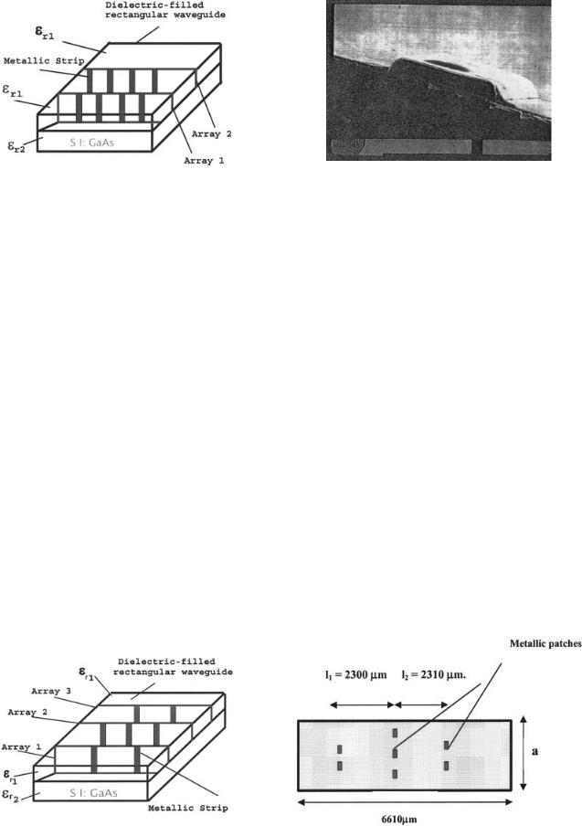
Figure 1 Cross section of proposed MMIC periodic-waveguide resonator structure
components to many microwave systems. Compact low-cost waveguide filters with high selectivity are therefore receiving particular interest [1, 2]. Multilayer techniques are now well established and are being used extensively in MMICs, since passive components such as filters still suffer from large size when applied to MMICs. This allows a higher packing density for microwave circuits resulting in reduced size circuits, which are of great importance at these high frequencies. Resonators are fundamental filter elements that determine to a large extent the filter’s electrical and physical properties. This paper presents a novel waveguide filter, based on a new proposed periodic-resonator structure. A resonator is designed, using the proposed topology, such that two arrayes of four metallic strips are used. An MMIC bandpass filter is also designed using this configuration. The filter consists of two resonator sections, whose lengths are chosen to be half the wavelength of the guide ( g/ 2) at resonant frequency. The substrate is 1000- m wide and has a height of 430 m. The MMIC bandpass filter is designed and simulated using the commercial FEM software package HFSS™.
2. CONFIGURATION
The proposed resonant structure is shown in Figure 1. The structure consists of a block of dielectric, which is transversely inserted inside a rectangular waveguide housing with a 1696 m and b 127 m. Poly is used as a dielectric material with r 3.6. The periodic metallization strips are supported by the dielectric block. Finally, the whole structure is placed on top of GaAs substrate. The first and last sections consist of two metal strips, while the middle section has three strips. The number and size of the metallic strips in the first and last array mainly determine the
Figure 3 Photomicrograph of a fabricated monolithic dielectric-filled rectangular waveguide on GaAs substrate
insertion loss and bandwidth of the filter. The proposed configuration still remains simple and further miniaturization of the proposed structure can be achieved upon use of high-permittivity, low-loss dielectric material. A cross section of the MMIC band- pass-filter structure, which is based on the proposed novel resonator structure, is shown in Figure 2. A photograph of the dielectricfilled rectangular waveguide on GaAs substrate is presented in Figure 3.
3. SIMULATED RESULTS
Since resonators are basic filter elements, the proposed periodic structure is used in filter applications (see Fig. 2), where an MMIC bandpass filter at 74 GHz is designed and simulated. The dimensions of the waveguide discontinuities are initially determined using the standard filter-design techniques found in [6].
Although full-wave electromagnetic simulations are necessary after the initial design, filter-design techniques assume idealized conditions. Figure 4 shows the structure and dimensions of the bandpass filter. The metallic strips, which make up the discontinuities, all have a 40- m width and a 127- m height. Their lengths are 10 m in the first and last array and 13 m in the middle array. The two resonator sections have lengths l1 2300m and l2 2310 m. The simulated S-parameters, S21 and S11, of the MMIC dielectric-filled waveguide filter are shown in Figure 5. All the responses in this paper were produced using the commercial software package HFSS™ [8].
Figure 2 Configuration of MMIC filter based on the proposed periodic |
|
dielectric-filled waveguide resonator structure |
Figure 4 Top view of the filter structure |
472 MICROWAVE AND OPTICAL TECHNOLOGY LETTERS / Vol. 46, No. 5, September 5 2005

Figure 5 Simulated S-parameter responses of the dielectric-filled waveguide filter
4. CONCLUSION
In this paper, a reduced-size novel periodic-waveguide resonant structure has been presented. It consists of a dielectric block that is transversely placed inside a rectangular waveguide formed in an MMIC substrate. The dielectric block supports periodic metallization patches. A bandpass filter at 74 GHz was designed and simulated and the simulated results were presented in order to verify the performance of the novel structure. This proposed configuration, results in the development of high-Q components, which are of great importance in filter applications at mm-wave frequencies.
REFERENCES
1.C. Kyriazidou, H. Contopanagos, and N. Alexopoulos, Monolithic waveguide filters using printed photonic-bandgap materials, IEEE Trans Microwave Theory Tech MTT-49 (2001), 297–307.
2.H. Contopanagos, N. Alexopoulos, and E. Yabolnovitch, High-Q rectangular cavities and waveguide filters using periodic metalo-dielectric slabs, IEEE Microwave Theory Tech Symp Dig, Baltimore, MD (1998), 1539 –1542.
3.R. Pous and D. Pozar, A frequency-selective surface using aperturecoupled microstrip patches, IEEE Trans Microwave Theory Tech MTT-33 (1991), 1763–1769.
4.D. Budimir and C. Turner, Novel high-Q waveguide E-plane resonators using periodic metallic septa, Microwave Opt Technol Lett 23 (1999), 311–312.
5.W. Yu, S. Dey, and R. Mittra, On the modeling of periodic structures using finite-difference time-domain algorithm, Microwave Opt Technol Lett 24 (2000), 151–155.
6.D. Budimir, Generalized filter design by computer optimization, Artech House, Boston, 1998.
7.N. Kinayman, N. Jain, and A. Buckle, Novel surface-mountable milli- meter-wave bandpass filter, IEE Microwave Wireless Compon Lett 12 (2002).
8.Ansoft HFSS ver. 8.5, Ansoft Technologies, 2002.
© 2005 Wiley Periodicals, Inc.
RESONANT FREQUENCIES OF A COMBINATION OF SPLIT RINGS: EXPERIMENTAL, ANALYTICAL AND NUMERICAL STUDY
A. Radkovskaya,1 M. Shamonin,2 C. J. Stevens,3 G. Faulkner,3 D. J. Edwards,3 E. Shamonina,4 and L. Solymar5
1 Magnetism Division Faculty of Physics
M. V. Lomonosov Moscow State University Leninskie Gory
Moscow 119992, Russia
2 Department of Electrical Engineering and Information Technology University of Applied Sciences
D-93025 Regensburg, Germany
3 Department of Engineering Science University of Oxford
Parks Road
OX1 3PJ Oxford, United Kingdom 4 Department of Physics University of Osnabru¨ ck
D-49069 Osnabru¨ ck, Germany
5 Department of Electrical and Electronic Engineering Imperial College of Science
Technology and Medicine Exhibition Road
London SW7 2BT, United Kingdom
Received 4 March 2005
ABSTRACT: The resonant frequencies of five different ring resonators are measured with the aid of a network analyser within the frequency range of about 1.5 to 2.8 GHz. The resonant frequencies for those configurations are also determined from numerical calculations using the commercially available MICRO-STRIPES package. The experimental and numerical results are shown to be very close to each other. Analytical results from various authors, available for three of the configurations, are also compared with the experimental results; one of them leads to a large discrepancy, but the other analytical approximations are shown to be not too far off. © 2005 Wiley Periodicals, Inc. Microwave Opt Technol Lett 46: 473– 476, 2005; Published online in Wiley InterScience (www.interscience.wiley.com). DOI 10.1002/mop. 21021
Key words: metamaterials; split-ring resonators; negative permeability; negative permittivity; negative refraction
1. INTRODUCTION
In order to produce the negative refractive index proposed by Veselago [1], it is necessary to find materials which possess both negative permittivity and negative permeability. Various methods for realising negative permittivity have been known for a long time. The aim at the time was to simulate plasma effects [see, for example, [2]). The possibility of obtaining negative permeability was first reported half a century ago [3], followed by further discussions [4, 5], but it was only fairly recently that a solution was offered in the form of split-ring resonators [6]. Rings (or rather cylinders) split in various ways were used well before that as resonators in nuclear magnetic resonance experiments, and were known as slotted-tube resonators [7], split-ring resonators [8], or loop-gap resonators [9]. Resonant structures based on split rings [10] were also proposed with the aim of acting as magnetic absorbers. The main consideration in the design of all these elements is that the wavelength must be much larger than the size of the element. Ideally, one would like to have an analytical formula that relates the resonant frequency to the parameters of the element. Simple analytic expressions based on heuristic arguments are available [8, 11, 12], there is also an analytic formulation [13,
MICROWAVE AND OPTICAL TECHNOLOGY LETTERS / Vol. 46, No. 5, September 5 2005 |
473 |