

диафрагмированные волноводные фильтры / de89094c-619f-4a56-802d-62e06997dacc
.pdfCompact Waveguide Bandpass Filters with Enhanced Stopband Performance
Niranchanan Suntheralingam and D. Budimir
Wireless Communications Research Group, Department of Electronic Communication and Software Engineering, University of Westminster, 115 New Cavendish Street, London, W1W 6UW, United Kingdom
d.budimir@westminster.ac.uk
Introduction
In recent years there has been a strong interest worldwide in developing advanced periodic structures for microwave, mm-wave and optical applications. Waveguide structures have been used for decades as a convenient medium for propagation of electromagnetic waves, realized in different waveguide configurations. Periodic structures of various types have been gained interest in the microwave and millimeter-wave regime due to various interesting properties common to all periodic structures [1]-[3]. The S-shaped resonator structures can be used to alter electromagnetic properties of metal surfaces to perform variety of functions [4, 5]. The passband - stopband characteristics of such periodic structures and the support of slow wave propagation [6] refer to the existence of frequency bands throughout which a wave propagates along the structure unattenuated (except for thermal losses) which is separated by frequency bands throughout which the wave is cut off and does not propagate. The passbandstopband property is therefore of interest for its frequency filtering aspects. Furthermore in filter applications, periodic structures when introduced in the resonators of bandpass filters have been reported to offer reduced physical size and improved filtering performance. This is due to the slow-wave effect; the phase velocity and the guided wavelength of the slow wave are significantly reduced relative to those of a wave propagating in a comparable homogeneous line. Hence the length of a half wavelength resonator is accordingly reduced. Also due to the dispersion relation of slow waves, improved selectivity and enhanced stopband performance can be achieved.
This paper therefore proposes for replacement of the conventional section of rectangular waveguide E-plane filter with the S-shaped resonator loaded waveguide structure, consist of a periodic cascade of metal septa. These structures while improving the stopband performance and compactness, maintain the low-cost and mass-producible characteristics of split-block E-plane technology.
Proposed Filter Structure
The proposed S-shaped resonator loaded waveguide filter structure is constructed with the transmission line loaded metal-dielectric slab, which conveniently facilitates the S-shaped resonators with the metal septa. The proposed structure and the dimensions of the etched S-shaped resonator are illustrated in Figure 1. The S-shaped resonators are presented on a single side of the dielectric block and is characterised by the following parameters. The dielectric used is Rogers RT/Duroid 5880 (relative dielectric permittivity of 2.2) with its height of 0.508 mm and the metallisation thickness of 0.0017 mm. Standard rectangular waveguide of WG-16 (a = 22.86 mm, b = 10.16 mm) has been used as the housing to fit the dielectric slab.
978-1-4244-2642-3/08/$25.00 ©2008 IEEE
Simulation and Experimental Results
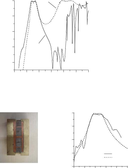
The electromagnetic analysis of the conventional E-plane waveguide filter structure is based on the mode matching method [7]. Mode matching with 40 modes has been used for the simulation of the conventional E-plane waveguide filter case while finite element method (HFSSTM) [8] for the proposed S-shaped filter. In order to derive a design procedure for the propsed type filter, the propagation characteristics of the slow wave, such as the guided wavelength or phase velocity, need to be determined. These in turn are determined by geometrical parameters, namely the gaps and the lengths. The gaps can be chosen arbitrarily. The periodicity lengths, together with the chosen gaps will effectively determine the wavelength; this in turn should determine the length lres. The simulated insertion losses for a conventional rectangular waveguide filter at 9.45 GHz and the proposed S-shaped resonator loaded filter at the same frequency are shown in Figure 2., From the Figure 2. it is evident that the enhancement in stopband performance is clearly obtained by employing the S-shaped resonators. Dimensions of the conventional and the proposed filter are given in Table I. Fabrication has been done in our lab using standard PCB process and the response was measured with the Agilent PNA (E8361A) vector network analyzer. Fabricated prototype of this proposed filter and its simulated and measured insertion losses are shown in Figure 3. The measured response demonstrates a very good agreement with the simulation.
Table I
DIMENSIONS OF THE CONVENTIONAL AND THE PROPOSED S-SHAPED RESONATOR LOADED WAVEGUIDE FILTERS AT
9.45 GHZ
Parameters (mm) |
Conventional |
S-shaped resonator |
|
WG filter |
loaded WG filter |
|
|
|
WG inner dimensions (WG16) |
22.86*10.16 |
22.86* 10.16 |
|
|
|
Total structure length (l) |
112.5 |
51 |
|
|
|
Dielectric slab length |
- |
51 |
|
|
|
Dielectric thickness |
- |
0.51 |
|
|
|
Metal septa length |
1.2, 3, 1.2 |
1.2, 3, 1.2 |
|
|
|
lres |
17.8 |
14 |
|
|
|
Metallization thickness |
0.1 |
0.0017 |
|
|
|
Conclusion
A novel type of E-plane S-shaped resonator loaded waveguide bandpass filter structure with enhanced stopband performance has been proposed. The structure has been easily realized with a single metalo-dielectric insert within the standard rectangular waveguide. The proposed structure maintains low-cost and mass producible characteristics while achieving significant size reduction. This kind of filters can be found applications particularly in the mmwave, submm-wave and terahertz range circuits, e.g. in low phase noise oscillators and highly selective filters, diplexers and multiplexers, frequency selective surfaces and antennas.

References
[1]Ian C. Hunter, Laurent Billonet, Bernard Jarry, Pierre Guillon, “Microwave Filters - Applications and Technology” IEEE Trans. Microwave Theory Tech.,Vol.50, pp. 794805, Mar. 2002
[2]D. Budimir, "Generalized Filter Design by Computer Optimization", ISBN 0-89006-579- 9, Atrtech House Books, 1998
[3]D. Budimir, “Optimized E-plane bandpass filters with improved stopband performance,”
IEEE Trans. Microwave Theory Tech., vol. 45, pp.212–220, Feb. 1997
[4] Jingjing Zhang , Hongsheng Chen , Yu Luo , Linfang Shen , Lixin Ran , Jin Au Kong , “Wideband backward coupling based on anisotropic left-handed metamaterial” , Applied Physics Letters , Vol. 90 , No. 4 , pp. 043506 , January 2007
[5] Hongsheng Chen , Lixin Ran , Jiangtao Huangfu , Xianmin Zhang , Kangsheng Chen , Tomasz Grzegorczyk , Jin Au Kong, “Left-handed Material Composed of Only S-shaped Resonators” , Physical Review E , Vol. 70 , No. 5 , pp. 1-4 , November 2004
[6]M. Morelli, I. Hunter, R. Parry, and V. Postoyalko, “Stop-band improvement of rectangular waveguide filters using different width resonators: Selection of resonator widths,” in IEEE MTT-S Int. Microwave Symp. Dig., Phoenix, AZ, May 2001, pp. 1623– 1626
[7]D. Budimir, "EPFIL-Waveguide E-plane Filter Design", Software and User Manual, ISBN 1-58053-083-4, Artech House Books, 1999
[8]Ansoft HFSS, Ansoft Technologies, 2005
l
b |
b
a |
lres |
h = 3.5mm
l2 = 1 mm
l1 = 0.5mm
w = 1.5 mm
Figure 1. Configuration of the proposed S-shaped resonator loaded bandpass filter
|
0.00 |
|
Conventional |
|
|
|
|
|
|
filter |
|
|
|
|
|
|
|
|
|
|
|
|
|
|
-10.00 |
|
|
|
|
|
|
B ) |
-20.00 |
|
|
|
|
|
|
S 21(d |
|
|
|
|
|
|
|
|
-30.00 |
|
S-shaped |
|
|
|
|
|
|
|
res. filter |
|
|
|
|
|
-40.00 |
|
|
|
|
|
|
|
6.00 |
8.00 |
10.00 |
12.00 |
14.00 |
16.00 |
18.00 |
|
|
|
Frequency(GHz) |
|
|
||
Figure 2. Simulated insertion losses of the conventional and the proposed bandpass filter
|
0 |
|
|
|
|
|
Loss (dB) |
-10 |
|
|
|
|
|
-20 |
|
|
|
|
|
|
Insertion |
|
|
|
|
|
|
-30 |
|
|
|
Measured |
|
|
|
|
|
|
|
Simulated |
|
|
-40 |
|
|
|
|
|
|
7 |
8 |
9 |
10 |
11 |
12 |
Frequency (GHz)
Figure 3. Fabricated prototype and the simulated and measured insertion losses of the S-shaped resonator loaded waveguide filter