

диафрагмированные волноводные фильтры / b290d40d-89c2-49cb-aa79-9df8bb51d58c
.pdfA E-Band E-Plane Type Waveguide Bandpass Filter
Deng Fang1,2, Bo Zhang1,2, Senior Member. IEEE, Jie He1
1. EHF Key Laboratory of Fundamental Science University of Electronic Science and Technology of China
Chengdu, Sichuan 611731, China Email: fangdeng608@126.com
2. National Key Laboratory of Application Specific Integrated Circuits, Hebei Semiconductor Research Institute
Shijiazhuang 050000, China
Abstract—this paper present the design of E-band E-plane bandpass waveguide filter with the E-plane inserted metal strip. And the waveguide filter is analyzed and optimized by electromagnetic simulation software according to the waveguide filter structure character. In simulation, the E band waveguide filter is operated from 72.2GHz to 73.8GHz with the maximum insertion loss of 0.41dB. And the relative bandwidth of the waveguide filter is about 2%. At last, contrast about the experiment results and the simulation data is analyzed.
Keywords—metal strip; waveguide filter; millimeter wave;
I. INTRODUCTION
With a rapid development of space exploration as well as environmental monitoring, imaging and communication, millimeter wave system has made great progress. Bandpass Filter plays an important role in communication systems, so it becomes increasingly important. To meet the requirement of modern communication systems, the better performance of millimeter wave Bandpass Filter is demanded, such as low cost, low insertion loss, high rejection etc. Millimeter wave filters with low insertion loss in passband and good stopband suppression is essential and important in millimeter wave radar and communication system. Millimeter filter could be divided into microstrip filter and waveguide filter. Millimeter wave microstrip filter has smaller structure and wider operation band than waveguide filter, but larger insertion loss and poor stopband suppression limit its application especially in higher millimeter wave frequency. Waveguide filter could achieve very low insertion loss at operation frequency band. At present waveguide filter is the main filter circuit structure in millimeter
978-1-5090-2276-2/16/$31.00 ©2016 IEEE
wave engineering application and system due to its excellent and stable performance[1][2].
II. THE CIRCUIT STRUCTURE OF FILTER
Fig. 1. The circuit structure of E-plane waveguide filter
The waveguide filter is consist of the waveguide cavity and the a inserted metal sheet in the middle of a waveguide broadside parallel to the E-plane as shown in Fig.1[3][4].Since the metal strip is separated by several certain length of hollow waveguide, it divide the waveguide into some adjacent equivalent resonant cavities[5]. The whole filter can be regarded as the alternating cascade of the waveguide with E –plane metal diaphragm and the hollow waveguide. Among them, the diaphragm has a coupling effect, and the adjacent diaphragm forms a resonant cavity. Normally, a half wavelength resonator is realized to design the filter. The length of the diaphragm plays a decisive role in the insertion loss, and the adjacent sheet forms a resonant cavity. Its length determines the center frequency. The performance of filter is decided by the synthetic
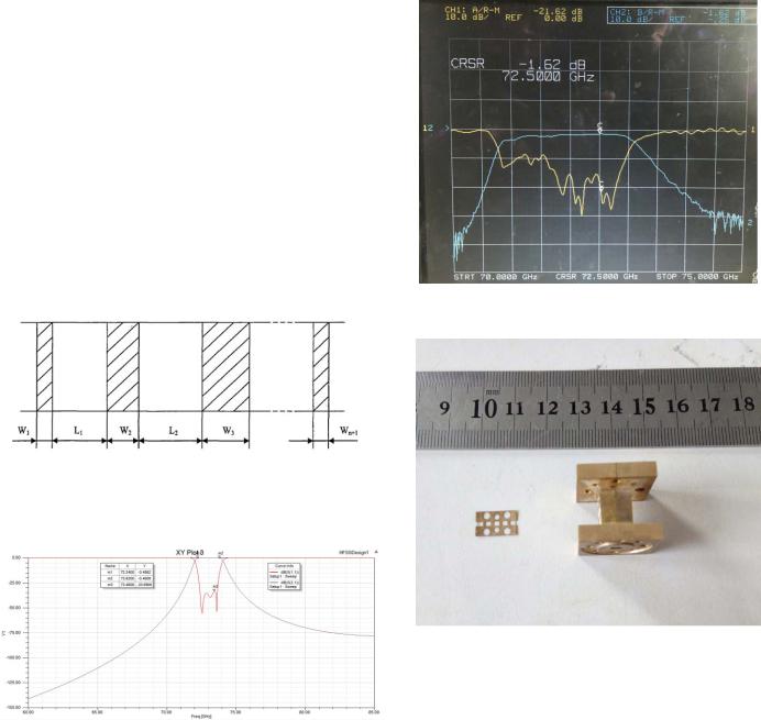
resonant effects of these adjacent resonant cavities through optimizing the structure dimension of inserted metal strip[6].
III.SIMULATION AND MEASUREMENTS
In order to achieve a compromise between performance and structure size, a five stage bandpass filter which has Chebyshev characteristic is designed [7]. The operation center frequency of waveguide filter is 73.0GHz, and 0.5dB passband is 1.6GHz. The width of inserted mental strip is 0.1mm, and the waveguide is standard WR12, which is 3.099mm × 1.549mm. According to the optimization of 3D electromagnetic simulation software. The structure of inserted metal strip is show in Fig.2, and the optimized design parameters are listed: W1=W6=0.2mm, W2=W5=1.195mm, W3=W4=1.515mm, L1=L5=2.055mm, L2=L4=2.08mm, L3=2.08mm.
The transmission and reflection characteristics are show in Fig.4.
Fig.4 The measured result of waveguide filter
Fig.2 The inserted metal strip and its parameters
And the optimized simulation result is shown in Fig.3.
Fig.3 The simulation result of waveguide filter
The simulation shows that 0.5dB passband of the filter is 1.6GHz (72.2GHz-73.8GHz) and the lower rejection is larger than 40dB if the frequency is lower than 71GHz, and the upper rejection is larger than 40dB in the range of 76-85GHz.
Based on the optimized structure parameters of inserted strip, the E band waveguide filter is fabricated and assembled.
Fig.5 The actual picture of the waveguide filter
And comparing the simulation result with experiment result, some useful results are obtained. In the experiment the lowest inserted loss 1.62dB and the passband is about 1.8GHz with 40dB rejection at the lower stopband. The center frequency is 71.9GHz, which means a 1.1GHz of frequency shift. The insertion loss of measured characteristics become worse due to lack of gold plating in the metal sheet. Lower inserted loss could be obtained by using high conductive strip, such as silver strip, and more precision waveguide cavity structure of the filter. The actual picture of the E band E-plane waveguide filter
is shown in Fig.5.
IV. CONCLUSION
The design of E band E-plane wideband waveguide bandpass filter is presented. More accuracy optimization is achieved with the help of 3D electromagnetic simulation software. Experiment results agree with the analysis and simulation results, which demonstrate that the waveguide filter can meet the requirement of modern communication system.
ACKNOWLEDGEMENT
This work is supported by the National Natural Science Foundation of China under Grant No.61301051, the Fundamental Research Funds for the Central Universities under Grant No.ZYGX2015J017 and International S&T Cooperation Program of China (ISTCP) under Grant No. 2014DFA11110.
REFERENCES
[1]Dong Feng Ji,Bo Zhang,Lisen Zhang,Dong Xing,Junlong Wang,Yong Fan,A novel waveguide E-plane filter with metal cut and loaded cavity, 2015 Asia-Pacific Microwave Conference(APMC) ,2015,nanjing.
[2]Minghua Zhao,Zongrui He,Yong Fan,Yonghong Zhang,A W-band wideband E-plane type waveguide bandpass filter,2015 8th UK, Europe, China Millimeter Waves and THz Technology Workshop,2015,Cardiff.
[3]Y.Konish, and K.Uenakada, “The Design of Bandpass Filter With Inductive Strip-planar Mounted in Waveguide”. Microwave Theory and Techniques, IEEE Transactions on, Vol.22, Oct 1974, PP.869-873.
[4]Minghua Zhao, Yong Fan, “A Ka Band Low Loss Wideband E-plane Waveguide Filter ” ,2011 4th IEEE International Symposium on Microwave, Antenna, Propagation and EMC Technologies for Wireless Communications, 2011, Beijing.
[5]Hae-Seon Lee, Dal Ahn, “A Design of Magnetically Tunable E-plane Type Waveguide Filter”. APMC, Vol.3, 1999,PP 852-855.
[6]R.E.Collin, “Field Theory and Guide Waves”. New York, Mcgraw-Hill, 1960.
[7]Minghua Zhao, Yong Fan, Yonghong Zhang, A W-band low loss Eplane type waveguide bandpass filter, IEEE 2007 International Symposium on Microwave, Antenna, Propagation and EMC Technologies For Wireless Communications, 2007:355-357.