
E-PLANE WAVEGUIDE FILTERS WITH PARTIALLY FILLED DIELECTRICS FOR WIDE BANDWIDTH
Falin Liu1 and Shanjia Xu1
1 Department of Electronic Engineering & Information Science University of Science & Technology of China
Hefei, Anhui 230027, P.R. China
Recei ed 23 May 2001
ABSTRACT: A partially dielectric-filled wa eguide bifurcation structure is proposed to realize wideband bandpass filters. By using modal expan- sion and matching the tangential fields at the discontinuity, a ariational expression for the input admittance is obtained. The Ritz method is used to form a group of linear equations from which the actual admittance can be obtained; then the equi alent-circuit parameters of the discontinu- ity are achie ed. It is confirmed that the structure is capable of realizing wideband filters. A numerical analysis of a filter example is conducted to justify the alidity. 2001 John Wiley & Sons, Inc. Microwave Opt Technol Lett 31: 175 177, 2001.
Key words: partially dielectric filling; E-plane filter; wide bandwidth
1. INTRODUCTION
The E-plane waveguide filter is a kind of planar structure filter characterized by high precision, easy manufacturing, and full compatibility with standard rectangular waveguides. At the two most distant ends, the wideband and narrowband filters are of important practical interest as in wideband receivers and highly frequency-selective applications, respectively. Since the introduction of this kind of structure over two decades ago by Konishi and Uenakada 1 , many efforts have been made to make the design more precise 2, 3 and specific to be applicable for many requirements 4 6 , including the above-mentioned most distant ends 7, 8 . On one hand, the narrowband filters have inherently higher loss. Alessandri et al. 9 proposed a low-loss structure with increased waveguide height to enhance the loaded Q factor. On the other hand, Liu 10 and Liu and Xu 11 proposed two wideband filter structures. One is to use the offset metal insert 10 , while the other is to use the increased-width waveguide structure 11 . It has been verified that the latter is especially effective to realize wideband filters at the lower part of the waveguide bandwidth, and remarkably, a 4 GHz bandwidth Ž26 30 GHz. in the Ka waveguide band Ž26.5 40 GHz. is realized. However, both structures have side effects. For the former, the leakage should be carefully considered and rejected because the slot used for clamping the offset metal insert has cut the electric lines. And the more it is offset from the center, the more serious the leakage is. For the latter, transitions between the increased-width waveguide and the standard waveguide at the input and output ports of the filter are needed, which will significantly prolong the structure. Although the transitions can be omitted in applications when an input VSWR of 2 is acceptable, this added increase of reflection is unwanted in many other applications.
In this study, we propose for the first time a new modified version to realize wideband filters. Instead of offsetting the metal insert or increasing the waveguide width, a low-loss dielectric material is filled, along with the first and last metal insert only, while the remaining sections are still air filled, maintaining full compatibility with the standard waveguide. It is true that we can fill the dielectric into the filter region
completely to realize the wideband requirements; the loss, however, will be increased appreciably, and transitions from the dielectric-filled waveguide and the standard waveguide are still needed.
For this kind of E-plane waveguide filter, a wider bandwidth corresponds to a smaller width of the metal insert. For the equal-ripple design, the width of the first Žand the last. insert is the smallest. Theoretically, this width can be infinitely small; however, for the sake of producibility, it can only be a limited value. From the engineering point of view, this width should be greater than a typical size of 0.1 mm. Although the dielectric loss should be taken into consideration, the regions of the dielectric-filled metal insert are very limited, so the loss increase can be neglected even if the dielectric loss tangent is not very low. It is proved that this structure can offer a large ratio for the equivalent impedance inverter, thus enabling wideband performance. The only disadvantage is that the processing is not as easy as it has been. Considering the improvements in wideband performance and the full compatibility with the standard waveguide, this slight difficulty is worthwhile.
In the following sections, we will briefly describe the derivations and give comparisons of different structures to show why they are capable of wideband filter realization. Based on the comparisons, it is believed that the proposed new filter structure is the best among several others. A designed filter example and its simulation results are given to show the validity of the new structure.
2. THEORY
There exist many numerical methods to address this kind of discontinuity, namely, the generalized scattering matrix ŽGSM. method 12, 13 , the mode matching with variational method 2, 10 , the moment method based on the combined integral equation of the conductor-induced and dielectricpolarized currents 14 , and so forth. In this study, the mode matching with the Ritz variational method will be applied because of its computational efficiency for the proposed simple structure.
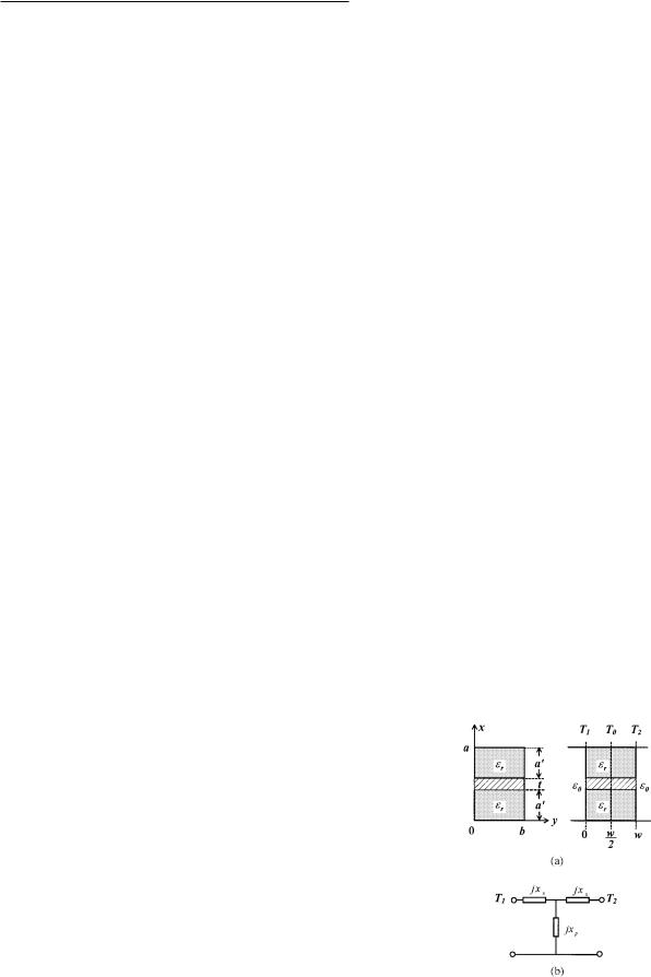
The filter structure is the same as the conventional ones, except that the first and last metal insert regions are filled with a low-loss dielectric material. These regions are the new regions, one of which is shown in Figure 1Ža.. It is analogous to the conventional E-plane metal insert.
Figure 1 Ža. Partially dielectric-filled waveguide bifurcation structure. Žb. Equivalent-circuit model for the metal insert
MICROWAVE AND OPTICAL TECHNOLOGY LETTERS / Vol. 31, No. 3, November 5 2001 |
175 |
