

диафрагмированные волноводные фильтры / 2a639327-181c-42d1-b792-690320392262
.pdf212 |
IEEE TRANSACTIONS ON MICROWAVE THEORY AND TECHNIQUES, VOL. 45, NO. 2, FEBRUARY 1997 |
Optimized E-Plane Bandpass Filters with Improved Stopband Performance
Djuradj Budimir, Member, IEEE
AbstractÐ A computer-aided synthesis technique for E-plane bandpass filters with improved stopband performance is developed. An optimization procedure based on equal ripple optimization is adopted. The design of a symmetrical E-plane bandpass filter with improved stopband performance is considered; higher order mode interaction between E-plane discontinuities is included in the design. The predicted filter performance shows improved stopband performance and reduced filter dimensions compared with conventional E-plane bandpass filters. The validity of the method is confirmed by the measurement of a fabricated five resonator E-plane bandpass filter with improved stopband performance.
I. INTRODUCTION
ALL-METAL inserts placed in the E-plane of a rectangular waveguide along the waveguide axis offer the potential of realizing low cost, mass producible, and low-dissipation-
loss millimeter-wave filters [1]±[3]. However, despite their favorable characteristics, the attenuation in the second stopband (i.e., where the resonators are about one wavelength long) may often be too low and too narrow for many applications, such as for diplexers, when frequency selectivity and high stopband attenuation are considered to be important filtering properties. This is due to the following effect which is characteristic for the common single insert design: beyond the cutoff frequency of the fundamental mode within the septum section, which is determined by the distance between the septa and the waveguide sidewalls, the power is increasingly transported directly by propagating waves [7], causing degradation of the selective properties of resonators based on two septa and the waveguide between them.
In recent years, much effort has been devoted to the study of E-plane bandpass filters with improved stopband performance. Several different solutions have been proposed.
within the waveguide single-mode bandwidth [7]. The reduction of the waveguide housing width decreases the distance between the metal insert and the waveguide sidewalls so that the propagation of modes along the coupling subsections is suppressed up to higher frequencies resulting in an improved stopband attenuation when the passband is not the high end of the waveguide band. Increasing the waveguide housing width reduces the guide wavelength of the filter resonators resulting in an improved stopband performance when the passband is close to the cutoff frequency of the standard width guide.
3)Use resonators of different cutoff frequency [9], [10]. This is achieved by employing sections of rectangular waveguide in which all the waveguide sections are resonant at the same fundamental frequency. However, due to different guide wavelengths in the different sections, the sections are not all simultaneously resonant at any higher frequency, resulting in an improved stopband attenuation.
Therefore, in this paper a new solution for improvement in the second stopband is investigated.
The proposed filter configuration is presented in Section II. In Section III, the circuit representation and design procedure for the design of E-plane bandpass filters with improved stopband performance are presented. The efficient computer implementation of equal ripple optimization is discussed in Section IV, while in Section V design examples are considered to confirm the improvement, and experimental results are presented to confirm the accuracy of the design procedure.
II. PROPOSED FILTER CONFIGURATION
1)Reduce the distance between the metal insert and the waveguide sidewalls by a thick metal insert [4] or use several metal inserts rather than a single one [4]±[6]. The first solution achieves good stopband performance, as is indicated in [4], but has the disadvantage of high passband insertion loss. The second solution also achieves good stopband performance, but requires greater effort in the mounting and adjustment of the several metal inserts in the waveguide.
2)Use narrower or wider waveguide for the filter section depending on the position of the filter passband
Manuscript received December 1, 1995; revised October 18, 1996.
The author is with the Department of Electronic and Electrical Engineering, King's College, University of London, WC2R 2LS, London, U.K.
Publisher Item Identifier S 0018-9480(97)00825-9.
Based on the existing idea to use an increased width waveguide [7], improved stopband performance may be met by the E-plane filter configuration shown in Fig. 1. This is due to the nonlinear relation between guide-wavelength and frequency which may be favorably influenced by a suitable reduction of the cutoff frequency of the fundamental mode within the filter resonators. The proposed filter configuration is constructed of direct coupled ridged waveguide sections which, in general, have identical cutoff frequencies and characteristic impedances, and reactive elements (metal septa) arranged in such a manner that each section is resonant at the same fundamental frequency. The main features of the new structure are the use of conventional rectangular waveguide housing and the use of a metal insert which, when mounted, introduces ridges in the
0018±9480/97$10.00 ã 1997 IEEE

BUDIMIR: OPTIMIZED E-PLANE BANDPASS FILTERS |
213 |
Fig. 1. Configuration of the proposed E-plane filter structures.
Fig. 2. Impedance inverter.
resonators. The improvement in the upper stopband associated with the superior electrical performance of ridged waveguide, such as cutoff frequency reduction, provides a convenient way to realize E-plane bandpass filters with improved stopband performance. The structure is simple and compatible with the E-plane manufacturing process.
III.CIRCUIT REPRESENTATION AND DESIGN PROCEDURE
A. Circuit Representation
The proposed filter structure in Fig. 1 can be represented by using the asymmetrical impedance inverter in Fig. 2 (as shown in Fig. 3). The design of these filters is usually based on the design procedure described in the next subsection, with
the septa being related to impedance inverters. Fig. 2 shows
a two-port |
defined |
by its |
matrix. We |
assume |
that |
|
it is connected to lines of characteristic impedances |
and |
|||||
at its two-ports. It is always possible to find reference |
||||||
planes |
and |
at electrical distances |
and |
from the |
||
respective ports to convert the asymmetric two-port (metal septum in rectangular waveguide between two different ridged waveguides) to the symmetric impedance inverter  . The equations giving the reference plane locations are given in
terms of the |
matrix parameters, leading to the results |
which follow. |
|
The normalized element value of the impedance inverter (Fig. 2) can be derived directly from the normalized 


 matrix of the septum. Normalization is with respect to the guide impedance of the rectangular waveguide. It is given by
(1)
with
(2)
where  ,
,  ,
,  , and
, and  are normalized elements of the matrix given as
(3)
(4)
and  and
and  are normalized guide impedances of the ridge waveguide resonator sections which are frequency dependent.

214 |
IEEE TRANSACTIONS ON MICROWAVE THEORY AND TECHNIQUES, VOL. 45, NO. 2, FEBRUARY 1997 |
Fig. 3. Distributed half-wave prototype using impedance inverters.
The reference plane locations are given by the equations
(5) |
2) Determine the passband ripple level |
from the minimum |
|
|
passband return loss which is defined as
(6)
In practice, electrical distances (
 and
and 
 ) may be realized as negative values in the adjacent positive line length, which therefore becomes shortened in the final network. Mathematical details of the derivations (

 and
and 
 ) are given in the Appendix. Although an impedance inverter has the form of a normalized


 matrix, in the case of an E-plane septum,
  as defined by (1) is not constant and has a nonlinear frequency dependence.
B. Design Procedure
A common approach to the design of the conventional E- plane bandpass filters described in [13]±[15] can be used with minor modifications, for filter structures with different impedances and cutoff frequencies such as E-plane bandpass filters with improved stopband performance. Here, only the most important steps in this design procedure, which should include the concept of impedance inverters and impedances scaling of the impedance levels of the prototype filter will be presented. The design procedure for the E-plane bandpass filters with improved stopband performance is to apply (1), (5), and (6) at the center frequency of the specified passband to calculate the
and which correspond to the impedance inverters. This |
|
approximate treatment |
of the frequency dependence of (1), |
(5), and (6) can result |
in a designed passband which differs |
considerably from that which is specified, and optimization is |
|
|
then required to tune the filter dimensions in order to satisfy |
|
|
the design specification. |
|
|
For a given filter specification such as the two passband edge |
|
|
frequencies yielding |
and , passband return loss |
, |
stopband attenuation |
, the waveguide housing dimensions |
|


 , the metal septum thickness

 , and the ridged waveguide gap

 , the modified design procedure is summarized.
1) Determine the modified scaling parameter  and midband wavelength
  from the following nonlinear equations, which can be readily solved numerically
(7)
(8)
3) Determine the number of resonators  from
from
(9)
at the designated stopband frequency  .
.
4)Calculate the impedances of the distributed element and impedance inverter values from
(10)
and
(11)
where
(12)
5) Recognizing that the normalized impedances of the resonators of the ridged waveguide filters (  ,
, 


 ) are not identical to 1 we must scale the interal impedance levels of the distributed half-wave prototype filter (Fig. 4) as shown in Fig. 5 where
(13)
and
|
(14) |
with |
|
|
(15) |
and |
are the impedance values of the dis- |
tributed half-wave prototype filter (Fig. 4) given by (10)
BUDIMIR: OPTIMIZED E-PLANE BANDPASS FILTERS |
215 |
Fig. 4. Final network of the distributed half-wave prototype using impedance inverters after impedance scaling.
Fig. 5. Equivalent circuit of E-plane filter with improved stopband performance using ABCD matrix for metal septum.
|
and (11), and |
's are the normalized guide impedances |
TABLE I |
||||||
|
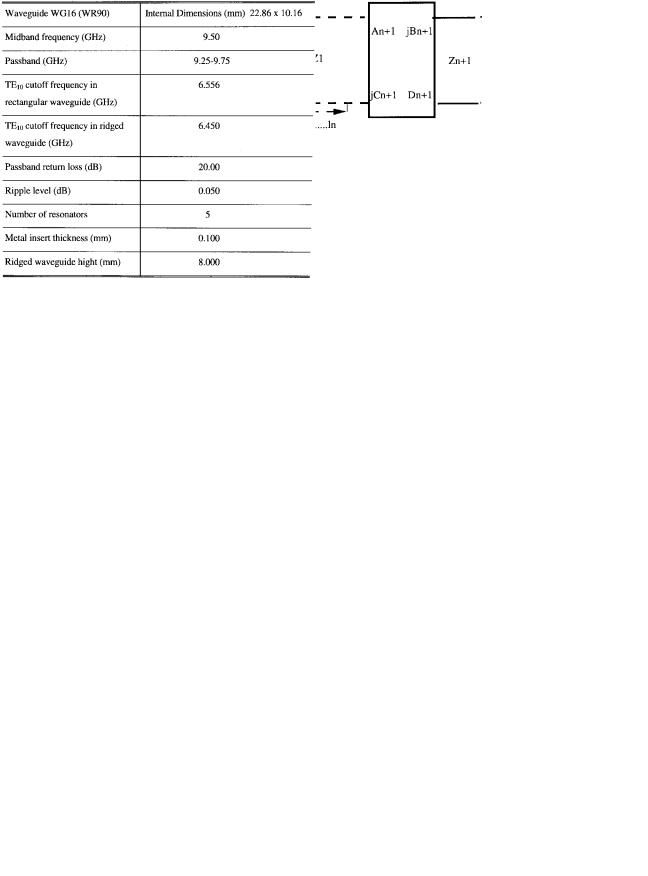
X-BAND FIVE RESONATOR E-PLANE BANDPASS FILTER SPECIFICATION |
||||||||
|
of the resonator sections. |
|
|
|
|||||
|
|
|
|
|
|||||
6) |
Determine the th septum length |
(Fig. 1) by solving |
|
||||||
|
(1) so that the required impedance inverter is realized. |
|
|||||||
|
Since these functions are not available explicitly, we |
|
|||||||
|
must implement a root-seeking routine to find the value |
|
|||||||
|
of width that is provided by the required normalized |
|
|||||||
|
impedance value |
for each impedance inverter. |
|
||||||
7) |
Finally, |
the |
length |
of |
the |
th resonator (Fig. 1) |
|
||
|
formed by the th and |
th septa is given by |
|
||||||
|
|
|
|
|
|
|
|
(16) |
|
|
|
|
|
|
|
|
|
|
|
|
where |
and |
are given by (5) and (6), and the |
|
|||||
|
electrical distance |
corresponds to the physical distance |
|
||||||
|
. |
|
|
|
|
|
|
|
|
The main limitations of this approach are the frequency |
|
||||||||
dependence of the guide impedances and the frequency de- |
|
||||||||
pendence of the impedance inverters or the inaccurate ap- |
|
||||||||
proximation of the E-plane septa made in the derivation of |
|
||||||||
the design procedure. Once the dimensions of the filter have |
plane bandpass filter with the specifications given in Section V |
||||||||
been found, the frequency response of the overall filter at each |
(Table I) is considered. Fig. 7 shows the calculated passband |
||||||||
frequency can be simulated by cascading the |
matrices |
return loss (before optimization±solid line) designed using this |
|||||||
of the resonators and the septa. To illustrate the application |
procedure. As can be seen, the design specification is still |
||||||||
of this procedure to the design of E-plane bandpass filters |
unsatisfactory, and optimization is often required in practice |
||||||||
with |
improved stopband |
performance, |
the design |
of an E- |
for the accurate design of these filters. |
||||
216 |
IEEE TRANSACTIONS ON MICROWAVE THEORY AND TECHNIQUES, VOL. 45, NO. 2, FEBRUARY 1997 |
Fig. 6. Calculated return loss before (solid line) and after (dashed line) optimization (ridged waveguide gap (rwg. gap) = 8 mm).
IV. NUMERICAL IMPLEMENTATION
OF EQUAL RIPPLE OPTIMIZATION
To apply the equal ripple optimization technique [1] to the design of E-plane filters with improved stopband performance, it is necessary, for a given set of insert dimensions, to be able to calculate the insertion loss on a sample of frequency points within the specified passband. For a symmetrical E- plane bandpass filter with improved stopband performance, the insertion loss can be expressed in terms of an 


 matrix. The matrix representation of the whole filter (Fig. 5) is
(17)
with
(18)
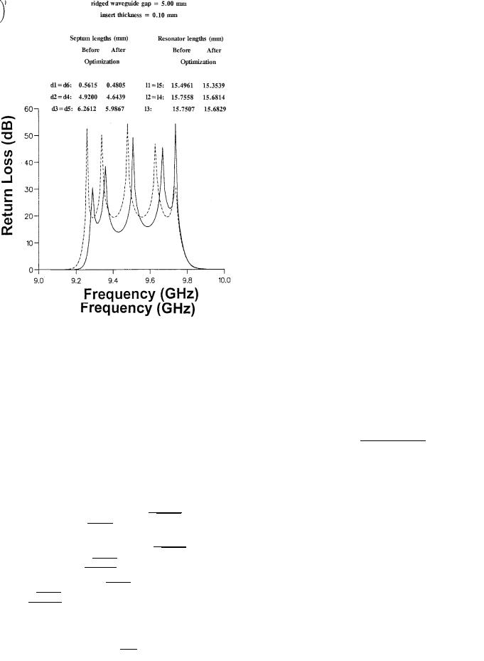
Fig. 7. Calculated return loss before (solid line) and after (dashed line) optimization (ridged waveguide gap (rwg. gap) = 5 mm).
in which 
 is the ridged waveguide resonator length,
 is the wavelength in the ridged waveguide resonator for each frequency, and
  is the cutoff frequency in the ridged waveguide resonator. The overall filter response ([insertion loss (
 ]) can be expressed in terms of elements of the total


 matrix of the filter at each frequency (by directly combining the


 matrices of the individual filter sections) as
(19)
The elements of the 


 matrices of the individual filter sections are calculated using the mode matching method [20], [21]. The propagation constants of the eigenmodes in ridged waveguides are related to the cutoff frequencies, which can be calculated according in [22]. The transcendental equation of the eigenvalue of the
  th mode in ridged waveguide was solved numerically. However, due to the singular behavior of the magnetic field at the edges of the septa, a large number of modes need to be included in the field expansions to ensure good convergence. This points is illustrated by Table I, which shows the slow convergence of the reflection coefficient magnitude of a metal septum with a length of 0.6996

 and thickness of 0.004 3745
  placed between two difference ridged waveguides with gaps of 9.00 mm and 1.00 mm, respectively, as the number of the modes used in the field expansions is increased. Therefore, in order to ensure good accuracy, more than 140 modes need to be included in the field expansions. This is similar to the situation for the septum

BUDIMIR: OPTIMIZED E-PLANE BANDPASS FILTERS |
217 |
Fig. 8. Comparison of calculated insertion loss of X-band five resonator E-plane bandpass filters. Solid lineÐconventional E-plane bandpass filter; d ashed lineÐE-plane filter with improved stopband performance (rwg. gap = 8 mm).
in rectangular waveguide and is due to the singular behavior of the magnetic field at the edges of the septum.
Neither accurate, numerically fitted, closed form expressions nor accurate design tables for the electrical parameters of the E-plane septa in terms of septum dimensions (length and thickness) and frequency are yet available. The accurate design of E-plane filters with improved stopband performance thus requires the direct calculation of the electrical parameters of E-plane septa. This highlights the need in the optimized design of these filters for optimization techniques which minimize the number of calculations of the electrical parameters of E- plane septa. A good approximate design of an E-plane filter with improved stopband performance can be obtained by the procedure described in Section III. This procedure tries to implicitly include the actual frequency dependence of the E- plane septa and results in passbands which nearly meet design specifications. It is therefore adopted in this paper as a means of generating a starting point for the optimization.
V. NUMERICAL AND EXPERIMENTAL RESULTS
In order to demonstrate the advantages of the new E-plane bandbass over the conventional E-plane bandpass filter, a five resonator X-band conventional E-plane bandpass filter and E- plane ridged waveguide bandpass filter (in which the widths
of the ridges are arbitrarily chosen) have been designed. The specifications for these filters are given in Table I. Figs. 6 and 7 show the calculated passband return loss of the E-plane
filters with improved stopband performance (rwg. gap |
mm |
|
and rwg. gap |
mm, respectively) using the approximate |
|
method described in Section III. Mode matching method with 100 modes is used in both the design and calculations; the dimensions of the E-plane insert are given in Figs. 6 and 7. This approximate design was used as a starting point for equal ripple optimization. The passband return loss calculated using the insert dimensions obtained on convergence are shown in the same figures. This took four iterations. Mode matching with 100 modes was used throughout the optimization. Fig. 8 shows the comparison between calculated insertion loss of the conventional and E-plane bandpass filter with improved stopband performance (wg. gap 
 mm). Fig. 9 shows the comparison between calculated insertion loss of the conventional and E-plane bandpass filter with improved stopband performance (rwg. gap
 mm).
mm).
To illustrate the accuracy of the developed method for the design of E-plane filters with improved stopband performance, a ridged waveguide bandpass filter in WG16 was designed. Fig. 10 shows the calculated insertion loss of the final design of a five resonator ridged waveguide bandpass filter (with rwp.

218 |
IEEE TRANSACTIONS ON MICROWAVE THEORY AND TECHNIQUES, VOL. 45, NO. 2, FEBRUARY 1997 |
Fig. 9. Comparison of calculated insertion loss of X-band five resonator E-plane bandpass filters. Solid lineÐconventional E-plane bandpass filter; d ashed lineÐE-plane filter with improved stopband performance (rwg. gap) = 5 mm).
gap 
 mm) over both the
  (8.2±12.4 GHz) and
 (12.4±8 GHz) bands. Also included in this figure is a plot of the measured insertion loss of the fabricated design. The designed filter was fabricated using a brass waveguide housing and a copper metal insert which was realized using spark erosion. Very good agreement between theory and experiment was observed. The measurement over both
  and
and 
 bands was made using an HP 8510C vector network analyzer in two steps.
1)The first was the measurement of the frequency responses of the fabricated filter between 8.2 and 12.4 GHz. A full two-port calibration with short, offset short, sliding load and through as waveguide standards was used.
2)The second was the measurement of the fabricated filter frequency response between 12 and 18 GHz. Since the cutoff frequency of the 

 mode is about 13.20 GHz, this mode becomes a propagating mode for frequencies above 13.20 GHz. By using stepped WG18/WG16 transitions, the generation of the

 mode can be avoided. This is attributable to the fact that as a result of the symmetry of the transition, the

 , like all even modes, is actually not generated in the resonator
waveguides. A full two-port through reflect line (TRL) calibration was used [23]. The only standards required for this are a reflect (short), 20 mm through line and 25 mm line.
VI. CONCLUSIONS
A computer-aided design technique for the accurate design of E-plane bandpass filters with improved stopband performance has been developed. An equal ripple approach to optimization was adopted. The predicted filter performance showed improved stopband performance and reduced filter dimensions compared with conventional E-plane bandpass filters. The analysis of E-plane bandpass filters with improved stopband performance presented in this paper has involved higher order mode coupling between E-plane septa. In order to illustrate the accuracy of the design procedure, five-resonator E-plane bandpass filter with improved stopband performance was fabricated. Measured responses show good agreement with theory.
Fig. 11 shows the photograph of a five-resonator E-plane bandpass filter with improved stopband performance together with the corresponding waveguide housing at  -band.

BUDIMIR: OPTIMIZED E-PLANE BANDPASS FILTERS |
219 |
Fig. 10. Measured (dashed line) and calculated (solid line) insertion loss of X-band five-resonator E-plane bandpass filter with improved stopband performance (rwg. gap) = 8 mm.
(A3)
Defining
(A4)
and dividing (A2) and (A3) by 


 gives
gives
(A5)
(A6)
Solving (A5) for 
 and substituting in (A6) gives
(A7)
or
(A8)
Using the identity
(A9)
then (A8) can be rearranged to give
(A10)
Fig. 11. Photograph of the E-plane bandpass filter with improved stopband performance.
APPENDIX
DERIVATIONS OF THE IMPEDANCE INVERTER EQUATIONS
(A1)
The 


 matrix of the two-port network between two reference planes which, by definition, is an impedance inverter if


 , i.e., if
(A2)
Using the normalization given in (3) and (4), (A10) is then recognized as beng equivalent to (5). Equation (6) is derived by interchanging  and
and  and subscripts 1 and 2 in (A10). Equation (1) is derived by noting that the insertion loss of the impedance inverter is given by
(A11)
which may be solved to give  as a function of
 , resulting in (1).
ACKNOWLEDGMENT
The author would like to acknowledge Dr. V. Postoyalko, Dr. J. Richardson, and Dr. S. Iezekiel, Department of Electronic and Electrical Engineering, University of Leeds, U.K., for useful technical discussions. Thanks are also due to Prof. J. D. Rhodes of Filtronic Components and the Department of Electronic and Electrical Engineering, University of Leeds, who provided expert advice throughout the course of this work.

220 |
IEEE TRANSACTIONS ON MICROWAVE THEORY AND TECHNIQUES, VOL. 45, NO. 2, FEBRUARY 1997 |
REFERENCES
[1]V. Postoyalko and D. Budimir, ªDesign of waveguide E-plane filters with all-metal inserts by equal-ripple optimization,º IEEE Trans. Microwave Theory Tech., vol. 42, pp. 217±222, Feb. 1994.
[2]F. Arndt, ªThe status of rigorous design of millimeter wave low insertion
loss fin-line and metallic E-plane filters,º J. Inst. Electro. Telecommun. Eng., vol. 34, no. 2, pp. 107±119, 1988.
[3]V. P. Gololobov and M. Yu. Omel'yanenko, ªBandpass filters based on planar metal-dielectric structures in the E-plane of a rectangular waveguide (A Review),º Radio-Electron. vol. 30, No. 1, pp. 1±15, 1987.
[4]F. Arndt, J. Bornemann, R. Vahldieck, and D. Granerholz, ªE-plane integrated circuit filters with improved stopband attenuation,º IEEE Trans. Microwave Theory Tech., vol. MTT-32, pp. 1391±1394, Oct. 1984.
[5]V. P. Gololobov and M. Yu. Omel'yanenko, ªFilters based on multilayered metallic structures in a waveguide,º Sov. J. Commun. Technol. Electron., vol. 33, pt. 8, pp. 69±74, 1988.
[6]F. Arndt, D. Heckmann, H. Semmerow, J. Bornemann, and R. Vahldieck, ªStopband optimized E-plane filters with multiple metal inserts of variable number per coupling elements,º Proc. Inst. Elect. Eng., vol. 133, pt. H, pp. 169±174, June 1986.
[7]R. Vahldieck and W. J. R. Hoefer, ªFinline and metal insert filters with improved passband separation and increased stopband attenuation,º
IEEE Trans. Microwave Theory Tech., vol. MTT-33, pp. 1333±1339, Dec. 1985.
[8]J. Bornemann and F. Arndt, ªWaveguide E-plane triple-insert filter,º in
15th European Microwave Conf. Dig., Paris, 1985, pp. 726±731.
[9]H. J. Riblet, ªWavelet filters having nonidentical sections resonant at same fundamental frequency and different harmonic frequencies,º U.S. Patent 3153208, 1964.
[10]J. Bornemann and F. Arndt, ªMetallic E-plane filter with cavities of different cutoff frequency,º Electron. Lett., vol. 22, pp. 524±525, May 1986.
[11]R. Levy, ªTheory of direct coupled cavity filters,º IEEE Trans. Microwave Theory Tech., vol. MTT-15, pp. 340±348, June 1967.
[12]J. D. Rhodes, ªMicrowave circuit realizations,º in Microwave Solid State Devices and Applications, D. V. Morgan and M. J. Howes, Eds. England: Peregrinus, 1980, pp. 49±57.
[13]Y. C. Shih, ªDesign of waveguide E-plane filters with all metal inserts,º
IEEE Trans. Microwave Theory Tech., vol. MTT-32, pp. 695±704, July 1984.
[14]L. Q. Bui, D. Ball, and T. Itoh, ªBroad-band millimeter-wave E-plane bandpass filters,º IEEE Trans. Microwave Theory Tech., vol. MTT-32, pp. 1655±1658, Dec. 1984.
[15]J. B. Lim, C. W. Lee, and T. Itoh, ªAn accurate CAD algorithm for E-plane type bandpass filters using a new passband correction method combined with the synthesis procedures,º in IEEE MTT-S, Dig., June 1990, pp. 1179±1182.
[16]R. Levy, ªThe generalized design technique for practical distributed reciprocal ladder networks,º IEEE Trans. Microwave Theory Tech., vol. MTT-21, pp. 519±526, Aug. 1973.
[17]G. Matthaei, L. Young, E. M. T. Jones, Microwave Filters, Impedance Matching Networks and Coupling Structures. Norwood, MA: Artech House, 1980, ch. 4, 5, 8, 9, 11.
[18]K. C. Gupta, R. Gary, and R. Chadha, Computer-Aided Design of Microwave Circuits. Norwood, MA: Artech House, 1981, p. 530.
[19]J. D. Rhodes, Theory of Electronic Filters. New York: Wiley, 1976.
[20]Y. C. Shih, ªThe mode-matching method,º in Numerical Techniques for
Microwave and Millimeter-Wave Passive Structures, T. Itoh, Ed., New York: Wiley, 1989, pp. 592±621.
[21]A. Wexler, ªSolution of waveguide discontnuities by modal analysis,º
IEEE Trans. Microwave Theory Tech., vol. MTT-15, pp. 508±517, 1967.
[22]J. P. Montgomery, ªOn complete eigenvalue solution of ridged waveguide,º IEEE Trans. Microwave Theory Tech., vol. MTT-19, pp. 547±555, June 1971.
[23]Hewlett-Packard Product Note 8510-8, ªApplying the HP8510B TRL calibration for non-coaxial measurements,º Aug. 1987.
Djuradj Budimir (S'89±M'92) was born in the Republic of Serb Krajina, formerly Yugoslavia. He received the Dipl. Ing. and M.Sc. degrees, both in electronic engineering, from the University of Belgrade, Belgrade, Serbia, and the Ph.D. degree in electronic engineering from the University of Leeds, Leeds, U.K.
In March 1994, he joined the Department of Electronic and Electrical Engineering at King's College, University of London, London, U.K., as PostDoctoral Research Associate. He is a member of the
Department's Communications Research Group. His present research interests include analysis and design of MMIC circuits, the application of numerical methods to the electromagnetic field analysis of passive microwave and millimeter wave circuits, and the design of waveguide filters for microwave and millimeter wave circuits.