

С3.3 (1)
.docCABLE INSTALLATIONS
One of the first steps of the decision process for a new transmission line project is to decide that an Overhead Line (OHL) will not be possible. Following this, the question needs to be clarified if an extruded cable or a Gas Insulated Line (GIL) will offer the best technical and economical solution. This is the question that this technical brochure will concentrate on.
The capacity of a single circuit could be higher when using GIL than in case of a single cable circuit. The application of long cables and GIL may affect the network layout. Also the parallel connection of OHL/insulated cables/GIL will influence the network solution. General statements on handling such questions are included in this brochure.
It is natural to choose an underground solution only when OHL is not possible. Besides AC solutions there are also DC solutions using LCC or VSC technology and in some cases superconducting cables, which are out of scope of this technical brochure.
High temperature super conductive cables (HTSC) are an emerging technology and have had their first installations in city centres with high electric power concentration e.g. Chicago, New York in USA or Essen in Germany. This technology has not been investigated here because only pilot projects have been executed.
A brief history of the evolution of transmission power cables is presented in Table 1.
Table 1 Chronicle of the power cables evolution
Year |
Rated (Phase to Phase) Voltage kV |
Type of cable |
1890 |
10 |
First AC mass impregnated cable - Ferranti |
1913 |
33 |
Mass impregnated cable |
1924 |
132 |
SCFF cable |
1936 |
220 |
SCFF cable |
1947 |
20 |
Extruded Thermoplastic Polyethylene - PE cable |
1952 |
400 |
SCFF cable |
1960 |
20 |
Extruded Cross Linked Polyethylene - XLPE Cable |
1962 |
72.5 |
First extruded LDPE Cable |
1966 |
138 |
Extruded Cross Linked Polyethylene - XLPE Cable |
1969 |
225 |
First extruded LDPE Cable |
1974 |
500 |
SCFF cable |
1979 |
275 |
Extruded Cross Linked Polyethylene - XLPE Cable |
1980 |
1 100 |
SCFF cable (test link) |
1986 |
420 |
Extruded Cross Linked Polyethylene - XLPE Cable |
1988 |
550 |
Extruded Cross Linked Polyethylene - XLPE Cable |
1993 |
800 |
PPL cable (test link) |
2004 |
420 |
First XLPE cable with 2 500 mm2 |
2006 |
420 |
First EHV cable system lead free |
During the 1990's the adoption of extruded EHV cables up to 550 kV voltages found application in some very important circuits of many developed countries. These major circuits are well described in the technical literature [11], in particular, Cigre TB 338 [12] which provides historical statistics on underground cables in power transmission systems and shows that the percentage of underground transmission is strongly variable among countries, and that is decreasing at the higher voltages.
The most common and simple installation of underground cable systems is direct burial along the existing public roads. When the selection of this kind of route is possible then the procedures to obtain the authorization for the construction of new underground lines becomes simplified because only one counterpart has to be taken into consideration. This avoids the requirement to enter into negotiations with a high number of private owners.
The standard installation location of cables is trenches placed aside of the roads in order to minimize the impact on the traffic. After the cable installation, the trenches are refilled with selected soil having good thermal properties for a better evacuation of the heat produced by the losses of the cables when subjected to the full load. In Figure 1 it is possible to see a typical drawing of the trench for the installation of one AC 400 kV cable system for the transmission of the power in the order of 1 000-1 500 MVA.
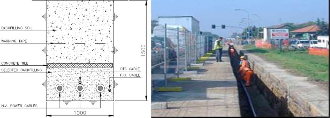
Figure 1: Scheme of the trench for the installation of HV cables and laying works
The picture represents also the live works for the installation of the cables in the trench as indicated in the drawing. As it is possible to see, the trench is excavated along the edge of the road and barriers are placed for protection against the heavy traffic. In most cases, more than one circuit of cables will be installed for the transmission of the the requested load. In presence of limited length and obstacles along the selected route (e.g. road crossings), the configuration of the cables may be changed and other installation techniques may be adopted in order to overcome the obstacle. The document Cigre TB 194 gives the guidance for the construction, laying and installation techniques for extruded and self-contained fluid-filled cable systems. Where the direct burial installation in trenches is not feasible for various reasons such as a very crowded underground by other existing services, it is possible to install cables in dedicated tunnels of shared infrastructures. Figure 2 shows the installation of EHV cables in tunnel.
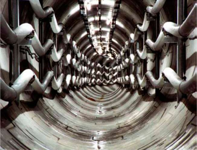
Figure 2: HV cables installed in a tunnel bored about 20 m under ground level in Berlin
The service experience of HV extruded insulation cables dates back more than 40 years for 245 kV and more than 30 years for 420 kV, with excellent performances. This technology can now be considered as consolidated, well supported by commercial available materials and components and guaranteed by efficient standards with stringent requirements, demonstrated performances in service, and available diagnostics methods. A survey on the transmission underground and submarine cable systems reliability is available from Cigre. The reliability characteristics of the individual equipment items play a decisive role in the security of the electrical supply. Nowadays there are specific and stringent IEC standards and Cigre recommendations that are applicable to the design and requirements of the transmission cable systems in order to assure a high quality and reliability of the components for the designed or expected life time.
The current carrying capacity (ampacity) of insulated cables must be computed according to IEC 60287 series of standards.
The current rating of the cable system is depending on the cable laying conditions; typically the maximum power that can be transmitted for a cable system is in the range of 1 000-1 500 MVA per circuit (three single core cables) that is working at voltages in the range of 420-550 kV. By adopting forced cooling a maximum power in the range of 1 500-2 000 MVA per circuit can be transmitted.
GIL or cable installations are designed for specific current ratings. These ratings are based on network requirements and are given for a specific ambient temperature. The GIL or cables are consequently designed to meet the requirements of their corresponding standards for the maximum allowed temperature rises.
During normal operation, the load current going through the GIL or cables circuits should not exceed these rated continuous currents. In such cases, we talk about steady state conditions. However, in some circumstances, the circuit can be operated at higher current values. This can occur when the ambient temperature is lower than 40 °C (design value). This can also be required when a circuit is out of order and the load needs to be transported through the remaining circuits. In such case, we talk about temporary overload. In both cases, it is possible to go beyond the rated values without jeopardizing the integrity of the equipment.
The maximum continuous current is determined by the manufacturer, considering various factors such as ambient temperature, installation conditions, heat radiation, convection, etc. Whatever the rating assigned, the maximum temperature rises determined in respective GIL and cable standards shall be respected (refer to the previous chapter on rating of equipment).
The capability of the equipment to transport high current is linked to its capability of evacuating the joules losses. These losses are proportional to the resistance of the equipment multiplied by the current factor n. This coefficient n is dependent on the characteristics of the equipment and is generally between 1.6 and 2. The capability to evacuate joules losses is also dependent on the ambient temperature.
As a result, if the temperature is lower than the 40 °C, the GIL or cable equipment can be operated continuously at a current higher than the rated continuous current. If the current is lower than the rated continuous current, the maximum ambient temperature of operation of the equipment can be higher than 40 °C.
For high voltage GIL equipment, the following formula is generally used to evaluate the allowable continuous current (Is) for a given ambient temperature in steady state conditions.
Figure 3 gives an indication of relation between capability of equipment and temperature.
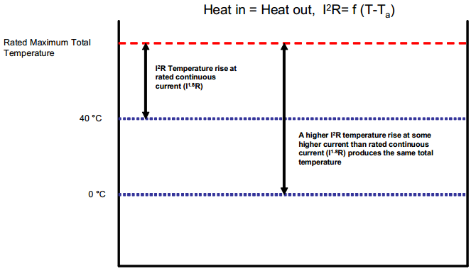
Figure 3: Relation between capability of equipment and temperature
Equipment may also be assigned an overload capability for higher than rated continuous current for a temporary period provided the temperature does not exceed the maximum temperature value specified in corresponding GIL or cable standards. The maximum overload values are dependent of the pre-load conditions and also of the time constant of the equipment. Figure 4 explains the relation between temperature rise of the equipment and the current overload capability.
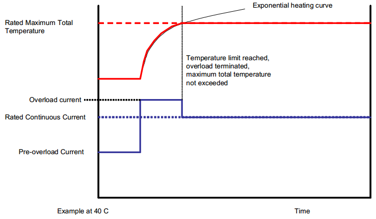
Figure 4: Relation between temperature rise of the equipment and the current overload capability