

книги / Методы и технологии добычи нефти и газа
..pdffractures are, partially or completely, closed, and, instead of flow rate increase according to formula (16), it can be decreased because efficient permeability becomes much lower in formula (2).
Minimal values of bottomhole pressure under which well flow rate is not becoming lower if underbalance Pr–Pbh is increased should be determined experimentally when well testing. It is not recommended to reduce bottomhole pressure lower than such minimal values.
3.Usually, oil contacts water-saturated part of reservoir in the bottom or in flanks. Water viscosity is, as a rule, lower than reservoir oil viscosity. Under high underbalance (high values of ∆Рr), water can flow to bottomhole from the bottom or breakthrough from flanks along the most permeable layers (stringers) of rocks. Together with water, oil inflows to well. In all cases, water content in oil well flow causes various problems: corrosion, formation of high-viscosity emulsions in wells and on surface (in the gathering system). On surface, it is necessary to remove water from oil and inject it both for its disposal and for maintaining reservoir pressure. If well is shutdown, water is accumulated in the bottom part of well, i.e. bottomhole, as water density is higher than oil density (water is heavier than oil), and penetrates the part of reservoir along which oil flows to bottomhole. When well is brought into operation, oil flows in porous rock medium (in bottomhole formation zone) which contains penetrated water. According to the fundamentals of Petroleum Reservoir Physics, oil filtration in the presence of water (another phase) in porous rock medium is worse. So, oil influx becomes lower. Thus, bottomhole pressure must be sufficient to prevent water breakthrough.
4.Reservoir oil always contains asphaltens, resins and solid paraffin. Resins and paraffin are dissolved in oil, and asphaltens can be partially in dissolved state and partially in the form of dispersed fine particles. When oil flows from bottomhole to wellhead, oil pressure and temperature becomes lower. At the given temperature, which is termed paraffin crystallization point or paraffin saturation point, paraffin
20
recovers from the dissolved state and crystallizes. Resins can recover from oildissolved state at higher temperatures, and it is promoted by oil-dissolved gas transfer to free phase. The lower well pressure relative to bubble point pressure, the less dissolved gas is in oil (fig. 6). Dissolved resin and paraffin retaining power of oil becomes lower. If bottomhole pressure is equal to bubble point pressure Рbp or lower, the transition of oil-dissolved substances to another state can start in the bottomhole, and rate of such transition becomes higher as oil lifts to the surface. As a result, the so termed asphaltene-resin-paraffin deposits are formed on the surfaces of tubing string and other well equipment. Asphaltene-resin-paraffin deposits can partially or completely cover tubing flow area, thus, creating serious problems in well operation. Asphaltene-resin-paraffin deposits are formed deeper as bottomhole pressure Pbh decreases, all other conditions being equal.
21
Ivan R. Yushkov
PETROLEUM RESERVOIR ENGINEERING
ANALISIS AND CONTROL
1. INTRODUCTION
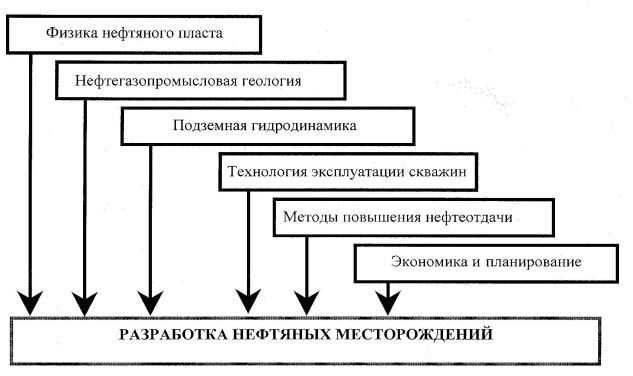
Petroleum reservoir engineering is characterized by integrated use of various principles of geology, geophysics, petrophysics, subsurface hydrodynamics, rock mechanics, petroleum production engineering and petroleum production, economics and planning systems.
Petroleum Reservoir Physics
Petroleum Field Geology
Subsurface Hydrodynamics
Petroleum Production
Engineering
Enhanced
Oil Recovery
Economics and Planning
Petroleum Reservoir Engineering
At the same time, petroleum reservoir engineering is not a conglomerate of geology, subsurface hydromechanics, petroleum production engineering and economics, but a self-standing integrated field of science and engineering discipline with special sections related to reservoir engineering systems, processes and technologies, planning and implementation of engineering philosophy, design and control.
22
Petroleum reservoir engineering system can be termed as a totality of engineering solutions which characterize a development target as geological and technical system. Such totality includes the drilling-out sequence and reservoir (pool) development rate; formation stimulation for oil and gas recovery; number, ratio and pattern of injection and production wells; number of standby wells, reservoir engineering management, conservation of mineral resources and environment. To develop the reservoir engineering system means to work out the above totality of engineering solutions.
Development target is a geological body (stratum, solid mass, structure and series of strata) artificially delineated within the field to be developed, which contains the commercial hydrocarbon reserves to be extracted by pattern of wells or other mining facilities.
Reservoir engineers, to use the terminology of oilmen, generally believe that each target should be developed by “its own well pattern”. It should be noted that nature itself does not create any development targets – they are delineated by reservoir engineers. Development target can include one, several or all reservoirs.
The key features of development target are commercial reserves and pattern of wells peculiar to the given development target.
2. RESERVOIR ENERGY SOURCES
Energy is a physical magnitude that describes the ability of bodies to do work. In terms of oil and gas production, work is a difference of energies or released energy required for oil and gas migration and lift to the surface. There are natural reservoir energy and artificial energy, if it is transmitted from outside (from the surface).
All oil or gas reservoirs are characterized by potential energy which is converted to kinetic energy and provides oil or gas displacement during development.
23
Reservoir energy is accumulated in oil or gas reservoir, during the reservoir formation, under action of water drive system of the given reservoir. Moreover, other sources of reservoir energy (elastic forces of oil, water and rock; gas compressed in gas caps; and oil-dissolved gas) are formed and accumulated under action of this system during reservoir formation. In addition, oil gravity force acts in reservoirs.
Reservoir energy resources are estimated from reservoir pressure change while oil or gas extracting from it. As a rule, the higher initial reservoir pressure, the higher reservoir energy resources. Natural reservoir energy margin and quantity can be determined both by the initial reservoir pressure value, and by the total volume of the entire system formed the given productive reservoir, including its oil (gas) zone and surrounding water zone. The most complete picture of reservoir pressure can be obtained by reservoir pressure change nature and rate during development.
Before reservoir is drilled-in, reservoir fluid and gas are in static state and distributed vertically according to densities. When reservoir is drilled-in and well operation started, the balance is disturbed: fluid and gas begin flowing to low pressure zones, i.e. bottomholes.
Fluid and gas flow in reservoir due to reservoir pressure and bottomhole pressure difference. In other words, the accumulated reservoir energy is used for fluid and gas flow in reservoir and lift to the surface, i.e. to overcome resistance when flowing.
Depending on geological conditions of oil or gas reservoir and development conditions, reservoir energy can manifest itself in the form of combination of forces driving reservoir fluid and gas flow.
In major part of oil reservoirs, oil flows under action of forces created by edge water drive.
In oil reservoirs with large gas cap, flow is caused by forces created by compressed gas pressure and expansion.
24
In gas reservoirs, gas flows under action of forces created by gas expansion simultaneously with reservoir pressure decrease.
In case of poor interconnection of oil reservoir pore space with water-saturated part of reservoir, oil mainly flows under action of forces created by oil-dissolved gas bleeding and expansion.
If water drive system of oil reservoir is large, reservoir energy is expressed in the form of elastic expansion of fluid and rock under reservoir pressure decrease, even if such system is not interconnected with the surface.
In a number of reservoirs, especially at the late stage of development, the main driving forces in reservoir are gravity forces: oil flows from the higher parts of reservoir to the lower parts at which bottomholes are located.
In course of fluid filtration through porous rock medium, resistance forces are created, and part of reservoir energy is used for overcoming such forces.
Oil or gas reservoir drive depends on reservoir energy type and pattern in the process of development.
It is accepted to term a drive by driving force dominating in reservoir for the time being.
3. OIL RESERVOIR DRIVES
Depending on the kind of energy of oil and gas drive, there are the following oil reservoir drives:
1)water drive;
2)gas cap drive;
3)dissolved gas drive; and
4)gravity drive.
In addition, there are also elastic drive and elastic-water drive, considering influence of elastic fluid and gas expansion on reservoir.
25
Oil reservoirs are often characterized by combination of driving energies. Draining conditions of such reservoirs are termed combination drive.
Reservoir drive is dictated by both artificially created development conditions and by natural conditions. This or that reservoir drive can be established, maintained controlled and even replaced with another. To a great extent it depends on rate of fluid and gas withdrawal and other development processes (working agent injection and other). Reservoir drive is established based on the geological conditions and energetic characteristics of the reservoir, but it does not completely depend on them.
Water Drive
Under water drive, oil flows in reservoir under action of encroaching water, and, ideally, the reservoir is constantly made up with water from the surface sources. Therefore, the condition of water drive existence is a contact between productive reservoir and ground surface. Contact zones of the productive reservoir and surface can be hundreds of kilometers distant from the oil part of reservoir.
Water drive can be also created artificially by water injection in special injection wells located within the water zone of reservoir outside the oil pool outline. In pure water drive, encroaching water completely displaces oil and gas withdrawn. Oil drainage boundary is continuously reducing and shifting to the center of the reservoir.
Under water drive operation, reservoir pressure, first, is slightly decayed and, this causes pressure gradient establishing under which water flows into pay zone. In time, in the course of continuous fluid withdrawal, reservoir pressure is stabilized, and such stabilization indicates that water drive with complete withdrawn oil displacement has been established.
In case if rate of oil withdrawal increases, there can come a point when capacity of the water drive system becomes insufficient under the given water drive, and water volume, which manages to flow into petroleum reservoir, becomes less than volume of extracted fluid. Reservoir pressure begins lowering and this can cause water drive transfer to dissolved gas drive.
26
Because of slow reservoir pressure decrease in water drive reservoirs, well flow rate is approximately constant for a long time, as well as gas-oil ratio.
Before development, oil-water contact in water drive reservoir is in horizontal position, and, under development, it moves to the center of the reservoir.
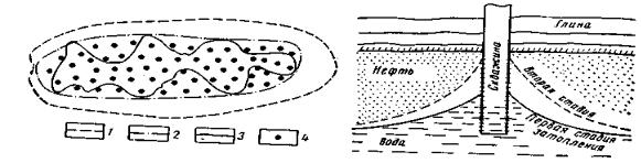
With oil drainage, oil-water contact gradually rises, and oil drainage boundaries shrink to the center of the reservoir. Wells located close to the oil drainage boundary are drowned first, and, later on, wells located close to the center of the reservoir. Reservoir development ceases when encroaching edge water reaches bottomholes in the upper parts of reservoir, and, instead of oil, only water is produced. However, even though all wells of the reservoir are completely drowned, the reservoir still contains substantial quantity of unrecovered oil. Such process is compounded by the fact that composition and permeability of oil-containing rocks, in the majority of cases, is heterogeneous, and, therefore, reservoir fluid (oil and water) flow rate is higher in layers with higher permeability. As a result, the encroachment line can move to the center of the reservoir unevenly, and this causes lateral coning (fig. 1). And if there is bottom water, high rate of oil withdrawal promotes water breakthrough from bottom. As a result, more and more water ingresses together with oil and water cones are formed (fig. 2). Finally, wells can produce only water despite the fact that there is still large amount of oil in reservoir.
Fig. 1. Lateral Coning Formation: |
Fig. 2. Water Cone Formation |
1 – outer oil pool outline; 2 – inner oil pool |
|
outline; 3 – encroachment lines; 4 – wells |
|
Depending on water drive features in oil reservoirs, the most favorable conditions for water drive are: 1) high intercommunication between oil and water part of res-
27
ervoir; 2) high permeability and homogeneity of reservoir structure; 3) low oil viscosity; and 4) compliance of rate of recovery from reservoir with water encroachment rate.
The most uniform movement of oil-water contact to all directions with maximum effect of water-oil displacement can be reached under the above conditions.
Elastic-Water Drive
Reservoir fluids and rocks are compressible, so, under reservoir conditions, they store elastic energy that releases under reservoir pressure decrease.
Elastic change of rock and fluid volume under reservoir pressure decrease, in terms of unit of their volume, is not significant. But considering the sizes of reservoir and its water drive system, the elastic energy of rocks, fluids and gases can be a significant factor of oil influx.
Reservoir fluid and rock expansion under pressure decrease can take place under any reservoir drive, but, it is of secondary importance under water drive or gas drive. Under bottomhole pressure decrease, fluid, which is located closely to the bottomhole, will expand due to elastic force, but pore volume, which accumulates fluid, will be compressed, and the part of fluid will be displaced from reservoir.
The higher reservoir volume affected by pressure decrease, the larger mass of fluid is carried by flow to bottomhole.
The basic feature of elastic-water drive is significant reservoir pressure drop at the initial period of operation, and, as elastic expansion zone is extended, reservoir pressure decrease rate slows down.
If constant reservoir pressure is maintained, well flow rates decrease, especially in the beginning. Then, well flow rate curve becomes flatter. Gas-oil factor is constant, as it is under water drive, until reservoir pressure becomes less than bubble point pressure.
Elastic properties of reservoir and saturating fluids manifest themselves in the fact that any reservoir pressure change in any point of reservoir is propagated along the reservoir not instantaneously, but at some rate. Such propagation of reservoir pres-
28
sure within the reservoir is dictated by piezoconductivity which depends on physical properties of fluid and reservoir, and it is characterized by piezoconductivity factor:
χ = k /µ ( т βf+ βpm) = k /µ β*
where χ is piezoconductivity factor, m2/sec; k is reservoir permeability factor, m2; µ is absolute or dynamic viscosity of fluid, Pa*sec; т is porosity, fractions of unit; βf is fluid compressibility factor, 1/Pa; βpm is porous rock medium compressibility factor, 1/Pa; and β* is elastic capacity factor, 1/Pa.
Piezoconductivity factor can be determined, best of all, by processing well interference test data related to various reservoir trends.
Gas Cap Drive
Under gas cap drive, oil is displaced by pressure of expanding gas which is in free state in the upper part of reservoir. This process is similar to water-oil displacement. The only difference is that water displaces oil in the upper part of reservoir, and gas displaces oil in the lower part of reservoir.
Volume of gas under pressure in gas cap is always less than volume of water-drive system surrounding oil reservoir, and that is why compressed gas energy is always limited.
Gas viscosity is very small in comparison with oil viscosity. In the process of oil displacement and gas expansion in gas cap, gas can breakthrough to wells located near gas-oil contact. Gas breakthrough promotes waste of gas energy under simultaneous oil influx reduction. Therefore, under gas cap drive, it is necessary to control closely operation of wells located near gas cap, run on choke, and, in case of sudden increase of gas amount in oil flow on surface, stop well operation. Such measures make it possible to economize reservoir energy and achieve the highest oil recovery. To enhance oil reservoir performance under gas drive, it is necessary to inject gas to the upper part of the reservoir. This makes it possible to maintain and, sometimes, to restore gas energy in reservoir.
29